Connecting pedals to a Sega Dreamcast Race Controller
Friday, 30th September 2022
I recently built some Dreamcast Race Controller "De-Dead Zone" mods for people and before popping them in the post I tested them in my wheel. During this process I noticed an unpopulated region of the main PCB:
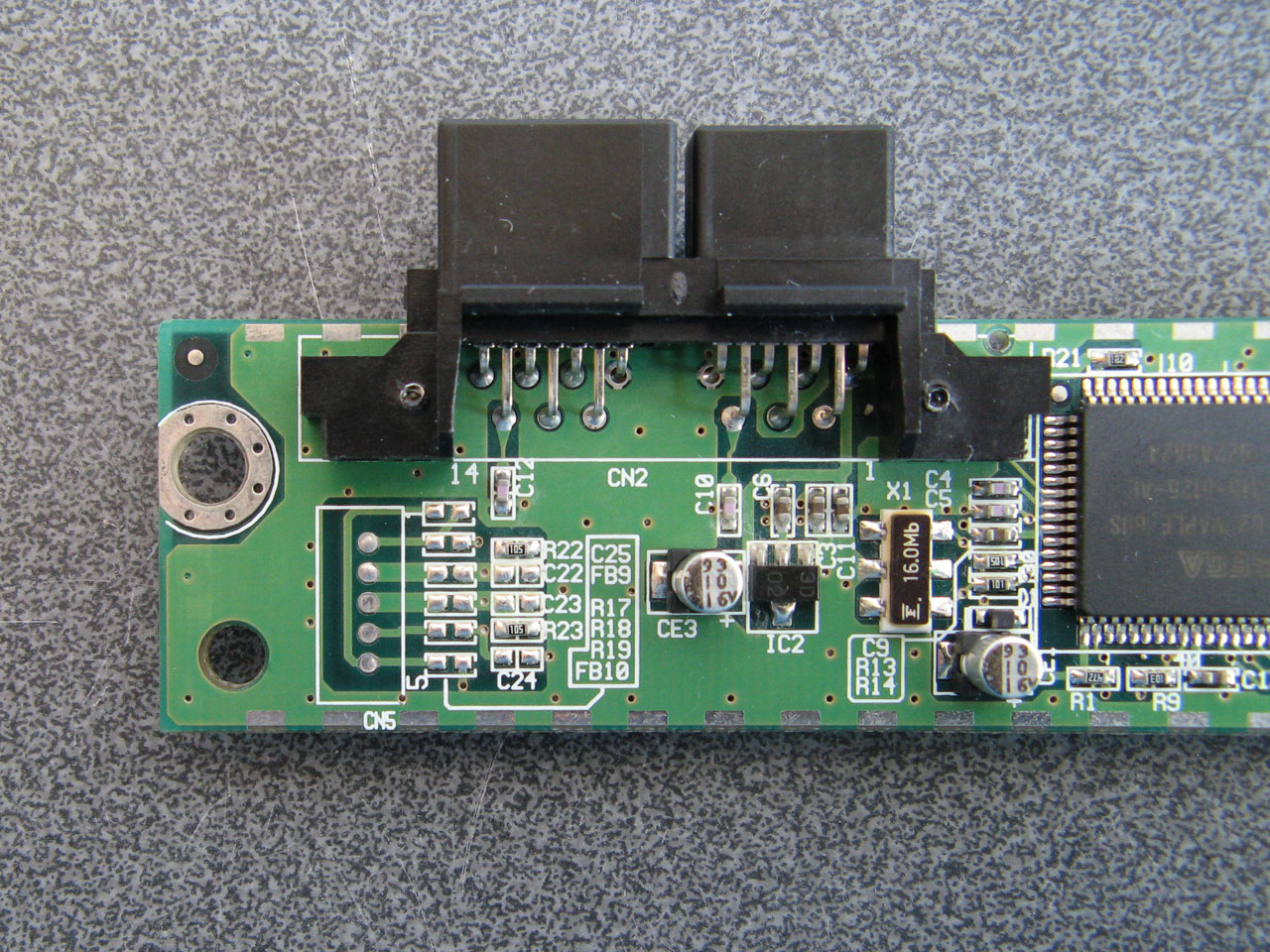
I remember reading that some versions of the Race Controller had a socket on the back for the connection of a set of pedals, however those pedals were never released and games instead rely on a pair of analogue paddles mounted behind the wheel for braking and acceleration. I wondered if the pedal functionality was still available on my wheel, even though it lacks the relevant socket on the back. I traced the connections of the unpopulated components and made a guess of their values, based on their name (e.g. FB9 is presumably a fuse, C22 is presumably a capacitor) and comparing their function to other similar sections of the circuit. This is the circuit I arrived at:
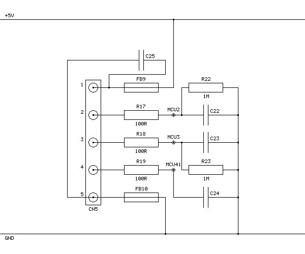
FB9 and FB10 connect +5V and GND to CN5's pins 1 and 5 respectively and are presumably the power connections for the pedals. R22 and R23 are 1MΩ pull-down resistors that were already present, and based on the thick traces from CN5's pins 2 and 3 and connection to two adjacent pins on the main microcontroller these are part of the analogue inputs from the two pedals. CN5's pin 4 is eventually connected to another pin on the microcontroller with a 10KΩ pull-up resistor, and my assumption is that the pedals should connect this pin to ground so the wheel can detect whether they are plugged in or not.
Other parts of the wheel use 100Ω resistors in series with their analogue inputs so I followed their lead. I'm not sure of the capacitor values; I picked 100nF for the C25 capacitor across the power supply lines and 10nF for the capacitors to ground on the other inputs (C22, C23 and C24) but these are complete guesses as I don't own a capacitor meter to test the similar components on other parts of the board.
As I also don't have the small surface-mount parts in stock I connected wire links across FB9, R17, R18, R19 and FB10 and then soldered five wires to CN5 so that I could build a small circuit on a breadboard with the resistors and capacitors on it. I then connected this to my racing wheel pedals:
| CN5 Pin | Function |
|---|---|
| 1 | +5V |
| 2 | Pedal 1 analogue voltage |
| 3 | Pedal 2 analogue voltage |
| 4 | Pedal detect (connect to GND) |
| 5 | GND |
With the pedals connected like this the race controller does detect them and sends their status back to the Dreamcast console, however no game software I have tried has been able to work properly with the pedals. Games either ignore the pedals entirely or complain about an unsupported or disconnected controller. However, if you run the 240p Test Suite's controller tester you can see the pedals reported as two additional axes that operate independently of the existing analogue paddles.
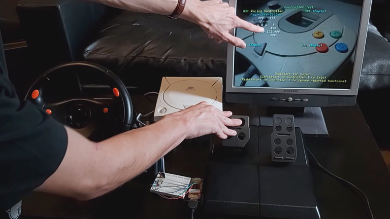
The video above shows a demonstration of how the wheel and pedals perform in a handful of games and the 240p Test Suite, with that test suite being the only software I've found that can show the status of the pedals. It's a bit disappointing that no games seem to support the wheel and pedals together, but I thought it was interesting to see that the functionality is at least present in the wheel hardware.