2MHz should be enough for anyone
Wednesday, 27th August 2008
 LCD Timing
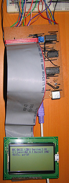
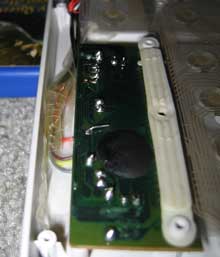
Last time I discussed the hardware I mentioned I had LCD timing issues. I have finally resolved them, but this has been the most time consuming part of the project so far.
The first thing to sort out was the LCD's E pin. Once you have set up the LCD's input pins to a state where they're ready to read or write data, you need to drive this pin high. I had had some success by holding it high permanently and relying on the Z80 to set all the other to the right state at roughly the same moment, but this was inaccurate and resulted in occasional display glitching.
Consulting the datasheet, it appears that once the input pins are ready E needs to be held low for at least 450nS and then needs to be driven high for at least 450nS. Hmm. During an I/O request (and once the Z80 has prepared the address and data bus) there's a delay of 1 clock cycle, then /IORQ is held low for about 2.5 CPU cycles. That is the window of opportunity. I have connected a binary counter to the Z80's clock signal and take the least significant bit of the output - every clock cycle this output toggles between a low and a low, effectively halving the CPU clock rate. I then connect the counter's reset pin (which overrides the clock input and forces it to output zero) to /IORQ. The result is that when the Z80 is not accessing hardware the counter is held in its reset state, and E is held low. When the Z80 holds /IORQ low, the counter starts up and outputs a zero for one CPU cycle, outputs a one for the next CPU cycle, then outputs a zero for the next half clock cycle at which point /IORQ goes high again and it is back to zero anyway. This is exactly what's needed!
This also allows us to calculate the maximum CPU clock rate. If we are generous and allow E to be low for 500nS then high for 500nS, that gives us a CPU clock rate of 1/500nS=2MHz.
Anyhow, that's one problem resolved, but there was still one nasty bug. When reading from the LCD it would occasionally end up writing to the area that was being read or, in worse cases, the Z80 would "crash". The LCD has a R/#W pin that is held high when reading and held low when writing. I had connected it directly to the Z80's /WR pin, which is high normally and low when writing. The problem here is "normally" as the LCD was expecting to be read even when the Z80 wasn't requesting a /RD. When being read, the LCD expects to put something onto the data bus, and it appeared that it kept thinking that it needed to put something on the bus when it wasn't needed. This caused fighting with the other chips that were trying to put their own values on the data bus, hence the crashes as the Z80 received invalid data.
The answer was very easy; simply connect the Z80's /RD pin to the LCD's R/#W pin via a NOT gate. In the default state the pin is held low (LCD expects a write and leaves the data bus alone), and only goes high during a /RD. The LCD interface is now very robust.
CPU Clock
Above I mention the calculation for the maximum clock rate. Rather than use the 555 for timing, I switched to using a 10MHz crystal resonator oscillator. I'm using the serial resonant circuit from z80.info with a 74F04 hex inverter (second circuit down). Fortunately the counter chips I have are decade counters (ie, designed to count from 0 to 9) made up of a ÷2 and a ÷5 section. I can connect a 10MHz oscillator to the ÷5 section and use the output of that to drive the CPU. In the final design I'd like to add a "hardware control port" with a bit that would let the programmer choose 2MHz or 10MHz mode by setting or resetting a particular output bit (other control bits would include switching the LCD backlight on or off and a buzzer for beeping sound output).
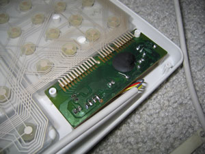
PS/2 Ports
As a friend pointed out, the 8-bit open-collector I/O port (which will drive two PS/2 ports, the I2C bus and TI calculator link port) had a flaw - there was no resistor on the base of the output transistors. The result is that if the output latch tries to drive the transistor base high, the transistor switches on and shorts the output of the latch to ground. This was clearly a problem in the design as the LCD backlight dimmed when trying to output to these ports as they drew a excessive amount of current when effectively short-circuited. A 22K resistor between the output latch and base of the transistor fixed the problem.
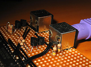
In the above photo, I've also added two 100K resistors to hold the output high when floating, but only to the foreground PS/2 port for the time being. I don't think I'll be controlling a mouse yet!
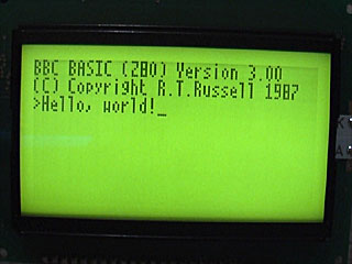
Revised OS
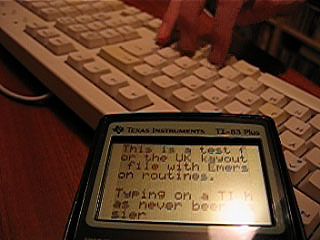
With a little modification of the Emerson PS/2 library I've got a basic keyboard driver up and running on the hardware. All the OS does for the moment is check for keys and display them on the screen. It's currently hard-coded to the UK layout, as I haven't yet decided how I'm going to handle storage and by keeping the layout in ROM it at least frees up a few hundred bytes of RAM that would otherwise need to be there for the scancode translation tables.
Internal PS/2 Port
Friday, 6th October 2006
What's that in the bottom left hand corner?
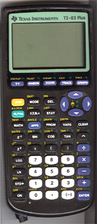
Kerm Martian has added a PS/2 port to his calculator (click the picture for better pictures and the original thread). He has been developing a shell, entitled DoorsCS (click for website) which sports an impressive set of GUI controls - hence the mouse!
Emerson Beta 2
Friday, 22nd September 2006
Sorry about the lack of updates, but I have been incredibly busy with work related programming.
One small project I've had a chance to update is Emerson - my keyboard and mouse library for the TI-83 series calculator.
I know, I can't type layout.  Download the library (and demo) here.
TI-83 Plus Mouse
Tuesday, 21st February 2006
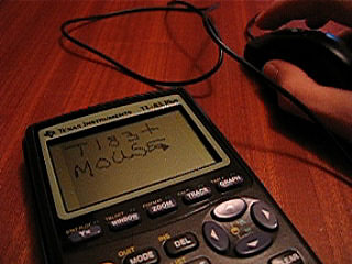
I had another go with my AT protocol routines to see if I could persuade a PS/2 mouse to do anything.
It would appear that I could...
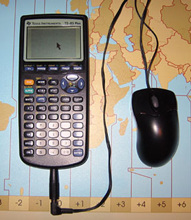
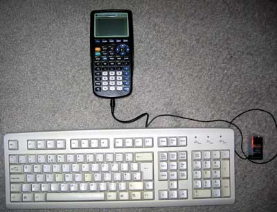
There are two cables for the mouse as there were for the keyboard - one goes to the TI, the other goes to the power supply. The mouse is put into the lowest resolution mode (the cursor is moved 1 pixel per mm).
There's a demo for anyone with a TI-83 Plus and an adapter. It also contains a keyboard demo - and there's a video of that demo here (1MB WMV).
Fortunately, I didn't have to butcher that mouse (it's a rather good miniature USB/PS2 one), but it is connected to the TI with Blu-Tak to keep the wires on the contacts, and isn't very mobile as I only gave the power lead about 15cms clearance. I think it's high time I grabbed myself some proper connectors and a soldering iron from Maplin...
As for the mouse routines - they need a lot of tidying up and making much more reliable, especially in the recovery when a mouse is disconnected then reconnected (my keyboard routines are 'hot pluggable', after all). Extending them to support the Microsoft Intellimouse system, giving the mouse an extra axis (scroll wheel) and two extra buttons would be rather cool as well.
Ultimately, these routines are rather useless until they become widely adopted. Ideally, they could/would be added to a shell, and form part of the standard routines. For example, the shell could provide a "get key" function, which would also transparently return keyboard keys as if they were keys on the keypad, or return four "left" keys if the mouse was moved 4 mm left -- that sort of thing.
Chances of this happening are, sadly, nil.
Localisation
Thursday, 17th November 2005
Typing
One reason you'd want to connect a keyboard to your TI - or indeed any device - would be to type on it. After all, it offers a nice comfortable layout to type quickly on...
One easy way to deal with the keyboard as a typing device would be to write a function that converts the scancode into an ASCII code (or a special code in the 128→255 range for keys without sensible ASCII equivalents, such as the Windows or cursor keys). But here's the problem - not all keyboards have the same characters printed on the keys. A UK layout will be QWERTY, a French layout will be AZERTY and a German layout will be QWERTZ. A US keyboard will have @ over the 2, whereas my keyboard has " over the 2.
The way I get decided to get around this was a fairly inelegant (but simple) one - assume the calculator has a keyboard localisation file on it. A function call I have provided called keyi_load_table will attempt to find and load the keyboard layout definition file you can create (returning an error code if it can't find any). Any software that uses these routines can therefore instantly tailor themselves to match the keyboard layout of the individual user. The files themselves aren't very big - it contains two mappings for the entire keyboard (normal and shifted), a table of which keys Caps Lock affects (26 bytes - A→Z on an English keyboard) and a final table for alternate codes for when Num Lock is pressed.
With this all put together, a single call to keyi_translate will convert a scancode in the accumulator to the ASCII/special code, automatically adjusting for Shift/Caps Lock/Num Lock. You can even call the function keyi_check_printable to see if the code is in the printable character range, or keyi_get_status_icon to get a character code for a suitable cursor - no special status returns , shift returns ↑, caps lock returns A and caps lock+shift returns a.
Getting it to work
Wednesday, 16th November 2005
Reliability
I'm sure you wouldn't want to use a keyboard that was inaccurate. Unfortunately, (as you might have seen me moaning in the past) the keyboard generates the clock signal. This basically means you need to be constantly checking the clock line to see if it goes low - that or use a hardware interrupt the jumps in and receives the scancode packet when the keyboard decides you want to stop sending something.
Well, I don't have the luxury of an extra keyboard chip or a hardware interrupt, so I needed to don my thinking cap. I had thought that one possible way around this would be to send a "disable" command to the keyboard after receiving bytes, running my handler code, then sending an "enable" command - these commands clear the keyboard's buffer, unfortunately, which is not good.
I downloaded another document on the AT protocol to see if they mentioned anything useful, and lo and behold:
The host may inhibit communication at any time by pulling the Clock line low for at least 100 microseconds.
I think I can spare 100µs - I added the line ld a,1 \ out (bport),a to the end of my buffer-filling code from earlier (it fills a scancode key buffer) - and the code doesn't drop a single scancode. Result!
Providing useful functionality
All these keyboard routines do at the moment is to display the data coming in on the screen - not exactly a great use of them. What is really needed is a simple two-way handler - it calls two different user-defined routines based on what a key is doing, whether it is being pushed down or released.
For this, I should translate the scancodes into a new format - there are less than 256 keys, so there's no reason why I can't fit every single key into a byte.
As well as user-defined keyboard events, I'll have to add my own to handle toggling the status of the keyboard - the num/caps/scroll lock as well as the shift/alt/ctrl.
It's really quite simple to do.
	; Now we need to run through all the keyboard events!

	ld ix,_buffer	; Start at the beginning of the buffer.

_handle_next_scancode:

	; Let's assume it's a normal key:

	ld hl,_scancode_lut
	ld bc,_scancode_lut_end-_scancode_lut

_key_down_handler:
	ld de,_null_handler


	ld a,(ix+0)
	or a
	jr z,_handled_all_keys

	cp at_scs_enhance	; Is it an enhanced key?
	jr nz,_not_enhanced

		inc ix	; We know it's enhanced, so move along.
		ld a,(ix+0)
		or a
		jr z,_handled_all_keys
		ld hl,_scancode_e_lut
		ld bc,_scancode_e_lut_end-_scancode_e_lut
_not_enhanced:

	; Now HL points to our LUT, BC is the correct length
	; and IX points to the next byte.

	cp at_scs_keyup ; Is it a key UP event?
	jr nz,_not_keyup

		inc ix
		ld a,(ix+0)
		or a
		jr z,_handled_all_keys
_key_up_handler:
		ld de,_null_handler

_not_keyup:

	; Move to next chunk before we do anything
	inc ix
	; At this point, A=scancode, HL->translation table, DE->handler, BC=table size, IX->next scancode.

	; We now need to run the translation.

	cpir	; Simple as that!

	jr nz,_handle_next_scancode	; Not found

	; So HL->scancode+1
	; Here is where the magic happens:

	push de
	ld de,0-_scancode_lut
	add hl,de
	ld a,l
	pop de

	; Now, A = 'real' scancode.

	; We need to 'call' DE.
	; We can spoof this easily:

	ld hl,_handle_next_scancode
	push hl	; _h_n_s is on TOP of the stack.
	push de ; our event handler is on top of the stack;
	ret	; POP back off stack and jump to it.
		; When the handler RETs it'll pop off _h_n_s and carry on scanning!


_handled_all_keys:

_null_handler:
	ret
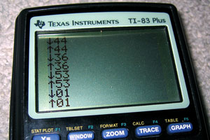
I created a couple of very basic event handlers - the key down event displays ↓ followed by the adjusted key code, the key up event displays ↑ followed by the adjusted key code.
What would be ideal would be to provide internal event handlers that could be called on keyup/keydown which would then jump over to the user's custom handler. These event handlers could look for special keys and adjust the keyboard LEDs and set internal flags that could be used to detect the status of certain keys. I'd need:
- Num Lock
- Caps Lock
- Scroll Lock
- Shift
- Ctrl
- Alt
Unfortunately, I think that there is a problem with my byte-sending code. Setting the keyboard LEDs starts to do strange things - I now have two options;
- After switching status, ignore the LEDs. The status flag is set correctly internally, but you can't see it on the keyboard (which is a bit pants).
- Update the status flags every single time we run through the loop to check for any new bytes (which makes the keyboard lag like crazy - there's up to half a second of buffering going on!)
Mixing-and-matching the two - rewriting the branch before we bring the clock high again (for maximum speed) confuses the keyboard - the status LEDs never change and it decides to disable itself in a strop until I send $FF (the reset command) again. I think it's time to revisit the at_send_byte routine again to see what it's doing wrong!
Well, comparing it to my new notes - it's actually completely wrong at the end, when it comes to sending the parity/stop/ACK bits! A quick rewrite to how I think it should go isn't too hopeful - the keyboard LEDs flash like mad. Tweaking the timing by throwing in a few calls to _wait_bit_low and _wait_bit_high to synchronise my data to the clock stop this completely - and now the code is as it was before, at 100% accuracy - but about twice as fast.
Replacing my branch code still doesn't work all the time - sometimes the LEDs change, sometimes they do not. Not believing it would work, I threw in a check for the ACK bytes returned - if they were $FE, the 'repeat last command' byte, I'd send again.
My routines were clearly not as broken as I thought - the keyboard LEDs now change status perfectly, and as much as I hammer the Num Lock, Caps Lock and Scroll Lock keys, I cannot lock up the program or get the keyboard LEDs to display the wrong value. Not to mention that keying in other keys is back to the lightning fast response they used to be...
TI Keyboard
Tuesday, 15th November 2005
Once again, I waste my time doing something remarkably useless - it's trying to connect a keyboard to my TI graphing calculator!
Idea
Alas, this is not an original idea - I had seen some work done on this in the past, and tried fiddling with the code myself, not really understanding much of it. I decided to have a go - from scratch, and on my own.
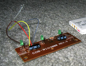
Constructing the hardware
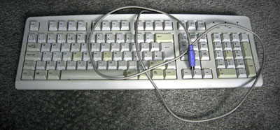
I decided to butcher an old, suitably discoloured keyboard (in a nice way, though, so if all went wrong I could reassemble it). I don't have a soldering iron, nor any sort of decent cabling or plugs so I planned to just cut and strip the wires inside the keyboard and attach (by twisting together and large amounts of Sellotape) a power cable and 2.5mm stereo minijack plug (the TI has a 2.5mm stereo minijack socket on it as a data port).
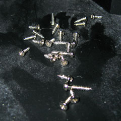
I'm not sure they put enough screws into this thing... (by contrast, my main keyboard has a whopping 2 screws in it - this keyboard's designer was clearly paid by the screw!)
Finally (and with a slightly sore wrist), I get to the bit I need - the keyboard controller board. The circuit board has the four leads soldered straight into it - I'd been hoping for the more typical sight of a block that the cable plugs into, but unfortunately it looks like I'll be cutting wires and hoping not to snap them off by accident. The four wires have been labelled VCDO - I'll cross my fingers and assume these stand for VCC (+5V), Clock, Data and 0V.
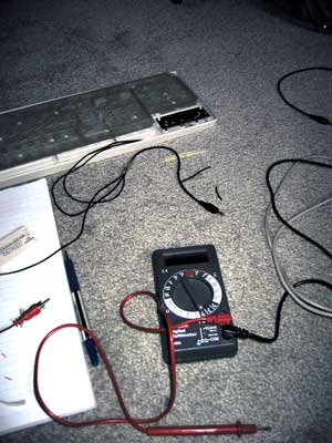
Out it comes, the wires are stripped and reattached. I then tested all the leads using my multimeter and created some stunning ASCII art to remind me what went where:
HARDWARE SCHEMATIC:

PS/2 SOCKET:                               TI CONNECTOR:

  6.-++-.5      4: VCC   >-[+5V]                _
  /o || o\      5: Clock >---< 1: Red    Tip   /_\.
 |   ++   |     1: Data  >---< 2: White  Ring  }_{
4|o      o|3    3: Gnd   >-+-< 3: Copper Base  | |
  \      /               __|__                 |_|
   \o__o/                 ---  0V             /   \.
   2    1                  '                  \___/===> To TI
 ^ Note that this is the SOCKET view
and not the plug view for a PS/2 port.
With that done, I taped down the connections and screwed the whole thing back together. Tapping a 9V PP3 battery to the power leads makes the keyboard boot up; doesn't look like it's broken quite yet!
Writing the code
What with the hardware now hopefully complete, it's a simple case of writing the code to support the keyboard. *cough cough*
Basically, I need to write an implementation of the AT protocol. The protocol is fairly simple, but unfortunately the keyboard generates the clock signal for us (the TI doesn't have accurate timing at all - it's an RC circuit, and so the clock rate drops as the batteries go flat). Let's hope the TI can keep up!
I guess the easiest code to write would be code that sets the output high (as it's an open collector circuit, high is the default level - either side can pull this low and hold it there) then poll the clock and wait for it to drop then go back up again. The clock line maps to bit 0 of the link port, and the data line to bit 1 of the link port. The TI's data IO port can be controlled using these two lower two bits of the hardware port equated as 'bport' (port 0) in ti83plus.inc
Here's what I tried;
init_all:
    ; Set link port high
    ld a,%00000011
    out (bport),a


wait_bit_low:
    in a,(bport)        ; Read in the status of the bport.
    and %00000001       ; Mask out bit 0 (clock)
    jr nz,wait_bit_low  ; Is it non-zero (high?) If so, loop back.

wait_bit_high:
    in a,(bport)        ; Read in the status of the bport.
    and %00000001       ; Mask out bit 0 (clock)
    jr z,wait_bit_high  ; Is it zero (loop?) If so, loop back.

    ret                 ; Break out of the program
Strange, whatever I do - init the keyboard, tap keys, nothing happens. The program goes into an endless loop. Using the 9V to manually set the line low then high again, I realise something - I keep forgetting that the port works backwards, and that writing %00000011 sets the status to %00000000 - and when a line is held low by either device, it can't be brought up again very easily. Replacing the offending line with xor a to clear it to zero worked a treat - pressing any key on the keyboard exits the program.
Each "packet" on the AT protocol (it's a bit grand to call it that) is made up of 11 bits - 1 start bit, 8 data bits and 2 parity/stop bits. A djnz loop to get the 8 bits and a handful of rotate instructions to populate the result byte gives me this:
.module AT_Protocol

at_timeout = 255

at_get_byte:
    ; Clear Link port
    xor a
    out (bport),a

    ; Get the start bit:

    call _wait_bit_low
    call _wait_bit_high


    ; Now we need to get the 8 bits for the byte

    ; Reset the output byte
    ld c,0

    ld b,8

_get_byte_loop:

    call _wait_bit_low

    ; Now we get the bit itself
    in a,(bport)
    rrca
    rrca
    rr c

    call _wait_bit_high

    djnz _get_byte_loop

    ; Get the parity/stop bits

    call _wait_bit_low
    call _wait_bit_high
    call _wait_bit_low
    call _wait_bit_high

    ; Clear flags, load code into accumulator and exit
    xor a
    ld a,c
    ret

_get_byte_fail:
    ; Set nz to indicate failure, return.
    or 1
    ret


_wait_bit_low:
    push bc
    ld b,at_timeout
_wait_bit_low_loop:
    in a,(bport)
    and 1
    jr z,_waited_bit_low
    djnz _wait_bit_low_loop
    pop bc
    pop bc
    jr _get_byte_fail
_waited_bit_low:
    pop bc
    ret

_wait_bit_high:
    push bc
    ld b,at_timeout
_wait_bit_high_loop:
    in a,(bport)
    and 1
    jr nz,_waited_bit_high
    djnz _wait_bit_high_loop
    pop bc
    pop bc
    jr _get_byte_fail
_waited_bit_high:
    pop bc
    ret
Not too tricky at all! Amazingly, this code ran first time too. (Amazingly for me, that is). The test program just reveices a byte from the keyboard and displays it on the screen.
One minor problem is that sometimes the code received differs by a bit to what it should (you can see this by holding down a key and noting how sometimes the code is different - I've written a short program that just displays the code on-screen when it's received). Consulting my AT protocol notes, I find that "After the clock line goes low a 5-microsecond pause is used so that the data line has time to latch." Maybe my pause isn't long enough?
Sadly, that did quite the opposite - the results are even more unpredictable. I guess it would be more better to try speeding up my code, rather than slowing it down..?
After increasing the speed a little (without unrolling all the loops, that is) the routines are (by and large) slightly more accurate. Still not perfect, but they'll do for the time being. If I press a key the release it just before it repeats, the accuracy is 100% perfect - I suspect that the problem is that in the time the rest of my program has drawn the last keycode, the keyboard has pottered away and tried to output another byte and I'm jumping in half way through. I guess I'll have to write some clever buffering code to handle that!
Interrupts
I thought that an ideal way to handle the timing/speed problem was to create a piece of code that could be loaded as a sort of driver. The calculator would be set up into interrupt mode 2 and would call the driver 100-or-so times a second. The code could then try to see if a byte was coming in, and if so it would add it to a buffer. A routine isolated from the rest of the code could then read a byte from the buffer and shift all the other items down to replace it - a sort of FIFO stack.
The Z80 has three interrupt modes; 0, 1 and 2. Interrupt mode 0 is pretty useless to us; interrupt mode 1 is the normal mode of operation. In this mode, the CPU pushes the program counter to the stack then jumps to memory location $38 every time an interrupt occurs. The interrupt handler then swaps the main CPU registers away with their shadow register pairs, does something, then swaps the CPU registers back again. Finally, you pop the old program counter off the stack and jump back to where you were. You could think of it as having a second thread running, only a lot less hi-tech and more restrictive.
Interrupt mode 2 is a stranger beast. The main difference is that it doesn't just jump to $38 - it creates a 16-bit address using the register I as the most significant byte and a byte off the data bus as the least significant byte - effectively, we have a 16-bit number made up of i*256+?. The CPU then loads the value in the memory location pointed to by this 16-bit value, then calls this address.
What does this mean for us? Well, it means that rather relying on the interrupt at $38 we can load our own interrupt into memory!
We need to do three things:
- Create a 257-byte lookup table aligned to a 256-byte boundary for the CPU to read from after it has build up the 16-bit address.
- Set the I register to the most significant byte of the start address of our lookup table.
- Copy our interrupt handler to the location our table points to, switch the interrupt mode to two and enable interrupts.
The way I've done this is:
- Filled memory locations $8700 to $8800 (inclusive) with the byte $86.
- Loaded $87 into the I register.
- Copied my interrupt handler to $8686
My interrupt handler at $8686 is a simple jp instruction to jump back to my program for the sake of practicality.
Unfortunately, this approach doesn't work (and I tried a lot of different ways to get it to!) One reason for failure is that in im 2, the main interrupt handler at $38 isn't getting executed. The TIOS relies pretty heavily on this interrupt to work; most functions cause a pretty nasty crash or do other strange things. Fine, I say to myself, and replace my reti call at the end of my interrupt handler with a jp $38 to manually call the TIOS interrupt. The behaviour gets even stranger - calling ionFastCopy (a function, non-TIOS related, to copy the display buffer to the LCD) causes strange rippling effects to appear on the LCD, followed by a full-out crash when I finally quit the program.
On top of all this, the few times I can get a display of the key buffer I can see that it's not updating very frequently... The interrupt is not checking the port frequently. All this for nothing!
As far as I can see it, the only way for an interrupt-based technique to work would be for the TI to have a hardware interrupt - using the keyboard's clock connected to the CPU, so that whenever the clock goes low the TI could spring into action and receive the byte. Seeing as the only access to the CPU I have without invalidating my warranty is via the data port, I'm a bit stuck.
Back to square one
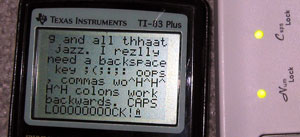
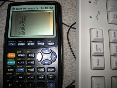
I guess the only way is to agressively poll the port... First up, I rewrote the code so that instead of displaying a decimal version of the code, I'd display a hexadecimal version - significantly easier to read, faster to convert. I then painstakingly noted down every key's scancode from this into a useful include file.
One problem with the original TI keyboard project was that it had problems with input; it would occasionally forget about shift being pressed, or accidentally repeat keys. I think I now know why...
On an AT protocol keyboard, scancodes are sent every time a key is pressed and again when the key is released. To differentiate between the two different actions, when a key is released the scancode is preceded by the special code $F0.
I reckon that the problem was that the function to get a byte would have been called, followed almost immediately with the code to translate/display it. What I intend to do instead is to get bytes in a loop and add them to a buffer until either the routine times out (no more bytes being sent) or the buffer is full (shouldn't happen!)
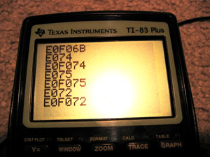
As you can see, this system works. The above codes are special ones generated by pressing some of the extended keys (the cursor keys) - they send the code $E0 followed by the key itself. Some of the codes are downright silly - PrintScreen sends the command string E0F07CE0F012 when released - Pause sends E11477E1F014F077!
Infuriatingly... this is STILL not perfect! I'm still losing some bytes. What to do - if only there was a way to control the keyboard, to stop it from scanning... wait a minute...
Controlling the Keyboard
Sending a byte is not too different from receiving a byte - you hold the clock and data lines low, then just the data low, then write out the bits as the keyboard requests them on clock. The easiest code to transmit is $FF - keyboard reset. According to my notes, the keyboard should respond with the power-on self-test byte as well as resetting. Lo and behold, the keyboard lights flash and I get $AA back - the self test has passed. I also get $E8 back, and my notes don't mention $E8 anywhere, but I'll ignore that for a minute and bask in the glory of it otherwise working perfectly.
The next code I try is $EE. This is the echo code - in theory, the keyboard should send back $EE. Sadly, it doesn't. Damn. It just resets and sends back $AA, though it sometimes sends back $B8 as well.
On close inspection, it seems pretty obvious what I've done wrong - I'm completely neglecting to send the parity and stop bits. Oops. After adding them, the keyboard responds $EE to my $EE - which is quite correct! The parity is hard coded, so I'm glad it works.
Trying another code, $F2, gets the keyboard to spit back an unfriendly $FE - which translates as "resend, you idiot". $EE is %11101110, which contains 6 set bits. $F2 is %11110010 which contains 5 set bits - the parity needs to be reversed. Hopefully calculating the parity shouldn't consume too many clock cycles - after I extract the bit to send, I need to add it to another counter. I can then use the lowest bit of this counter as my parity bit.
Thankfully, I have sufficient time to calculate the parity - the keyboard now responds FAAB83. $FA is the ACK code, AB83 are the ID bytes. Scarily, my notes say that the ID bytes are $83 then $AB - I'm going to hope that this is an error in the notes - I doubt my routines are going to be able to mix up whole bytes!
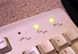
Now for the main reason you'd want to send codes to the keyboard - to flash the LEDs, of course! The code is $ED - the keyboard should respond with an ACK ($FA), to which I send the status byte (the lower 3 bits control the LEDs). The code is pretty simple (albeit without any checking on the ACK):
    ld a,$ED
    call at_send_byte   ; Command
    call at_get_byte    ; ACK
    ld a,%00000101      ; Caps Lock and Scroll Lock on
    call at_send_byte   ; Command
    call at_get_byte    ; ACK
Ace. I'll add the equates for the various commands to my include file. No doubt I can get some more done with this project tomorrow...
Subscribe to an RSS feed that only contains items with the Emerson tag.