dsPIC33 VDC with GLCD or PAL TV output
Sunday, 4th July 2010
I have currently been using some terminal emulation software on my PC to see the output of the Z80 computer. It seems a little silly to rely on a large multi-gigahertz, multi-megabyte machine just to display the output from a machine at the megahertz and kilobyte end of the scale. I had previously done some work with a dsPIC33 to drive a 320×240 pixel graphical LCD so dug out its breadboard and dusted off the code to try to make something of it.
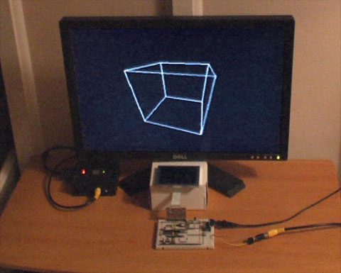
Inspired by John Burton's recent experiments with PAL TV output I decided that the first thing I should do is add support for TV output. The graphical LCD is nice but a little small and responds to pixel changes rather slowly, making animation very blurry.
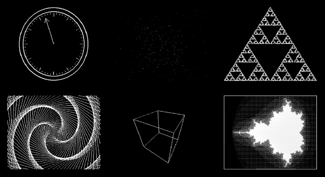
I think the results are reasonably good. A lot of the code is shared with the old LCD driving code, which means that the LCD demos work fine with the TV too. Fortunately, retracing the TV is a much less CPU-intensive job than retracing the LCD. The PIC has an SPI peripheral that allows you to clock out eight or sixteen bits a bit at a time at a selected speed by writing to a single register, which is great for clocking out the pixel data on each scanline. Even better are the PIC's DMA channels, which allow you to output a selected number of bytes or words to a selected peripheral from a specified location in RAM with no CPU involvement; all I need to do on each line is to copy a complete scanline to the DMA memory, initiate a transfer from this memory to the SPI peripheral and the job is as good as done. Using the DMA hardware as opposed to writing to the SPI registers directly reduced the rendering time of the Mandelbrot fractal part of the demo from 33 seconds to 18 seconds.
One problem I haven't been able to resolve is that the PIC inserts a small delay between every DMA/SPI transfer, which results in every sixteenth pixel being a bit wider than the fifteen before it. This is especially noticed on dithered regions. If I write to the SPI registers directly this delay vanishes. I'm not sure if the picture quality increase is worth the loss of performance, so I'd rather find a proper fix for this! For the time being, here's a video of the demo as it currently runs:
The TV contains a 75Ω resistor to ground on its composite video input. Two resistors are used on two PIC pins to form a voltage divider to produce the required output voltages (0V for sync, 0.3V for black and 1V for white). When the TV is disconnected the output of the circuit is 3.3V (the supply voltage, equivalent to a logic "high") as there's no load resistance to pull it to the correct 0.3V (a logic "low"). This can be used to periodically check whether a TV is connected and to switch between the LCD and TV output modes.
The above is rather vague, and I would recommend Rickard Gunée's article entitled How to generate video signals in software using PIC for more detailed information! The code for the demo can be downloaded from my website for those who are interested.
Update: I've updated my code to use the SPI peripheral in slave mode and use a timer and output compare unit to generate the clock signal. This regular clock signal produces pixels of identical sizes the new code can be downloaded here.
Controlling a PG320240H-P9 with a dsPIC33FJ128GP802
Sunday, 21st March 2010
In a previous entry I mentioned that I had purchased a PG320240H-P9 graphical LCD. This is a 320×240 white-on-blue pixel display, and it does not have an on-board controller or RAM. To display something on it you need to constantly refresh it with picture data; in this instance, sending four pixels at a time, starting from the top left and working from left to right, top to bottom — a bit like the scanning pattern of a CRT monitor.
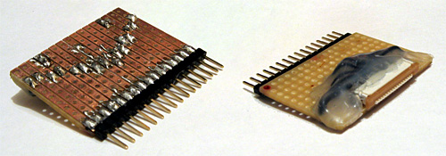
Connecting a circuit to the LCD is made slightly more tricky by its use of a 16-pin 1mm flexible flat cable. To get around this I soldered together an adaptor using a suitable FCC connector, pin strip, piece of stripboard and a fairly excessive quantity of hot melt adhesive. Even more tricky was the lack of a suitable datasheet for the LCD. After some digging I located this one for the PG320240WRM-HNNIS1 — it's slightly different, but contains timing diagrams and specifications that seem to work with the LCD I bought. One thing I still haven't worked out is the contrast adjustment; a 5K variable resistor between 0V and the relevant pin seems to have had the best results thus far. A helpful webpage, Graphical LCD controller for ST8024+ST8016 based displays, has a plain English description of how to drive the LCD, though as far as I'm aware the M pin should have its logic level toggled every frame, giving you a "glass" frequency of half of the refresh rate, not 200Hz-400Hz. The lack of a proper datasheet makes these things a little complicated!
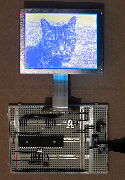
My first attempt to drive the LCD involved an ATmega644P, a microcontroller with 64KB of flash ROM and 4KB of RAM. The above photo shows it displaying a picture of a cat, which was stored in ROM and output using the following code:
#include <stdint.h>
#include <avr/io.h>
#include <avr/pgmspace.h>

#define LCD_FLM   (6)
#define LCD_M     (5)
#define LCD_C1    (4)
#define LCD_C2    (3)
#define LCD_D_OFF (2)

#define LCD_CONTROL_PORT (PORTC)
#define LCD_CONTROL_PIN  (PINC)
#define LCD_CONTROL_DDR  (DDRC)

#define LCD_DATA_PORT    (PORTA)
#define LCD_DATA_PIN     (PINA)
#define LCD_DATA_DDR     (DDRA)

#include "cat.h"

int main(void) {

    // Make control pins outputs.
    LCD_CONTROL_DDR |= _BV(LCD_FLM) | _BV(LCD_M) | _BV(LCD_C1) | _BV(LCD_C2) | _BV(LCD_D_OFF);

    // Make data pins outputs.
    LCD_DATA_DDR |= 0b1111;

    // Enable the LCD.
    LCD_CONTROL_PORT |= _BV(LCD_D_OFF);

    for(;;) {

        // Toggle the M pin to provide the LCD AC voltage.
        LCD_CONTROL_PIN |= _BV(LCD_M);

        const uint8_t* picture_ptr = cat_picture;

        // Scan 240 rows in the image.
        for (uint8_t row = 0; row < 240; ++row) {

            // Begin the line.
            LCD_CONTROL_PIN |= _BV(LCD_C1);
            LCD_CONTROL_PIN |= _BV(LCD_C1);

            if (row < 2) LCD_CONTROL_PIN |= _BV(LCD_FLM);

            // Send 40 eight-bit words.
            for (uint8_t column = 0; column < 40; ++column) {
                LCD_DATA_PORT = pgm_read_byte(picture_ptr) >> 4;
                LCD_CONTROL_PIN |= _BV(LCD_C2);
                LCD_CONTROL_PIN |= _BV(LCD_C2);
                LCD_DATA_PORT = pgm_read_byte(picture_ptr);
                LCD_CONTROL_PIN |= _BV(LCD_C2);
                LCD_CONTROL_PIN |= _BV(LCD_C2);
                ++picture_ptr;
            }
        }
    }

}
A 320×240 display has 76,800 pixels, and if you store each pixel as a single bit (so eight pixels per byte) you need 9600 bytes to store a complete frame, which clearly won't fit in the 4KB offered by the ATmega644P. Rather than upgrade to an AVR with more memory, I jumped to the dsPIC33FJ128GP802, a 16-bit microcontroller with 16KB of RAM. As well as quadrupling the RAM from the ATmega644P it also doubles the program memory (128KB from 64KB) and speed (40 MIPS from 20 MIPS). When working with AVRs I'd been using a slow home-made serial programmer, and rather than continue with this sorry state of affairs (lack of debugging capabilities is never fun, especially when it takes over a minute to program the microcontroller) I treated myself to a PICkit 3 Debug Express.
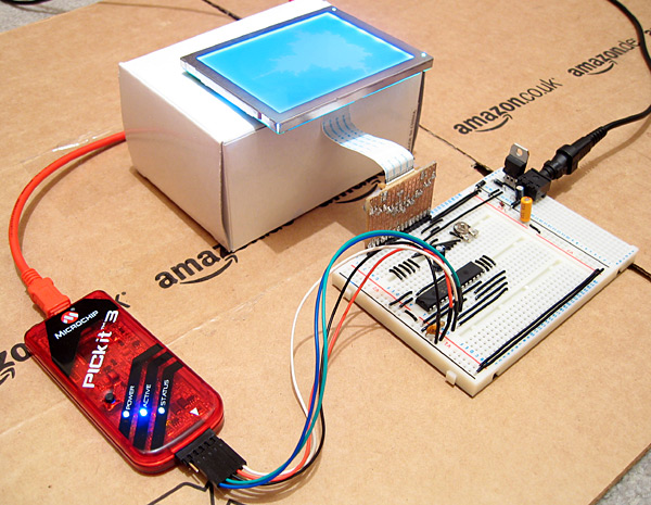
The above photo shows the LCD connected to the microcontroller as well as the PICkit 3. The dsPIC33FJ128GP802 requires a voltage supply from 3.0V to 3.6V, not the 5V I am used to, so to power it I have put two IN4001 rectifier diodes in series with the 5V regulator output. Each diode incurs a voltage drop of 0.7V, producing 3.6V for the rest of the circuit. The LCD is powered from the main 5V supply, but it seems happy with the 3.6V logic "high" from the dsPIC.
The LCD is connected to the dsPIC as follows:
- FLM to RB15
- M to RB14
- C1 to RB13
- C2 to RB12
- /D_OFF to RB11
- D0~D3 to RA0~RA3
A 10K resistor is included between /D_OFF and ground. This is very important, as it holds the /D_OFF line low when RB11 is floating (e.g. during reset), forcing the display off — if the display is powered, but is not being actively refreshed, the LCD panel can become overloaded and damaged.
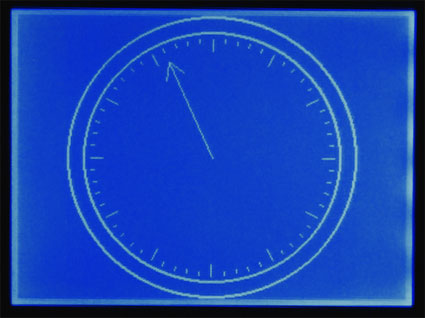
I have knocked together a simple demo that shows a few different graphics on the LCD. The LCD is constantly refreshed by an interrupt service routine that runs in the background, leaving some CPU time to the user program. As there is only enough RAM for a single frame buffer, animation has to be quite simple to avoid flickering, but I've still managed to include my favourite spinning cube.
The project can be downloaded here. I'm still getting to grips with the dsPIC series; the code is likely to be pretty awful, and I still have a problem where the dsPIC resets itself every couple of minutes (I'm not really sure if this is a software or hardware issue). Still, it's a start, and I hope that I can use this LCD as the display for my Z80 computer project.
Update: Having seen this post, the chap who originally suggested that I investigate the dsPIC33FJ128GP802 sent me an email with some advice, chiefly about my poor power supply, missing decoupling capacitors and use of an electrolytic capacitor on the VCAP pin. I have since replaced the two rectifier diode affair with a proper 3.3V regulator for the power supply, added a decoupling capacitor across AVDD/AVSS and moved the decoupling capacitor between VDD/VSS closer to the microcontroller. I have also ordered some tantalum capacitors to replace the electrolytic one. A bit of debugging found that the watchdog timer is responsible for the spurious resets; I have disabled it in the code for the time being, which has stopped the resets.
Subscribe to an RSS feed that only contains items with the PG320240H-P9 tag.