Text and filled shapes for the dsPIC33 VDC
Thursday, 22nd July 2010
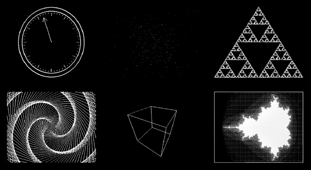
The dsPIC33 video display controller project I am working on needs to support several common text output and drawing operations offered by existing BBC BASIC implementations. The previous demo included basic point, line and circle outlining functions, but I also need to output text and outline (or fill) rectangles, circles, ellipses and triangles. On top of that the drawing operations need to support multiple colours and plotting modes. Owing to processing power and memory limitations the output is black and white only but different "shades" can be implemented with dither patterns. The plotting modes allow you to perform logical operations between what you are drawing and what's currently on the buffer — for example, you could fill a circle that is logically ORed with the existing background or draw a line that inverts every pixel along its length rather than applying the new colour.
Filled rectangles and text output produce the above image.
Finding suitable algorithms for some of these routines has been a little tricky at times. Due to the way that filled shapes can be set to invert (rather than overwrite) what's on the background there has to be zero overdraw and the outline of filled triangles should exactly match the outline of a triangle drawn by plotting a line between its three vertices; this makes combining triangles to form more complex shapes possible, as you can guarantee that the overlap between the two shared vertices of a pair of triangles covers the same pixels as a line drawn between those two vertices.
Filled triangles produce a solid cube.
I ended up writing a program in C# that would plot a random triangle using the triangle filler I was attempting to write and then compare its outline to that of a triangle drawn by plotting lines between the three vertices. The final code is chock full of special cases and workarounds but has been tested against hundreds of thousands of random triangles and seems to be working!
Due to a shortage of memory there is only a single frame buffer, which (naturally) means there is no double-buffering and hence smooth animation becomes a little tricky. When connected to a TV one can take advantage of the vertical blanking period to update the buffer (this is a period below and above the active display where you only need to feed sync signals, not image data, to the TV) and still get decent effects as long as you don't try to do too much. The LCD has no such vertical blanking period and so some of the demos look rather flickery.
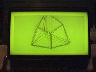
I have captured a video of the output of the circuit when running the demo which can be seen above. The horizontal grey lines are a limitation of my video capture card; these lines appear correctly as alternating black and white pixels on a real TV set! You can download the code for this demo from my site along with a PDF of the schematic. As this is a work in progress I'm sure there are plenty of bugs left to squash but I think it's getting there, slowly but surely!
dsPIC33 VDC with GLCD or PAL TV output
Sunday, 4th July 2010
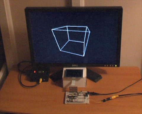
I have currently been using some terminal emulation software on my PC to see the output of the Z80 computer. It seems a little silly to rely on a large multi-gigahertz, multi-megabyte machine just to display the output from a machine at the megahertz and kilobyte end of the scale. I had previously done some work with a dsPIC33 to drive a 320×240 pixel graphical LCD so dug out its breadboard and dusted off the code to try to make something of it.
Inspired by John Burton's recent experiments with PAL TV output I decided that the first thing I should do is add support for TV output. The graphical LCD is nice but a little small and responds to pixel changes rather slowly, making animation very blurry.
I think the results are reasonably good. A lot of the code is shared with the old LCD driving code, which means that the LCD demos work fine with the TV too. Fortunately, retracing the TV is a much less CPU-intensive job than retracing the LCD. The PIC has an SPI peripheral that allows you to clock out eight or sixteen bits a bit at a time at a selected speed by writing to a single register, which is great for clocking out the pixel data on each scanline. Even better are the PIC's DMA channels, which allow you to output a selected number of bytes or words to a selected peripheral from a specified location in RAM with no CPU involvement; all I need to do on each line is to copy a complete scanline to the DMA memory, initiate a transfer from this memory to the SPI peripheral and the job is as good as done. Using the DMA hardware as opposed to writing to the SPI registers directly reduced the rendering time of the Mandelbrot fractal part of the demo from 33 seconds to 18 seconds.
One problem I haven't been able to resolve is that the PIC inserts a small delay between every DMA/SPI transfer, which results in every sixteenth pixel being a bit wider than the fifteen before it. This is especially noticed on dithered regions. If I write to the SPI registers directly this delay vanishes. I'm not sure if the picture quality increase is worth the loss of performance, so I'd rather find a proper fix for this! For the time being, here's a video of the demo as it currently runs:
The TV contains a 75Ω resistor to ground on its composite video input. Two resistors are used on two PIC pins to form a voltage divider to produce the required output voltages (0V for sync, 0.3V for black and 1V for white). When the TV is disconnected the output of the circuit is 3.3V (the supply voltage, equivalent to a logic "high") as there's no load resistance to pull it to the correct 0.3V (a logic "low"). This can be used to periodically check whether a TV is connected and to switch between the LCD and TV output modes.
The above is rather vague, and I would recommend Rickard Gunée's article entitled How to generate video signals in software using PIC for more detailed information! The code for the demo can be downloaded from my website for those who are interested.
Update: I've updated my code to use the SPI peripheral in slave mode and use a timer and output compare unit to generate the clock signal. This regular clock signal produces pixels of identical sizes the new code can be downloaded here.
Controlling a PG320240H-P9 with a dsPIC33FJ128GP802
Sunday, 21st March 2010
In a previous entry I mentioned that I had purchased a PG320240H-P9 graphical LCD. This is a 320×240 white-on-blue pixel display, and it does not have an on-board controller or RAM. To display something on it you need to constantly refresh it with picture data; in this instance, sending four pixels at a time, starting from the top left and working from left to right, top to bottom — a bit like the scanning pattern of a CRT monitor.
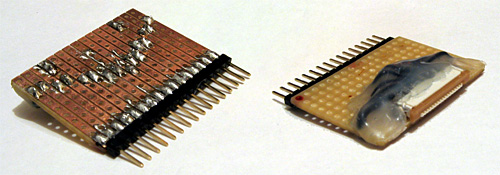
Connecting a circuit to the LCD is made slightly more tricky by its use of a 16-pin 1mm flexible flat cable. To get around this I soldered together an adaptor using a suitable FCC connector, pin strip, piece of stripboard and a fairly excessive quantity of hot melt adhesive. Even more tricky was the lack of a suitable datasheet for the LCD. After some digging I located this one for the PG320240WRM-HNNIS1 — it's slightly different, but contains timing diagrams and specifications that seem to work with the LCD I bought. One thing I still haven't worked out is the contrast adjustment; a 5K variable resistor between 0V and the relevant pin seems to have had the best results thus far. A helpful webpage, Graphical LCD controller for ST8024+ST8016 based displays, has a plain English description of how to drive the LCD, though as far as I'm aware the M pin should have its logic level toggled every frame, giving you a "glass" frequency of half of the refresh rate, not 200Hz-400Hz. The lack of a proper datasheet makes these things a little complicated!
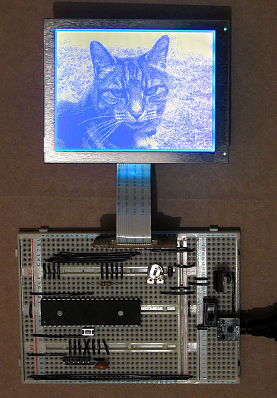
My first attempt to drive the LCD involved an ATmega644P, a microcontroller with 64KB of flash ROM and 4KB of RAM. The above photo shows it displaying a picture of a cat, which was stored in ROM and output using the following code:
#include <stdint.h>
#include <avr/io.h>
#include <avr/pgmspace.h>

#define LCD_FLM   (6)
#define LCD_M     (5)
#define LCD_C1    (4)
#define LCD_C2    (3)
#define LCD_D_OFF (2)

#define LCD_CONTROL_PORT (PORTC)
#define LCD_CONTROL_PIN  (PINC)
#define LCD_CONTROL_DDR  (DDRC)

#define LCD_DATA_PORT    (PORTA)
#define LCD_DATA_PIN     (PINA)
#define LCD_DATA_DDR     (DDRA)

#include "cat.h"

int main(void) {

    // Make control pins outputs.
    LCD_CONTROL_DDR |= _BV(LCD_FLM) | _BV(LCD_M) | _BV(LCD_C1) | _BV(LCD_C2) | _BV(LCD_D_OFF);

    // Make data pins outputs.
    LCD_DATA_DDR |= 0b1111;

    // Enable the LCD.
    LCD_CONTROL_PORT |= _BV(LCD_D_OFF);

    for(;;) {

        // Toggle the M pin to provide the LCD AC voltage.
        LCD_CONTROL_PIN |= _BV(LCD_M);

        const uint8_t* picture_ptr = cat_picture;

        // Scan 240 rows in the image.
        for (uint8_t row = 0; row < 240; ++row) {

            // Begin the line.
            LCD_CONTROL_PIN |= _BV(LCD_C1);
            LCD_CONTROL_PIN |= _BV(LCD_C1);

            if (row < 2) LCD_CONTROL_PIN |= _BV(LCD_FLM);

            // Send 40 eight-bit words.
            for (uint8_t column = 0; column < 40; ++column) {
                LCD_DATA_PORT = pgm_read_byte(picture_ptr) >> 4;
                LCD_CONTROL_PIN |= _BV(LCD_C2);
                LCD_CONTROL_PIN |= _BV(LCD_C2);
                LCD_DATA_PORT = pgm_read_byte(picture_ptr);
                LCD_CONTROL_PIN |= _BV(LCD_C2);
                LCD_CONTROL_PIN |= _BV(LCD_C2);
                ++picture_ptr;
            }
        }
    }

}
A 320×240 display has 76,800 pixels, and if you store each pixel as a single bit (so eight pixels per byte) you need 9600 bytes to store a complete frame, which clearly won't fit in the 4KB offered by the ATmega644P. Rather than upgrade to an AVR with more memory, I jumped to the dsPIC33FJ128GP802, a 16-bit microcontroller with 16KB of RAM. As well as quadrupling the RAM from the ATmega644P it also doubles the program memory (128KB from 64KB) and speed (40 MIPS from 20 MIPS). When working with AVRs I'd been using a slow home-made serial programmer, and rather than continue with this sorry state of affairs (lack of debugging capabilities is never fun, especially when it takes over a minute to program the microcontroller) I treated myself to a PICkit 3 Debug Express.
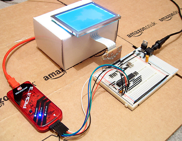
The above photo shows the LCD connected to the microcontroller as well as the PICkit 3. The dsPIC33FJ128GP802 requires a voltage supply from 3.0V to 3.6V, not the 5V I am used to, so to power it I have put two IN4001 rectifier diodes in series with the 5V regulator output. Each diode incurs a voltage drop of 0.7V, producing 3.6V for the rest of the circuit. The LCD is powered from the main 5V supply, but it seems happy with the 3.6V logic "high" from the dsPIC.
The LCD is connected to the dsPIC as follows:
- FLM to RB15
- M to RB14
- C1 to RB13
- C2 to RB12
- /D_OFF to RB11
- D0~D3 to RA0~RA3
A 10K resistor is included between /D_OFF and ground. This is very important, as it holds the /D_OFF line low when RB11 is floating (e.g. during reset), forcing the display off — if the display is powered, but is not being actively refreshed, the LCD panel can become overloaded and damaged.
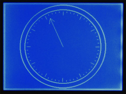
I have knocked together a simple demo that shows a few different graphics on the LCD. The LCD is constantly refreshed by an interrupt service routine that runs in the background, leaving some CPU time to the user program. As there is only enough RAM for a single frame buffer, animation has to be quite simple to avoid flickering, but I've still managed to include my favourite spinning cube.
The project can be downloaded here. I'm still getting to grips with the dsPIC series; the code is likely to be pretty awful, and I still have a problem where the dsPIC resets itself every couple of minutes (I'm not really sure if this is a software or hardware issue). Still, it's a start, and I hope that I can use this LCD as the display for my Z80 computer project.
Update: Having seen this post, the chap who originally suggested that I investigate the dsPIC33FJ128GP802 sent me an email with some advice, chiefly about my poor power supply, missing decoupling capacitors and use of an electrolytic capacitor on the VCAP pin. I have since replaced the two rectifier diode affair with a proper 3.3V regulator for the power supply, added a decoupling capacitor across AVDD/AVSS and moved the decoupling capacitor between VDD/VSS closer to the microcontroller. I have also ordered some tantalum capacitors to replace the electrolytic one. A bit of debugging found that the watchdog timer is responsible for the spurious resets; I have disabled it in the code for the time being, which has stopped the resets.
Z80 computer - Lines, cubes and inverted text
Sunday, 5th October 2008
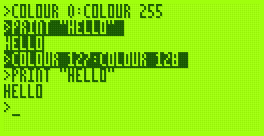
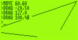
I've made a few additions to the operating system for the computer. The Console module, which handles text input and output, now supports "coloured" text - that is you can set the text foreground and background colours to either black or white. This functionality is exposed via the BBC BASIC COLOUR statement. If you pass a value between 0 and 127 this sets the foreground colour (0..63 is white, 64..127 is black) and if you pass a value between 128 and 255 this sets the background colour (128..191 is white, 192..255 is black).
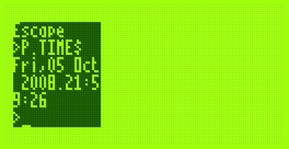
The image on the right also demonstrates another addition - you can set the text viewport to occupy a partial area of the display. This is most useful when coupled with the ability to define graphics viewports, which I have yet to add.
That said, I have started writing the Graphics module. So far all it can do is draw clipped lines, and this functionality is exposed via BBC BASIC's MOVE and DRAW statements. MOVE sets the graphics cursor position - DRAW also moves the graphics cursor, but also draws a line between the new position and the previously visited one.
I cannot use drawing code I've written for the TI-83+ version due to differences in the LCD hardware and the way that buffers are laid out. The popular way to lay out graphics buffers on the TI-83+ is as follows:
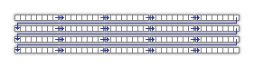
Each grey block represents 8 pixels - one byte in LCD memory represents 8 pixels grouped horizontally. The leftmost bit in each 8-pixel group is the most significant bit of each byte. The data is stored in the buffer so that each row of the LCD is represented by 12 consecutive bytes. This left-to-right, top-to-bottom arrangement should seem sensible to anyone who has worked with a linear framebuffer. However, due to the way that the LCD I'm using is arranged, I'm using the following buffer layout:
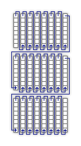
The LCD hardware groups pixels vertically, but when you write a byte to it its internal address pointer moves right. Furthermore, the most significant bit of each byte written is at the bottom of each group. This may sound a little confusing, but actually works out as more efficient. Writing text is easy; I'm using a 4×8 pixel font, so all I need to do is set the LCD's internal address counter correctly then write out four bytes, one for each column of the text (other sensible font sizes for the display, such as 6×8 or 8×8 are just as easy to display).
Another example of improved efficiency is if you deal with pixel-plotting routines. Each pixel on the display can be addressed by a buffer offset and an eight-bit mask to "select" the particular pixel in an eight-pixel group. With this arrangement, moving the pixel left or right is easy; simply increment or decrement the buffer offset by one. Moving the pixel up or down is a case of rotating the mask in the desired direction. If the rotation moves the pixel mask from one 8-pixel group to another (which only happens every eight pixels) the buffer offset needs to be moved by 128 in the correct direction to shunt it up or down.
On the TI-83+, moving the pixel up or down requires moving the buffer offset up or down by 12; moving the pixel left or right is a rotation as before with a simple buffer offset increment or decrement to move between 8-pixel groups.
In Z80 assembly incrementing or decrementing a 16-bit pointer by one is a single instruction taking 6 clock cycles; moving it by a larger offset takes at least 21 clock cycles, 42 if you include backing the temporary register such an operation would take.
What may be interesting to see is how well a raycaster would work on a system that has video memory arranged into columns.
Without wishing to be typecast as that programmer who loves spinning cubes, I also wrote a cube-spinning demo to test the line drawing routines as well as some integer arithmetic routines I've added (the Z80 can't multiply or divide, so these operations need to be implemented in software).
It runs fairly smoothly (bearing in mind the 2MHz clock speed). The second half of the video has the Z80 running at 10MHz; it actually seems quite stable even though the LCD is being accessed at nearly five times its maximum speed (the system did need to be reset a few times until it worked without garbling the display).
Text viewports and sprites
Monday, 21st July 2008
Back to work on the TI-83 Plus port of BBC BASIC! To complement the graphics viewport I've added support for text viewports — this lets you define the area the text console uses. The following VDU commands are now supported:
- VDU 24,<left>;<top>;<right>;<bottom>;
Define a graphics viewport. - VDU 28,<left>,<top>,<right>,<bottom>
Define a text viewport. - VDU 26
Reset both viewports to their default settings (full screen). - VDU 29,<x>;<y>;
Defines the graphics origin.

The above screenshots defines the graphics viewport to fill the left hand side of the screen and shunts the text viewport over to the right half, using the following code:
VDU 24,0;0;47;63;
VDU 28,12,0,23,9
VDU 29,24;32;
I've also added simple sprite drawing to BBC BASIC's PLOT command. PLOT usually takes a shape type and two coordinates, but for sprites (shapes 208..215) I've added an extra parameter - the address of the sprite data to use.

   10 DIM ball 7
   20 ball?0=&3C
   30 ball?1=&5E
   40 ball?2=&8F
   50 ball?3=&DF
   60 ball?4=&FF
   70 ball?5=&FF
   80 ball?6=&7E
   90 ball?7=&3C
  100 *REFRESH OFF
  110 REPEAT
  120   CLG
  130   T=TIME/100
  140   FOR P=0 TO 5
  150     A=P/3*PI+T
  160     X=16*SIN(A)+44
  170     Y=16*COS(A)+28
  180     PLOT 213,X,Y,ball
  190   NEXT
  200   *REFRESH
  210 UNTIL INKEY(0)<>-1
  220 *REFRESH ON
The above code allocates 8 bytes of memory (DIM ball 7) then copies the sprite data to it by use of the ? indirection operator. This is a little laborious, so in reality you'd probably store your sprites in a binary file external to the main program, and might load them like this:
   10 ball%=FN_loadSprite("SPRITES",0)
   20 face%=FN_loadSprite("SPRITES",1)
   30 *REFRESH OFF
   40 REPEAT
   50   CLG
   60   T=TIME/100
   70   FOR P=0 TO 5
   80     A=P/3*PI+T
   90     X=16*SIN(A)+44
  100     Y=16*COS(A)+28
  110     PLOT 213,X,Y,ball%
  120   NEXT
  130   PLOT 213,44,28,face%
  140   *REFRESH
  150 UNTIL INKEY(0)<>-1
  160 *REFRESH ON
  170 END
  180 DEF FN_loadSprite(f$,i%)
  190 fh%=OPENIN(f$)
  200 PTR#fh%=i%*8
  210 DIM spr 7
  220 FOR j%=0 TO 7
  230   spr?j%=BGET#fh%
  240 NEXT j%
  250 CLOSE#fh%
  260 =spr
  270 ENDPROC
(Note FN_loadSprite() at the end of the program). The result is the following:

Next up: drawing text at the graphics cursor position (as sprites).
Clipped graphics and ellipses
Monday, 23rd June 2008
qarnos — author of the superb Aether 3D engine — has been lending a hand with the BBC BASIC graphics API and contributed a large amount of very useful code.

First up is some code to clip 16-bit line coordinates down to 8-bit coordinates. This allows for lines to be partially (or completely) off the screen.


He's also written a fast ellipse drawing and filling routine. The ellipses are also clipped to the viewport and are filled with an 8×8 pixel pattern.

The graphics viewport can be redefined using the VDU 24,left;top;right;bottom; command as demonstrated in the above example.


GCOL can also be used to set a plotting mode; either plotting the specified colour directly, performing a logical operation (OR, AND, EOR) or inverting the existing colour.

All but the last of the above screenshots are the result of running BBC BASIC on a TI-83+ SE at 15MHz. The final screenshot is running at the regular 6MHz.
Gyrating cubes in BBC BASIC
Thursday, 12th June 2008
Work has been keeping me busy recently, but I've tried to set aside a small amount of time each evening to reclaim some sanity and do a little work on BBC BASIC. Not much progress has been made, but there has been some at least.


On the left is the program running on an 83+ SE at 15MHz, on the right on the regular 83+ at 6MHz. If you really wanted to do 3D in BBC BASIC you could probably get away with writing some of the more expensive operations — such as transforming/projecting vertices in batches — in assembly, but that would sort of go against the whole point of trying to write a program to test the speed of BASIC. 
Here's the rather naïve code:
   10 *REFRESH OFF
   20 DIM p%(15)
   30 fps%=0
   40 lfps%=0
   50 fpst%=TIME+100
   60 REPEAT
   70   rX=TIME/300
   80   rY=TIME/400
   90   SrX=SIN(rX)
  100   CrX=COS(rX)
  110   SrY=SIN(rY)
  120   CrY=COS(rY)
  130   pt%=0
  140   FOR x=-1TO1STEP2
  150     FOR y=-1TO1STEP2
  160       FOR z=-1TO1STEP2
  170         tX=y*CrX-x*SrX
  180         tY=-x*CrX*SrY-y*SrX*SrY-z*CrY
  190         tZ=3-x*CrX*CrY-y*SrX*CrY+z*SrY
  200         p%(pt%)=tX*40/tZ+48
  210         pt%=pt%+1
  220         p%(pt%)=tY*40/tZ+32
  230         pt%=pt%+1
  240       NEXT
  250     NEXT
  260   NEXT
  270   CLG
  280   PRINTTAB(10,0)lfps%" FPS"
  290   MOVE p%(0),p%(1)
  300   DRAW p%(4),p%(5)
  310   DRAW p%(12),p%(13)
  320   DRAW p%(8),p%(9)
  330   DRAW p%(0),p%(1)
  340   DRAW p%(2),p%(3)
  350   DRAW p%(6),p%(7)
  360   DRAW p%(14),p%(15)
  370   DRAW p%(10),p%(11)
  380   DRAW p%(2),p%(3)
  390   MOVE p%(4),p%(5)
  400   DRAW p%(6),p%(7)
  410   MOVE p%(12),p%(13)
  420   DRAW p%(14),p%(15)
  430   MOVE p%(8),p%(9)
  440   DRAW p%(10),p%(11)
  450   *REFRESH
  460   fps%=fps%+1
  470   IF TIME>fpst% THEN lfps%=fps%:fps%=0:fpst%=TIME+100
  480 UNTIL INKEY(0)<>-1
  490 *REFRESH ON
  500 END
I have also added support for the COLOUR statement (for changing the text foreground and background colour) and copy key editing.


Copy key editing, as demonstrated in the screenshot on the right, lets you break the text input cursor into two parts - a write cursor (which is left behind on the line you were editing) and a read cursor, which can be positioned anywhere on the screen. Pressing the copy key (in this case, XTθn) reads a character under the read cursor and writes it to the write cursor, then increments both.
One feature that's a bit more fun is the support of device files. This is a way of accessing external devices as if they were files. For example, by opening the file AT.DEV you can read and write bytes using the AT protocol (used by AT and PS/2 keyboards and mice) using BBC BASIC's built-in file manipulation routines.

You could use this to do something useful, or could just use this to flash the LED on a keyboard back and forth.
   10 keyb%=OPENOUT"AT.DEV"
   20 DATA 2,4,1,4,-1 : REM LED flash pattern (-1 terminated).
   30 REPEAT
   40   READ l%
   50   REPEAT
   60     PROC_setled(l%)
   70     PROC_pause(30)
   80     READ l%
   90   UNTIL l%=-1
  100   RESTORE
  110 UNTIL FALSE
  120 END
  130 :
  140 DEF PROC_flushin
  150 REPEAT
  160   IF EXT#keyb% d%=BGET#keyb%
  170 UNTIL NOT EXT#keyb%
  180 ENDPROC
  190 :
  200 DEF PROC_setled(l%)
  210 BPUT#keyb%,&ED
  220 PROC_flushin
  230 BPUT#keyb%,l%
  240 PROC_flushin
  250 ENDPROC
  260 :
  270 DEF PROC_pause(t%)
  280 start%=TIME
  290 REPEAT UNTIL TIME >= start%+t%
  300 ENDPROC
ASCII Madness II and Tutorials
Friday, 5th August 2005
Well, it's been a long time - here are two updates in one!
First up, ASCII Madness II. It's a text-mode scene demo that runs in the Windows console using characters from the extended ASCII set to produce the effects.
You can download it (and the source) from here.
Next up are some simple tutorials. Oldschool graphics stuff, I'm afraid, but hopefully someone will find them of interest. They are presented in the form that I would have liked to have read... and I know that I'm not very conventional in my learning style.
I'd be interested to see if the demo apps (blobs, tunnel) work fine - I've had one complaint that they can't find a particular DLL, which is a bit odd.
Subscribe to an RSS feed that only contains items with the Spinning cube tag.