Bank-Switching Memory and I2C
Thursday, 11th September 2008
Cheers for the comments.  As EasilyConfused pointed out, I have done calculator programming in the past, which makes this much easier - learning Z80 assembly to program a calculator influenced the choice of CPU in this computer, and porting BBC BASIC to the calculator showed that with a minimal amount of code to sit between it and the hardware you'd have a decent operating system with very little work. And if a Terminator-related name is good enough for the UK military, it should be good enough for this project...
The I/O board from a few posts ago has undergone a few revisions:
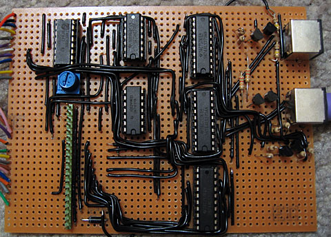
Both PS/2 ports are now fully wired up, though only the lower one is currently used by the OS for keyboard input. I will need to adjust the AT protocol routines (the AT protocol is used to control both keyboard and mouse) to support multiple physical ports, as it was adapted from code I wrote for the TI-83+ calculator and as such only supports one device at a time. The mouse position will be polled by calling ADVAL(axis%), which on the BBC Micro would return the joystick position (axis% specifies the type of information to retrieve from the mouse - a value of 0 returns the buttons as a bitfield, 1 returns the movement in the X axis, 2 the movement in the Y axis and 3 the amount the scrollwheel has been scrolled).
At the very bottom of the circuit board is another 8-bit latch. This is for the (currently) write-only control port. The three least significant bits specify the current ROM page (one of eight 16KB ROM pages can be swapped in for a total of 128KB) and the next bit specifies one of two 16KB RAM pages accessible in the $4000..$7FFF address range. One of the other bits will be used to switch the LCD backlight on and off in software, one more may be connected to a buzzer, and I'm sure I can find some use for the last two. As it's write-only, its current state needs to be stored in RAM so that you can change bits of it (eg when changing the ROM page you wouldn't want to change the backlight status at the same time; you'd need to retrieve the current state and mask in the bits you wish to preserve). This is obviously an ugly hack, and I'm hoping I'll be able to use some of the space to the right of the latch IC on the circuit board to add the other latch to allow the port to be read as well (an I/O port needs two latches - an output latch that takes data from the data bus and outputs it to external hardware, and an input latch that takes data from external hardware and puts it back on the data bus).
The first test of the new ROM paging hardware was to display a simple animation. Assuming 1KB on each ROM page was taken up by the animation playback program, that leaves 15KB per ROM page. A frame (128×64 pixels) is 1KB, so that's 15 frames per page, or 120 frames total. I converted a clip from Pink Floyd's Arnold Layne music video to a suitable format and wrote a playback routine that could run from RAM. When the computer booted it would copy the player to RAM and run it from there as it could then run uninterrupted when different ROM pages were swapped in to read the frame data.
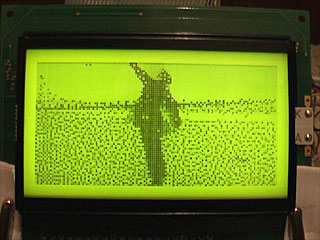
An animation like this is a useful test, as if the ROM paging didn't work properly (simulated by holding the three ROM page selection lines low) the software would still run, but would just loop the first 15 frames (or play chunks of 15 frames out of sequence) instead of crashing.
Another addition to the circuit above is the cluster of discrete transistors and resistors under the lowest PS/2 port. This is the same sort of pair of open-collector I/O data lines that drive each PS/2 port, except that the two data lines are fed out of the I/O board and back to the breadboard that's currently sitting between the memory board and the I/O board to these two simple 8-pin chips:
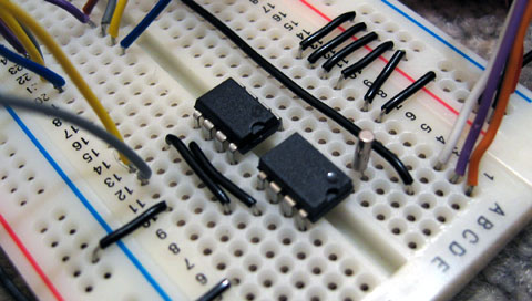
This is the I2C bus, a simple, low-speed, two-wire bus that will allow other components be easily connected to the computer. The I2C protocol is implemented in software. The two chips in the above image are a DS1307 real-time clock (foreground, with quartz crystal) which I hope to use for timing purposes and a 24LC256 32K×8 EEPROM which I hope to use for file storage. I would need to have some way of accessing the I2C bus externally (to plug in EEPROMs as removable storage) as well as supporting the internal devices.
I haven't yet done any work on supporting I2C devices properly, but I have added I2C bus emulation to the emulator I'm using to develop the OS. BBC BASIC will pass commands prefixed with a *STAR to the operating system, so I've added a *I2CPROBE command that will hammer through all available addresses and list any devices that acknowledge a write request.
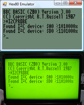
$A0 is the EEPROM and $D0 is the clock.
I think I may have dug myself into a hole for CPU timing. I mentioned that I will need to drop the CPU clock to 2MHz when accessing the LCD; unfortunately, switching between 2MHz and 10MHz doesn't seem to work very well. I can run the system relatively stably at either speed (though at 10MHz data sent to the LCD is occasionally corrupted) but if I try and switch dynamically (eg switching from the 10MHz to the 2MHz clock when /IORQ goes low to indicate an I/O request) the system locks up. My assumption is that during time it takes the logic gates that perform the 10MHz/2MHz switch to properly settle into their new state (which is in the tens of nanoseconds) the clock signal stutters a little, effectively producing a clock signal (albeit a brief one) well over 10MHz. I don't have an oscilloscope to verify this, however. 