A primitive 3D engine for the TI-83+
Sunday, 17th October 2010
As you may have guessed from the number of spinning cubes in my projects, I am quite fond of primitive 3D. As you may also have guessed from the number of TI-83+ calculator projects I have undertaken, I'm also quite fond of programming on low-end machines. I have never really successfully put 3D and the TI-83+ together, though.

One way to build a 3D world in software is raycasting (e.g. Wolfenstein 3D). This typically results in blocky worlds where all walls are at 90° angles to each other. There are several games using raycasting engines on the TI-83+ already; they are much faster and better-looking than my sorry attempt pictured above.

Another method is to use true 3D geometry (e.g. Quake). Many years ago I attempted to work on something that looked a little like Quake. I built this on the Matt3D engine, which supported basic 8-bit coordinates and lines, but not solid objects. The result was even less useful than the above raycaster!

Another method somewhere between the two is a "2.5D" engine, where level geometry is defined between points in 2D space but projected in 3D (e.g. DOOM). This allows for walls that are not at 90° angles to each other, whilst simplifying the rendering procedure significantly. I spent some weeks working on such an engine a few years ago yet never managed to get any further than the above screenshot. As you can probably tell from the fact that you can see the walls through each other I never found a good way to handle occlusion, and the project ended up stagnating.
Looking for a quick weekend project I thought back to the work I'd done with the DOOM and Quake engines. These engines use a BSP tree structure to sort the level geometry for rendering. I reckoned that if simplified a little a similar tree structure could be used to render a 3D world on the TI-83+ calculator. The four screenshots above show that this technique is indeed quite successful. My implementation could certainly do with a lot of work but I think the theory is at least sound.
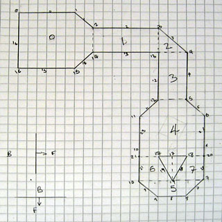
I decided that one way to make this project a bit more fun was to set myself a challenge; to design a level that I would, ultimately, be able to walk around in. This level is shown above, and contains a number of walls that are not parallel to the X or Y axis and a pillar. I have split the world into eight convex "sectors" (labelled 0 to 7) with a dotted line between them to show where the BSP tree is partitioned. All of the partitions are either horizontal or vertical to speed up tree traversal; the TI-83+'s Z80 CPU does not support floating point arithmetic, let alone multiplication or division, so being able to decide which side of a partition you're on quickly is very useful.
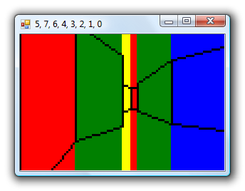
Rather than dive straight into Z80 assembly programming I knocked together a quick prototype in C#. This allows for quick and easy debugging; the blocks of colour allow me to quickly identify walls and the application title bar contains the order in which the sectors have been rendered. These can then be checked against the version running on the TI-83+ in case there are problems.

With the C# version running satisfactorily I started converting it to Z80 assembly. The above screenshot shows the first step; transforming the level's vertices around the camera. Clicking on the screenshots will take you to an animated version; as some of them are quite large I have linked to them rather than embedding them directly.
The next step was to traverse the BSP tree. The numbers across the top of the screen indicate the order in which to render the sectors, from back to front — however, due to a simple bug, they are actually listed from front to back. This was fortunately very easy to fix.
Walls are connected between the vertices, so I quickly threw something together to display all of the walls on the screen. The walls will have to be clipped against the camera's view (or discarded entirely if they are outside the view) so being able to see them is a great debugging aid!
We are only interested in drawing walls that are in front of the camera, so the first bit of clipping code deals with clipping the walls against Y=0.

The above screenshots show the final three stages of clipping to the camera's view, defined by Y>0, Y>+X and Y>-X. The first screenshot shows culling of any wall that does not satisfy this in any way; walls that are completely outside the view are discarded. The second screenshot shows walls being clipped against Y=+X, and the third finally adds clipping against Y=-X. The lack of hardware floating-point arithmetic makes the code fairly slow and ugly but it does seem to be working relatively well.
We are only really interested in dealing with walls that are facing the camera; we don't want to draw the back of walls. To work out which we want to keep and which we want to ignore, we project the wall to the screen and check whether its projected start vertex appears to the left or the right of its end vertex.
A simple perspective projection is performed to turn this clipped 2D world into what appears to be a 3D one. The X coordinate of each vertex is divided by its Y to get the X coordinate on-screen and the height of the wall is divided by the vertex Y to get the Y coordinate on-screen. The left screenshot shows the top and bottom of wall edges; the right screenshot adds lines between the floor and the ceiling to produce a more convincing "wireframe" view of the world.

The final step is to make the world appear solid, by hiding walls that are far away behind walls that are closer to us. Traversing the BSP tree gives us the order in which to draw the walls, so all that is required is to draw solid quadrilaterals for each wall rather than the lines around its outside. A fast clipped quadrilateral filler would take me some time to write so I cheated by drawing a solid white rectangle the width of the wall and the height of the entire screen before drawing the wall outlines. As the camera is half-way up each wall and all of the walls are the same height there are no cases where a foreground wall only partially covers a background one so this trick works for the time being.
I'm glad I achieved my goal of walking around the 3D world I'd sketched in pencil at the start of the weekend but I'm not sure where I'll be able to take the project now. Turning it into a useful 3D engine for a game would certainly require a lot of work. The level and its BSP tree were generated by hand, which would not lend itself well to anything but the simplest of levels. However, the lack of variation in wall heights produces fairly dull levels in any case; DOOM-style levels would be something to strive for, but I'm not sure how well the calculator would be able to cope with them. I'm also unsure how well the engine would scale; this very primitive version only achieves around 12 FPS on a 6MHz TI-83+. It's certainly given me something interesting to think about!
If you would like to try the program on your calculator, please download Nostromo.8xp. It requires an Ion-compatible shell to run. It is very primitive, likely to be quite buggy (you may encounter rendering bugs when very close to walls due to integer overflow in the clipping and projection code) and may well crash your calculator; please back up any important files before running it. Use the arrow keys to move around, Trace and Graph to strafe and Clear to quit.