Using a Master System Light Phaser in Mega Drive Menacer games
Wednesday, 18th March 2020
I'm a big fan of light gun games and have guns and games for most of the Sega systems – the Master System's Light Phaser, the Saturn's Virtua Gun and the Dreamcast's gun all get plenty of use.
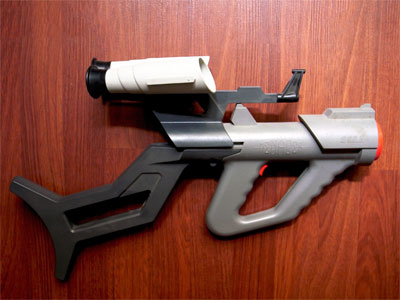
One notable omission is the Sega Mega Drive and its Menacer light gun. This is a wireless gun with a range of bulky plastic accoutrements that represented Sega's efforts in the 16-bit generation; unfortunately only three games were released for it on the Mega Drive – a six-in-one collection of minigames that came bundled with the gun, a port of T2: The Arcade Game and the ferociously-expensive Body Count.
Ultimately the gun was a flop and they are not cheap to pick up second-hand (and are often missing most of the bits) so I haven't sought one out, however I did recently buy a cheap job lot of games which included a loose copy of T2: The Arcade Game.
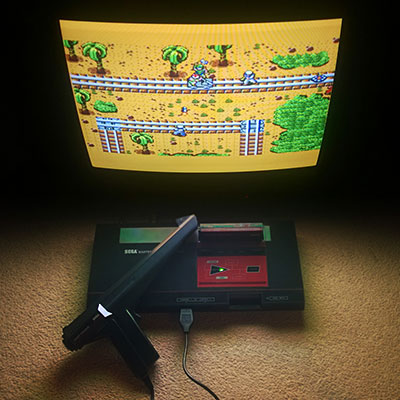
I tried the game with the regular control pad and found it a disappointing experience (as most light games are when played with a pad!) so thought I'd see if I could get it to work with one of my Master System Light Phaser guns.
Of course, the game wouldn't detect that the gun was plugged in. Controllers on the Master System were generally very simple affairs, with one pin on the controller port per button (no multiplexing or serial data transfers here). On the regular control pad four data lines were used for the d-pad directions and two data lines (TL and TR) were used for the two buttons. These data lines were pulled high by the console and the control pad just contained switches that connected these data lines to ground when pressed for simple active-low logic.
The Light Phaser doesn't make use of the four d-pad data lines and only has one button so only uses one of those two data lines (TL) however it does make use of another pin on the controller (TH) for its light sensor. When this pin goes low the console latches the video chip's horizontal counter and the game software can read this and the free-running vertical counter to determine what point on the screen the console was outputting at the point the gun "saw" the light from the TV (and from this work out where the gun is aiming).
The Sega Light Phaser being used to play Rescue Mission on the Master System.
The Mega Drive is descended from the Master System's design and has very similar controller ports. The d-pad's four data lines are named DATA0 to DATA3, and by default the B and C buttons are mapped to the two TL and TR inputs like the two buttons on the Master System controller. However, the Mega Drive controller adds two extra buttons (A and Start). These two extra buttons share the TL and TR data lines and whether they are B and C or A and Start depends on the state of the TH line which is configured as an output from the console.
This use of the TH line to choose which buttons are mapped to which data lines is also used for controller identification. When TH is high the d-pad is mapped to the four data bits as normal. However, with a normal controller, when TH goes low data lines 2 and 3 (corresponding to left and right) go low also. This is normally impossible, as you can't physically press left and right simultaneously on a Master System controller, so a controller that ignores the state of the TH line won't be detected as a Mega Drive controller.
The device ID is encoded as a four-bit value according to the following logic:
| ID bit | TH state | Data bits |
|---|---|---|
| 3 | High | 3 OR 2 |
| 2 | High | 1 OR 0 |
| 1 | Low | 3 OR 2 |
| 0 | Low | 1 OR 0 |
For example, to read a regular controller's ID set TH to high and read the data lines. In this state the d-pad is mapped to the data lines. Bits 3 and 2 are mapped to to right and left. If neither is pressed both bits will be "1" as the inputs are active-low; 1 OR 1 is 1. If either left or right is pressed then one of the bits will be "0" but the other will be "1"; 0 OR 1 is also 1. The only way to get a zero is if both directions are pressed simultaneously which is not possible, so ID bit 3 will always be 1.
The same applies to ID bit 2, as this is uses data lines 1 and 0 which are mapped to the down and up buttons, so this will also always be a 1.
After setting TH low, we know that data lines 3 and 2 are forced to 0 so ID bit 1 is a 0.
Finally, ID bit 0 is based on data lines 1 and 0 which are still mapped to down and up and so will still be a 1. This all gives us a device ID of %1101, which is indeed the peripheral ID of a standard Mega Drive controller.
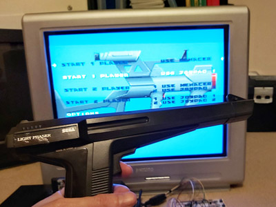
This is fine, but what does it mean for the Menacer? Well, that device has an ID of %0000. For this to happen we need to make sure that all four data lines are low whenever the console is reading the device ID. The easy way to do this is to take apart a Master System controller and to press all four d-pad buttons down simultaneously – doing so and starting the console with the T2 cartridge inserted makes the game think that a Menacer is plugged in!
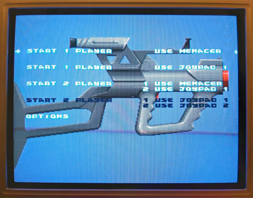
The Use Menacer options are white and selectable.
Somewhat unusually the Menacer's four buttons are mapped to the four data lines (instead of TL/TR) and are active high which means that if I start the game and let go of one of the Master System controller's buttons then it thinks I've pressed one of the Menacer's buttons (for example, releasing the "down" button makes DATA1 go high and the game thinks I'm pulling the trigger). Of course, I can't aim in this mode as there's no light gun input but it's good to see something is working!
I assumed that if TH is normally used for device identification I would start experimenting with using that to determine when the adaptor should output all zeroes. Considering the buttons need to be inverted to active-high logic too I thought it best to use an AND gate on each button so that if TH is high (normal state) the button input would pass through to the data line, but if TH is low (detection state) the data line would be forced low. I wired this up with an AND gate and four push buttons and the game still detected a Menacer and pressing a button in-game would now fire the weapon. Seeing that this worked, I removed one of the four push buttons that was previously used for the trigger button and used the TL data line from the Light Phaser instead via an inverter:
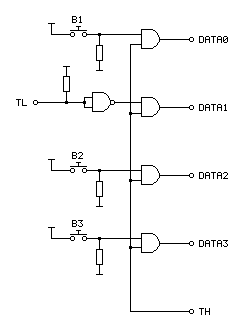
In the diagram above the TL on the left comes from the Light Phaser and the connections on the right go to the Mega Drive.
I assumed that the Menacer would also use the console's TH input for the light sensor from the gun (similar to the Light Phaser) so tried wiring up the Light Phaser's TH output to the Mega Drive's TH input. Moving the gun around the screen moved the aiming cursor around. Unfortunately, the aim was pretty far off:
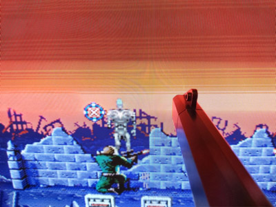
The blue cursor should be under the gun, which is touching the screen.
The game placed the aiming cursor a consistent distance left of where the gun really was aiming. I assumed this was due to the game expecting a delay between when the gun saw the light from the screen and it sending a pulse to the console – unlike a wired gun that can send the signal back to the console very quickly the wireless Menacer converts the detected light pulse into an IR pulse that then needs to be handled by the receiving unit plugged into the console. By the time the console sees this pulse it will have moved further along the current scanline (right), so the game software works backwards (left) to an earlier point on the scanline. As I'm using a wired gun that transmits the signal much more quickly this left offset causes the aim to be incorrect.
The solution to this is to introduce our own delay into the signal, which I did with a crude RC circuit:
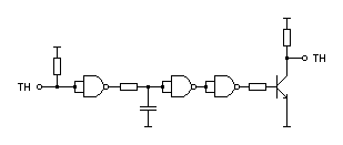
As I'd previously used a NAND chip to invert the signal from the trigger button I used three more of its gates to implement the delay. The first gate buffers the signal as the gun's TH is a common emitter output, so either connected to ground or pulled high via a resistor. This buffered signal then charges or discharges a capacitor to ground via a resistor – this provides most of the delay, and in my testing a 220Ω resistor and 100nF capacitor provided better aim. The next two gates buffer the signal again before driving a transistor for a common emitter output – as the console is also driving the TH line as an output I didn't want to directly drive it from the adaptor circuit and so the transistor seemed safer and is how the Light Phaser works anyway.
This is a crude circuit and has its limitations (very short pulses could be dropped entirely rather than delayed, for example) but it does at least seem to greatly improve the aim:

The cursor now lines up with the point on the screen the gun is touching.
The game is now fairly playable, though there is one notable flaw with the circuit: pressing any button at the main menu screen causes the game to assume the gun has been disconnected, disabling the Menacer options:
The Use Menacer options are dark and no longer selectable.
Clearly using the TH signal alone to disable the buttons is insufficient, we must need to also output 0 when TH is high for full compatibility with the peripheral ID reading and the gun must use some other technique to enable or disable the button data.
Fortunately, a copy of the Menacer patent can be downloaded from the Sega Retro website where it can be studied to see if it provides any more clues for how the Menacer works. It goes into some detail about how the gun communicates with the console, including this figure showing the gun:
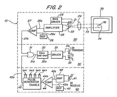
The centre portion of the image shows that infra-red signals from the gun are transmitted to the receiver in the form of 10µs pulses. The top portion of the image shows that these pulses can be generated by the gun's light sensor, so whenever the gun sees light it will send a 10µs IR pulse to the receiver. The bottom portion of the image shows the pulse generator used to encode the button presses; the button state is interpreted as a binary number and a corresponding number of IR pulses are sent: if SW1 is pressed then 1 pulse is sent, if SW2 is pressed then 2 pulses are sent, if SW3 is pressed then 4 pulses are sent and if SW4 is pressed then 8 pulses are sent. If multiple buttons are pressed then their values are added, so if SW1 (1) and SW3 (4) were pressed then five pulses would be sent up to a maximum of 15 pulses for all four buttons being pressed.
These button press pulses are only sent back to the console receiver after the gun receives an IR pulse from the receiver.
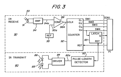
The receiver uses a counter chip to convert the IR pulses from the gun into button press or detected light pulses for the console. The duration of reset pulses are important here. The patent describes a standard counter reset pulse as being 2-3µs long and a main reset signal pulse as being about 10µs long. Any short reset pulse will reset the counter chip and latch. A long reset pulse will stil reset them, but also trigger a pulse of IR via the transmitter section at the bottom of the diagram. This IR pulse will cause the gun to send its button data back to the receiver, where the pulses will be counted by the counter chip and drive the DATA0 to DATA3 pins. After a certain delay to ensure that all button states have been sent the game software can read the button state and reset the counter, ready to read pulses from the light sensor in the gun. Bear in mind that the button state will have to be read before the active display starts, as the gun always sends an IR pulse when it sees light and this will cause the button presses to be miscounted.
Rather than pass every single detected pulse of light from the gun to the console it looks like the counter is used to detect eight pulses, after which it triggers a latch. This appears to be due to the assumption that when the gun is an expected distance away from the TV it will trigger on around 20 scanlines, and so by waiting for eight it will place the detected position roughly in the middle of those 20 lines.
All in all, this is a simple enough system but what does it mean for our convertor circuit? Will we need to add extra pulse length detectors and counters to make sure we send through the right sort of data?
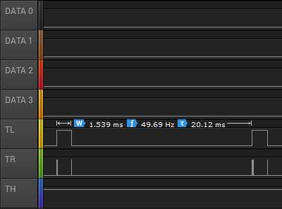
I captured the state of the controller port lines during gameplay and found the above logic traces. Each frame TL goes high briefly and is then low for the active part of the frame. Pin TR has very brief pulses, and these appear to be the reset pulses. If we zoom in, we can see these more clearly:
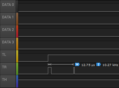
Here TR goes high for over 10µs and so must be the main reset pulse (used to read the button state) and the next pulse is around 3µs and so must be the regular counter reset pulse. The gap between these pulses is only 85µs, however – if the button IR pulses are 10µs long then this would not give us enough time to read them – even if there was no gap between them 15 pulses of 10µs would take 150µs. Either there is a delay of at least 85µs before the gun starts sending the button data or the timing is different in the real gun when compared to the patent information. There is a final 3µs reset pulse as TL falls and this pulse comes 1.435ms after the previous short reset pulse so that would provide plenty of time to receive the button press data before resetting the counter ready to detect light pulses.
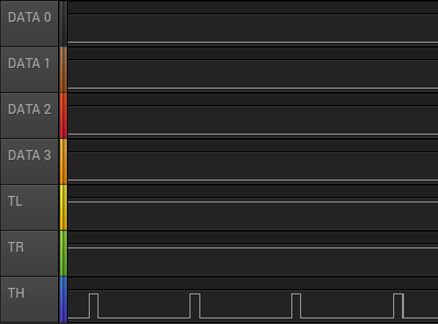
The next bit of the puzzle is what happens during the main menu when the Menacer is being detected. The traces are shown above. Both TL and TR are fixed high during this process. If we assume TR alone is used to reset the counters then holding this high would fix the data lines at %0000, identifying the controller as a Menacer. The TH line is also being pulsed here, possibly as the code is still checking to see if it could be some other type of controller.
If we force the output of the data lines to be 0 when TR is high (acting as a reset) then maybe this would work more reliably (and correctly) than when TH is low. I'll need to perform some further experiments, and also see whether the lack of the eight scanline delay before triggering the TH line to indicate detected light causes any other problems. I like the idea of a simple device that only uses logic chips to adapt the gun but if we need a more sophisticated circuit to time reset pulses and offset the vertical position maybe it would be better to switch to a microcontroller circuit. If that was the case, maybe the adaptor could also be programmed to work with games that use the Konami Justifier, another Mega Drive light gun that is incompatible with the Menacer.
If you'd like to see the circuit in action, I've uploaded a quick video on YouTube to accompany this post.