Adding sprite objects to the 3D world
Tuesday, 2nd November 2010
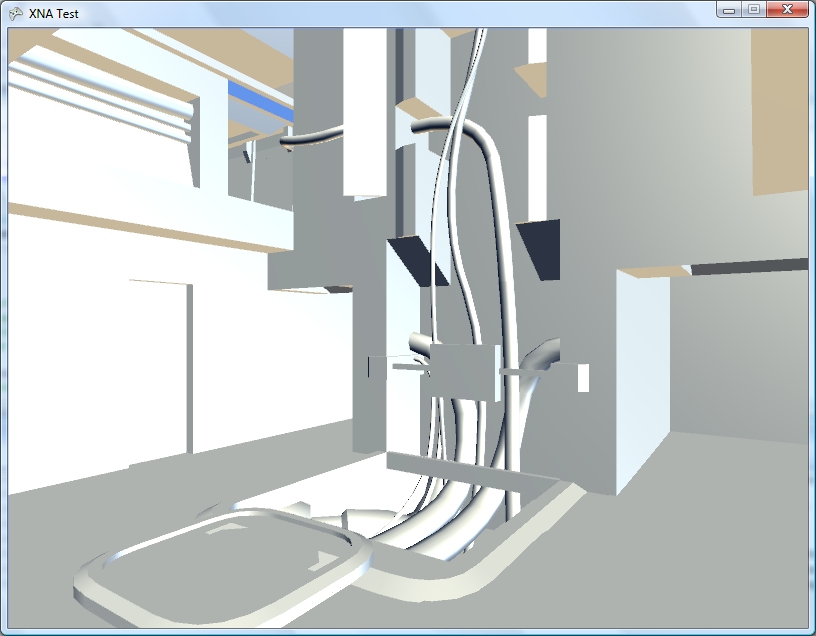
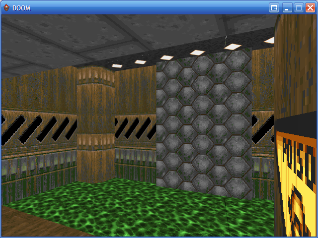
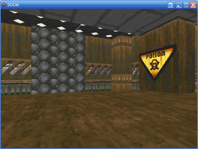
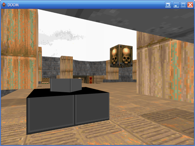
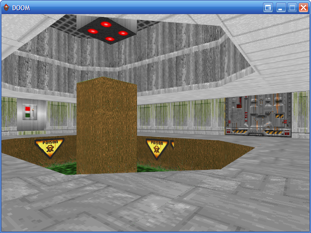
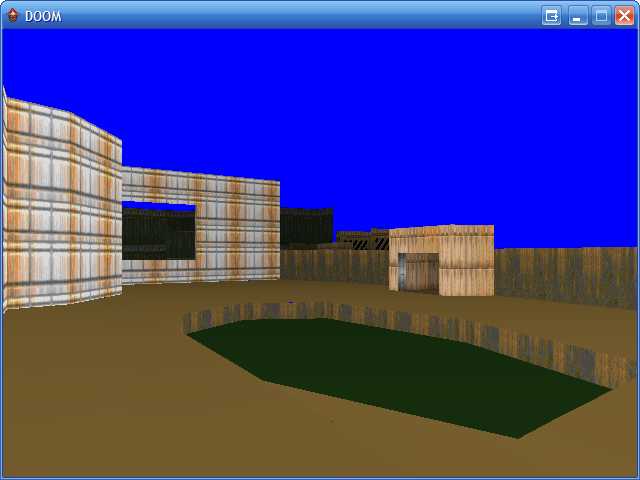
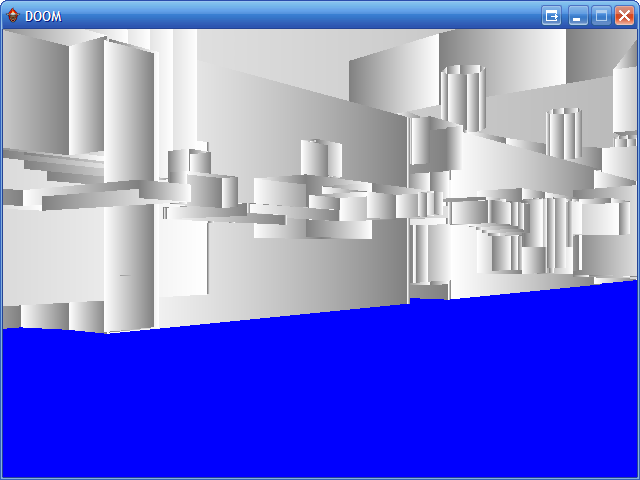
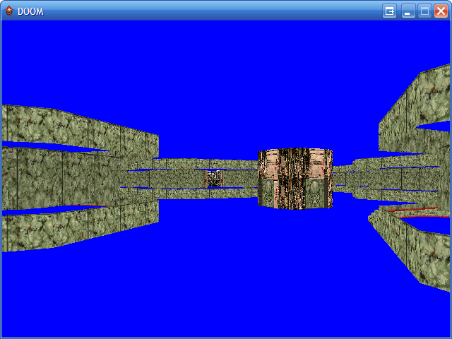
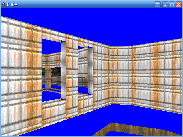
The previous entry showed a room from a map copied from DOOM's E2M7. I have since added the adjacent room:
It may not look as interesting as the other room but it is significantly more costly to render due to the sheer number of lines visible at a time in it. Looking across it from the far corner dropped performance down to around 2 FPS on the 6MHz TI-83+, which was really not a very good effort. I spent a fair amount of time over the weekend trying to optimise the code as much as I could, and manage to bring the frame rate in the player's starting position from 6 FPS up to the target 10 FPS. Looking across the length of the new room still dropped the framerate to around 4 FPS at 6MHz, but it's a start.
Once the engine had been made a little faster it seemed a good idea to slow it back down again by adding a feature. I had been pondering how to add objects in the form of scaled sprites to the world. Working out where to put them on the screen isn't so difficult, but clipping them against the world geometry so that they couldn't be seen through walls is another matter entirely. One way that seemed popular is to draw the objects in reverse depth order (drawing the sprites that were further away before those that were closer) and using a depth buffer for the world geometry to clip each pixel of the sprite against the world. This would take up a lot of memory on the calculator and run very slowly (populating the buffer with a depth value for each pixel would be a very expensive operation, as you'd have to interpolate depth values between the ends of walls and edges of floors).
The engine makes use of three per-column clipping tables when rendering the scene. One keeps track of columns that have been completed (usually by drawing a "middle" wall to that column); once completed no more pixels may be drawn to that column. The other two tables are used to define the upper and lower clipping bounds. At the start of the scene these are reset to the top and bottom edges of the display. As the world is rendered from front-to-back these regions are reduced to clip geometry that is further away against geometry that is nearer (think of looking through a hole in a wall — things that are further away from you will never be drawn in the space above or below that hole).
Fortunately, you can use this clipping information to clip sprites against the world geometry too. Each sprite object needs to be associated with a convex subsector. These subsectors are made up of walls and are drawn from front-to-back (sorted by the BSP tree) as the world is rendered. Before each one of these subsectors is drawn it is checked to see if it contains any sprite objects — if it does, the current clipping buffers and a reference to the subsector are pushed onto a stack. When all of the walls and floors have been drawn this stack contains a list of all of the subsectors containing sprites and the clipping regions used to draw those subsectors in front-to-back order. Stacks are Last In, First Out structures and so when you pull the data back out of this stack you end up retrieving a list of sprites to draw and the associated clipping regions in back-to-front order. This allows you to effectively unwind the clipping operations, so as you draw the sprites from back-to-front you can gradually enlarge the clipping regions in the opposite order to the way that they were reduced when drawing the walls. You would still need to sort the sprites manually from back-to-front within each subsector, but for the time being I've limited myself to one sprite per subsector for ease of development.
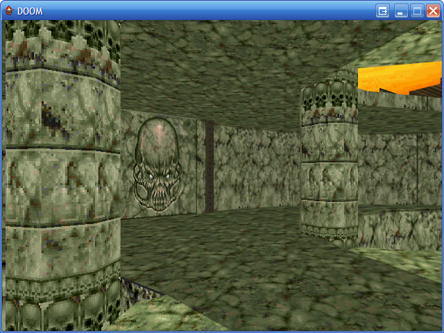
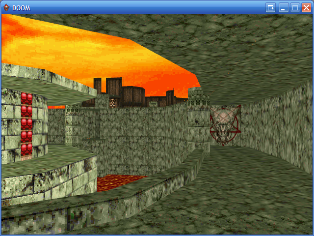
The above screenshots demonstrate an initial test of the "things" (as they are apparently technically called), rendering them as solid black squares.
Scaled sprites tend to be more useful than solid black squares, however, so here are a pair of candlesticks (well, that was the intention at any rate; call them cacti if you must). The sprite was simply ORed to the display, so pixels could be black or transparent.
I then added support for "white" pixels too. The above screenshot is a link to an animated GIF showing the engine in action. The sprites appear to jiggle up and down and have invalid data drawn underneath them in places, which was caused by my accidentally overwriting an important register before rendering each column (fortunately an easy one to spot)! The relatively high frame rate in the above image was helped by running at 15MHz and using the old single-room map.
The above screenshot (click for the animated GIF) fixes the dancing sprites and restores the second room, though is still running at 15MHz. For a bit of fun I added animated doors; all this does is adjust the floor heights of the sectors used to represent "doors" (pressing Alpha will toggle both doors open or shut) but it makes the world look a little more dynamic.
There are still some rendering bugs in the engine. The above animated screenshot demonstrates one; when close to a wall edge you will sometimes see a temporary vertical line the height of the screen or the screen will flash white. I reckon this is probably an integer overflow issue causing the projected height of a line to be on the opposite side of the screen than the one it should be (the bottom edge of a hole in a wall may be projected above the screen rather than below it, causing the entire screen to be clipped out, for example). One bug that took a while to identify (it only appeared in very particular positions; moving one unit in any direction cured it) was caused by truncating a 32-bit integer to a 24-bit one. When viewing a long wall from a long distance the result of a 16-bit (difference between end and start X coordinates) by 16-bit (Y coordinate of the start of the wall) multiplication was resulting in a value of $00800000 or so (a large positive number). When truncated to 24 bits this becomes $800000, which has the most-significant bit set and was therefore treated as a large negative number. As this was part of the wall clipping code it would end up clipping a wall end a long way behind the camera instead of within the view; fortunately this obvious mistake is easy to spot and correct (the answer can only be positive, so if you get a negative one just negate it).
If you'd like to try the demo on your own calculator please download Nostromo.zip. As this is a work in progress there are likely to be bugs so please back up any important files first!
Adapting a room from DOOM's E2M7 to the TI-83+ calculator
Thursday, 28th October 2010
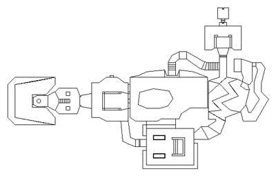
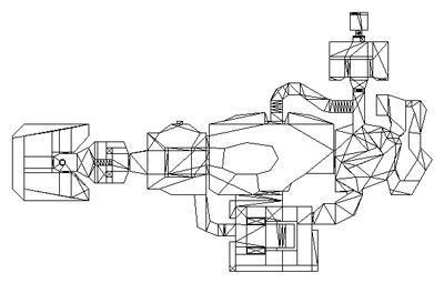
The level I've been working with as a test for the TI-83+ 3D engine was something I quickly threw together. I've never been much good at the design side of things, and my lack of imagination was producing something very simple that wasn't really challenging the engine and testing whether it could be used in a game. Looking for inspiration, I played through map E2M7 in DOOM and found a fairly interesting room to try to convert.
I'm sure you can tell which is the original room from DOOM and which is my adaptation of it.
Since the last post I have had to make quite a few tweaks to the engine. In the previous build there was a bug which cropped up when the top or bottom edges of walls appeared above or below the screen bounds. This turned out to be caused by a routine that was intended to clip a signed 16-bit integer to the range 0-63; it would return 0 for values 128 to 255 instead of 63. Fortunately this was an easy fix.
Another bug was in the way "upper and lower" walls were handled. Sectors have different heights and "upper and lower" walls go between two adjacent sectors and connect the ceiling of one to the other and the floor of one to the other, leaving a gap in the middle.
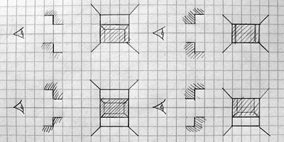
The above picture shows the four main types of sector-to-sector transition through an "upper and lower" wall type. Different transitions require different numbers of horizontal wall edges to be traced; in the bottom left example (going to a sector that has a lower ceiling and higher floor than the current one) four lines would be required and in the top right example (going to a sector that has a higher ceiling and lower floor than the current one) two lines would be required. The previous version of the engine always drew four lines, which would produce a spurious line above or below the "hole" for three out of the four different combinations of sector-to-sector transition. By comparing sector heights the right number of horizontal lines can be drawn, which greatly improves the appearance of the world and slightly increases the performance, too.
A less immediately obvious limitation was in my implementation of the BSP tree structure. Each node on the tree splits the world geometry into two halves; one half is in "front" of the partition and the other is "behind" it. Each chunk of split geometry can be further subdivided by additional partitions until you're left with a collection of walls that surround a convex region. You can then walk the tree, checking which side of each partition you are on to determine the order that the walls should be rendered in. For more detailed information the Wikipedia article on binary space partitioning is a good starting place but the basic requirement is that you should be able to slice up level geometry into convex regions with partitions. I had naïvely assumed that horizontal or vertical partitions would be sufficient (and they are useful as you can very quickly determine which side of a horizontal or vertical line the camera is on). However, this room demonstrated that such a limitation would not be practical.
Consider the above geometry. The black lines are walls and the small grey lines represent the wall normals; that is, the walls face the inside of the "Z". The wall in the middle is double-sided; you could put the camera above or below it and see it. However you slice that map up with horizontal or vertical partitions you will still end up with regions that are not convex.
A single partition along the central wall divides the map into two convex regions. I had initially thought that checking which side of such a partition the camera lay would be an expensive operation, but it's not too bad; as a line can be represented by the expression y=mx+c I can store the gradient m and y-intercept c in the level data and simply plug in the camera's x and compare to y to determine the side. A single multiplication and an addition isn't too much to ask for.
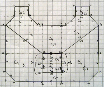
Fortunately, there are only two of these partitions in the level!
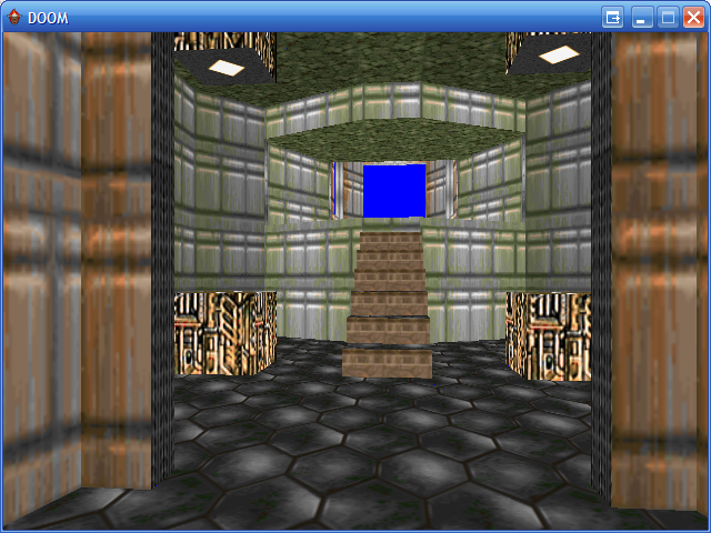
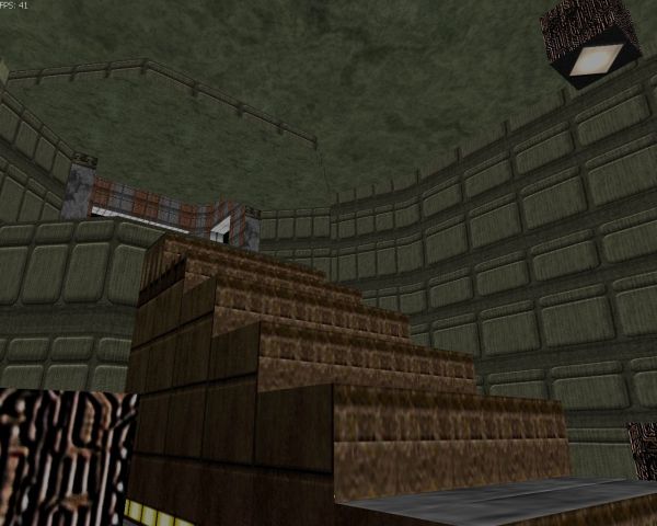
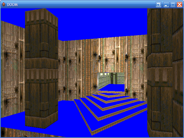
I have added some other features to the demo program. Pressing Zoom when using a calculator that can run at 15MHz (a TI-83+ SE or any TI-84+) toggles the speed between 6MHz and 15MHz. Pressing Mode or X,T,Θ,n allows you to look up or down. Pressing Window toggles between the default free movement and a mode which snaps you to a fixed height above the floor. These additions are shown in the below screenshot (click to view the animation):
Unfortunately, performance is lousy. Viewing the stairs drops the framerate to a rather sluggish 6 FPS when running at 6MHz (most of the above screenshot is recorded at 15MHz). The LCD's natural motion blur helps a little (it feels a lot more fluid on the calculator than it does on a PC emulator) but I'm aiming for a minimum of 10 FPS, so I need to make quite a few optimisations. There are several low-level ones that could be made; for example, when clipping the 2D line segments to the display I'm using a generic line clipper that clips the line both horizontally and vertically. As wall has been clipped to the horizontal field of view by that point I only really need to clip it to the top and bottom edges of the display. There are also some high-level optimisations to be made; for example, double-sided walls are currently stored as two distinct walls with the vertex order swapped. This means that to handle both sides of the wall the engine has to clip and project it twice, which involves lots of expensive divisions and multiplications. The results of these operations could be cached so that they only needed to be calculated once.
A TI-83 and TI-83+ binary is available if you'd like to try the demonstration on your calculator: please download Nostromo.zip. The usual disclaimers about backing up your data before running the program apply!
XNA DOOM3
Thursday, 3rd July 2008
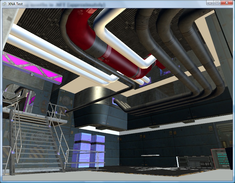
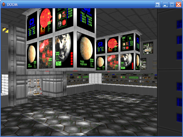
This journal is starting to look a little drab, so here's a splash of colour.
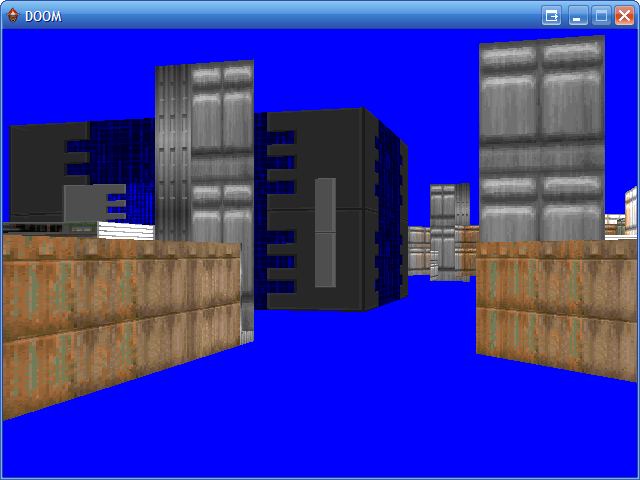
Not really all that colourful, on second thoughts.  I fancied a short break from BBC BASIC, and seeing that the current XNA CTP supports VS 2008 I thought I'd try a bit more work on hardware-accelerated 3D. I've never worked with shadows, bump mapping or visibility portals, and have a copy of DOOM 3, so thought that would provide a nice set of resources to experiment with.

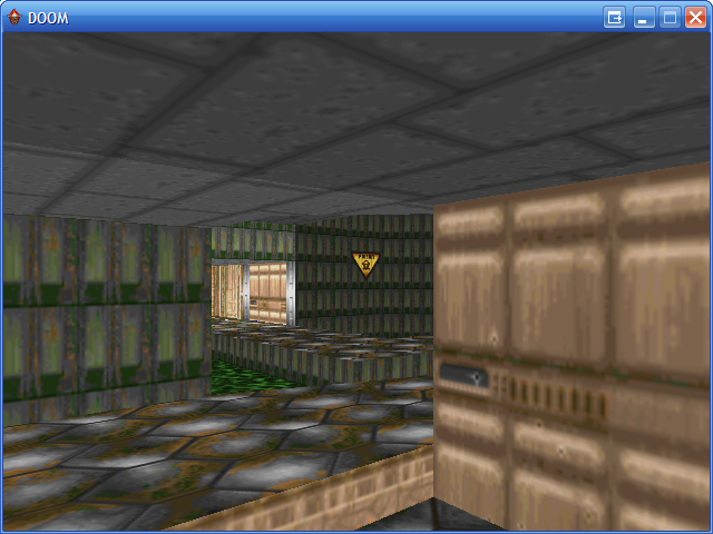
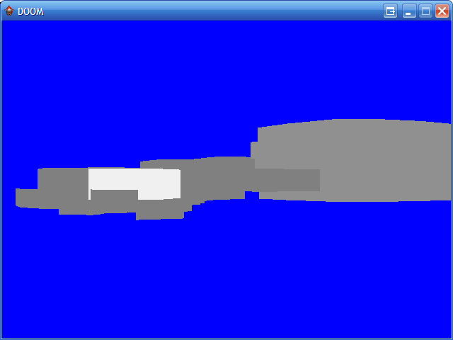
The screenshots are generated by simply brute-force rendering of all surfaces of all models in a level (.proc) file. The odd colours and lighting are courtesy of the default lighting provided by the BasicEffect class. The level files are simple to parse (they're just text files breaking each surface down into vertex and index arrays, ready to be fed to the video hardware), so though I've not found much documentation on them it's been pretty easy to guess what's what so far.
The above textures are loaded by taking the material name and appending .tga, which seems to return a random mixture of specular, diffuse or normal maps. There is a materials directory that appears to contain definitions for which image file to use for each different type of texture map, so that looks like the next thing to investigate.
DOOM Source
Thursday, 20th April 2006
You can download the source to the DOOM project below here.
It's a real mess in places, mainly in the way it loads level geometry. DirectX initialisation is hard-coded with no fallback code if some feature is missing or unsupported.
Usage: DOOM <iwad> <level>
eg:
DOOM DOOM2.WAD MAP31
DOOM DOOM.WAD E1M3
DOOM TNT.WAD MAP03
Keys: use the cursor keys to move around, A and Z to move up and down.
Broken:
- Floor splitting is abysmal. It is highly inefficient and occasionally wrong. The floor splitting code breaks sectors into horizontal spans which it then splits into triangles - uneven vertex placement results in largish cracks between sectors or "hairline" dancing-pixel cracks inside sectors. Large holes are usually the case of a sector that "overflows" another one. Ideally; decode floors via ssector/seg information or just use glBSP.
- Timing (level animation) is done via the primitive Timer class. If something starts to hog CPU time, the timers all slow down leading to inconsistent animation speeds.
- Scrolling walls and light effects are controlled differently; sector light effects (which affect a large amount of geometry) save the vertex array written to the vertex buffer away; this array is changed then sent to a vertex buffer, overwriting the existing data. The scrolling walls (affect a small amount of geometry) read the vertex buffer, alter the texture coordinates, then write it back. This results in a confict; if a linedef has both scrolling AND lighting effects, every time the light level changes the scroll offset is reset to the original linedef's value.
- Skies that occlude geometry that is visible normally aren't handled correctly.
- Player start angle is occasionally backwards.
- Some of the more bizarre walls still don't display properly.
Lights, camera - action!
Wednesday, 22nd March 2006
I've also added a MUS lump (music format used by DOOM) player, using the MIDI message functions in winmm. The only feature left unsupported is the pitch wheel, as I can't quite work out the MIDI command for it.
If somebody could please explain the logic behind MUS, please tell me. It's essentially the same as MIDI, except each command has a different byte (so you have to convert to the correct byte first), uses channel 15 for percussion (so you have to swap 15 with 9 and 9 with 15 - as 9 is the MIDI percussion channel) and uses a controller for a patch change, whereas MIDI has a specific patch change command rather than lumping it with the controllers.
Making the world live
Monday, 20th March 2006
It might have looked liked I'd got all the walls drawing and texturing correctly, some particular combinations were still wrong.
Some walls looked completely wrong until you got up close, and with a flickering burst of z-fighting they'd resolve themselves. Or rather, fuzzy patches would resolve themselves.
This would not do!
Here's a good (or bad) example of where things were going wrong:

Something tells me I shouldn't hire the UAC's architect. The problem, it turns out, is the way connected sectors handle which coordinates to use for upper, middle and lower sections.
I was using the current sector's ceiling and floor height as the midsection, and the areas between the two sectors' ceilings or floors as the upper and lower coordinates.
The problem is if the current sector is taller than the adjacent sector. This makes the "middle" section very tall, and the upper and lower sections end up folding back down on themselves - like this:
I tried all combinations of ordering, none of which worked - either rendering that area correctly and removing old healthy walls; or displaying correctly but with texture coordinates awry. The solution in the end was very simple - sort the four height levels into TopCeiling, MidCeiling, MidFloor, and LowFloor.
Two things in that image are wrong. Most noticably - no alpha blending on the walls. You should be able to see through that grille. The second is that in the real DOOM, you can see under the grille itself.
The latter is quite easy to fix; looking in my WAD spec guide, I see:There are some transparent textures which can be used as middle textures on 2-sided sidedefs (between sectors). These textures need to be composed of a single patch (see [8-4]), and note that on a very tall wall, they will NOT be tiled. Only one will be placed, at the spot determined by the "lower unpegged" flag being on/off and the sidedef's y offset. And if a transparent texture is used as an upper or lower texture, then the good old "Tutti Frutti" effect will have its way.
In short; if the ceiling_height - floor_height > texture_height then floor_height = ceiling_height - texture_height (the Z axis, floor height, points "upwards", so ceilings have a greater Z coordinate than floors).
As for transparency, my aim to keeping this simple prevailed. Rather than sort the walls from back to front manually, I isolate the vertex buffers relating to textures with transparent areas and draw them after all the other walls. This would still lead to problems where looking through one transparent wall at another would leave holes in the far wall if it had been drawn afterwards, so I draw all the walls twice - the first time with z-writes disabled, the second with them reenabled.
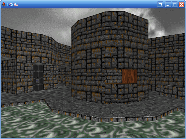
The entry room from E1M3 with alpha blending and fixed wall coordinates looks like this, now:
I bought the collector's edition of DOOM for this project (it's quite cheap) and picked it up over the weekend. Mostly because it had Final DOOM on it (I only had Ultimate DOOM and DOOM II), but also because it claimed to run on Windows XP. It didn't even list DOS as a supported platform.
I was surprised to find that it's just DOOM95, which quite simply doesn't work on Windows XP. Neither does it work on 2000. The mouse doesn't work, and the colours are all wrong. Using XP's compatibility mode and 256 colour mode seems to cure it for a few minutes before it goes all weird again. (I don't know if it's entirely graphics-card related, as DOOM95 ran fine under Windows 95 on my old PC - then went funky colours after upgrading to 2000).
There is a relevance to this - loading the Plutonium WAD file slowed my PC right down for about 3 minutes - though the CPU usage was extremely low. The reason? A slight memory hogging issue...
Turns out it was trying to decode some extra files that had appeared in the WAD file as images, with dimensions of 10,000 by 10,000 or greater. No wonder it was consuming memory at such a rate!
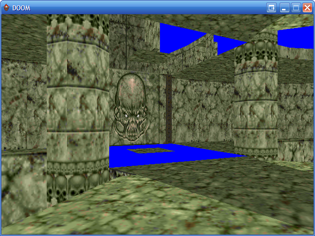
Loading the Plutonia WAD also showed this error:
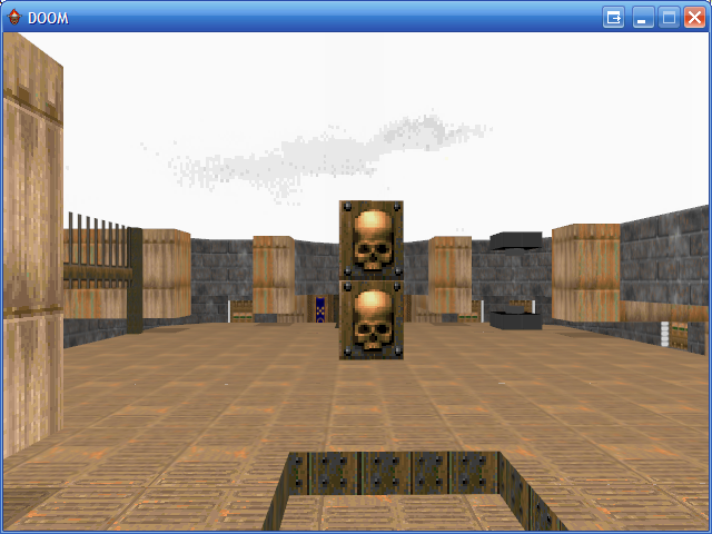
The pillar isn't really meant to be a pillar - in reality, only the top skull is meant to display. This sounds a bit like a middle section not tiling glitch - and looking at the lines that make up the skull, each is marked as double sided. Double sided lines are generally used for transparent wall sections - so rather than check the transparency of a wall section, I check to see if it's double sided or not.
Much better!
Two things that made the DOOM environment come to life - excluding, of course, actually coming to life and moving around - were the changes in sector lighting and animated textures on floors and walls.
Adjusting the light level of sectors - blinking or pulsating lights, for example - would require quite a lot of code. On the other hand, all the animated textures need is a bit of extra code on the WAD parser to work out which textures come between the animated texture markers and a bit of extra code on the renderer to swap texture indices around every ~300ms.
Well, that's the easy bit done. Interesting to note, however, that Doomsday (jDoom) - or at least my copy of it - does not handle animated textures correctly. A particular set of textures used in Final DOOM - the spinning tape drives on computers - appear static in jDoom, or only use the first few frames.
Currently, the level's geometry is split up by texture - so I cycle through each different texture, setting it as current, then sending all the geometry that uses that texture (as a vertex buffer) to be drawn. Better control over sectors would mean that I should split by texture, then by sector.
Unfortunately, my attempt resulted in a, uh, slight performance hit. By slight, I mean from ~370FPS on my Radeon 9550 to ~4FPS. Whoops!
It turns out that I was accidentally repeating each sector - even with that fixed, I was still at about 50FPS.
It would probably be simpler - not to mention faster - to order the vertices in sector order, but to record the offset and length inside the vertex buffer for each sector so that should I need to change it I could very easily lock and update it. To put it more clearly, I should maintain a list, for each sector, recording which vertex buffers form part of it and the offset and length (in bytes) to the vertices specific to that sector. That way I can easily (not to mention quickly) tweak the vertices to my heart's content - be it adjusting their Color property to flicker lights, or their heights to open and close doors.

No more holes.
Friday, 17th March 2006
With the exception of some very bizarrely shaped sectors, I've patched up the holes by making the floor splitter a bit more intelligent. It also removes some redundancies.
The more exotic levels generate about 5000 triangles, which is fairly reasonable.
Now I need to do battle with the physically impossible levels DOOM creates...
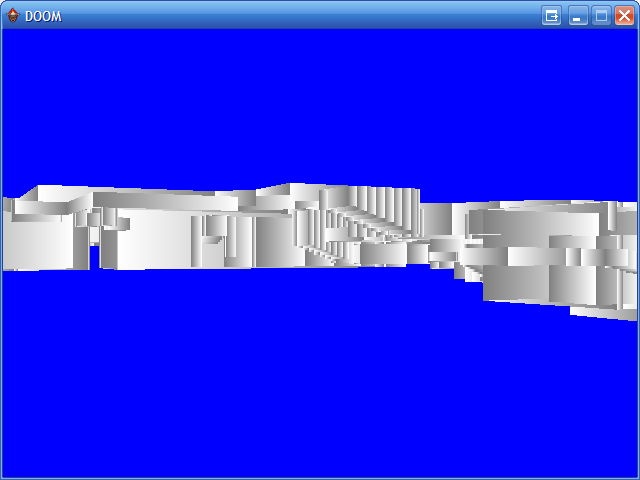
In DOOM, skies and floors are actually marked as the special texture SKY_1. However, rather than drawing it using the normal mapping, it's drawn fixed to the background.
I'm currently just drawing a sky cylinder, and not drawing ceilings where the sky texture would normally be. I need to find some way of masking out the buildings that shouldn't be visible.
World's Worst Sector Splitter
Thursday, 16th March 2006
As with many programming problems, a potential solution presents itself at about 2AM when you suddenly awake and hunt paper and pencil before the brilliant idea vanishes into the groggy murk that is forgetfulness.
In this instance, a solution did present itself, but it's far from 'brilliant'.
I was pondering DOOM's floors, and how to split them up. I came up with a simple, optimal solution - optimal, provided that the sector I was splitting into triangles was a rectangle with sides perfectly aligned the the (x,y) axes. Happily, DOOM follows that pattern fairly often.
Here we have the typical sector. It's sector number one from E1M1, the ground that surrounds the acid pool outside the window. As you can see, it's not entirely convex, and has a hole in the middle. I have access to the lines and points that surround the sector.
My technique runs like this:
- Split the sector up into horizontal spans. To do this, I cycle through every single line in the sector, and for every different Y coordinate I split the sector.
- For each individual span, go through each line in the sector. If it's completely outside the span, discard it. If it's partially outside (no line will ever have a point half-way inside the span), clip it to the upper/lower Y bounds.
- Sort these lines from left to right, then group into pairs. Each pair, when combined with the top and bottom Y boundary, forms a trapezium. Split this into two triangles - there's a part of your floor.
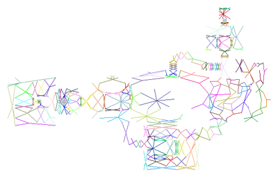
This method is fairly simple, and appears to work pretty well:
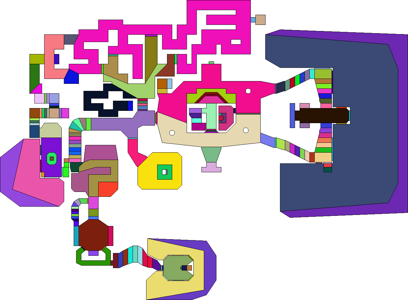
Note the large magenta shape at the top (maze in E1M2). That's a single sector!
The image is less pretty if I dump out an image showing the triangles generated:

Hopefully that makes my method slightly clearer.
For some areas, it does pretty well. In others (sectors not perfectly aligned to the (x,y) axes) it generates an absolutely horrible mess of triangles.
Grouping walls by texture and generating a new vertex buffer for each texture group worked pretty well, so I've done the same for floors.
The first floor test looked pretty good (minus texture coordinates):
...so I fixed it up a bit, and flipped the vertex order to support ceilings as well.
One problem I had been worried about had reared it's ugly head, however - hairline cracks between triangles, showing the lovely bright blue through the dark and dismal UAC facility. It was trivial to fix, however; replace the floating-point linear interpolation (to clip lines to the single horizontal span in the floor splitting code) with the integer-based method. This got rid of all the rounding errors, and the cracks were gone.
The floor splitting code might inefficient, but it is simple - even then, however, it does fail on certain segments resulting in slightly-larger-than-hairline cracks on certain levels.
I'm not quite sure why that's happening. I have a hunch that in certain cases there is an extra line when breaking up sectors into horizontal spans and you end up with an odd number of dividing lines. In some cases, this extra line is at the end - and it is ignored safely. If it's at the beginning, though, everything is shunted along one and the whole sector span is drawn incorrectly.
Also, (and this can be verifed), some sector floors/ceilings end up being drawn back-to-front, and fall prey to the backface culling. Ducking below the surface of the floor, you can clearly see the missing floor deciding to be a ceiling.
One potential improvement would be to split the floor twice - once in horizontal spans, once in vertical spans - and use the one that produces the least triangles.
The texturing issues from last post were fixed with a variety of code changes - some sector-to-sector wall segments were being drawn upside down (the code now flips the heights around so they're in the correct order); the light level of a sector's wall is calculated by the brightest between it and any adjacent sector; lower texture pegging fixed to align correctly.
Managed DirectX is awesome
Monday, 13th March 2006
A few years back I had a go with DirectX 8, helped along by the excellent DirectX4VB website and tutorials.
The best thing I cranked out was a simple DOOM-ish 3D engine, minus sprites (just walls and floors).
(All images are click-for-big).
I fancied another go, this time not in VB6 but in C# and not with DirectX 8 but Managed DirectX 9.
I had an old copy of the SDK so got the obligatory spinning coloured untextured triangle going, then hunted for a proper project to learn with.
Keeping with the theme of last time's venture, I decided to go back to DOOM, but not DOOM-ish - I'd load the levels and graphics from an original DOOM WAD file. There's something oddly satisfying about pressing F5 and watch a familiar 3D world spring into view
I'd written a very simple VB.NET WAD resource viewer, so rewrote the various graphics functions in C# and dug out a hex editor to work out what goes on inside DOOM.
Each level has a similar bunch of data lumps ("lump" is the name of a single resource within the WAD); THINGS that define the location of objects inside the map, NODES for the BSP tree, VERTEXES for the vertices that make up a level and so on.
One problem with DOOM is that there is no "vectorised" floor. The walls are easy enough; by studying the LINEDEF/SIDEDEF/SECTOR lumps you can work out the VERTEXES you need to use to build up a single wall. Floors are filled in after the walls are drawn; to be able to draw a floor on 3D hardware I'd need to split down the sectors into triangles manually. For the moment I shall concentrate on walls.
A quick bit of coding later; drawing by splitting each wall into a small vertex buffer (two triangles) then drawing (one end of the wall is white, the other grey) gives me this:
Something's working... but something isn't, as well. Moving around looks odd, and no wonder; no Z-buffering!
Switching on Z-buffering and colouring each wall based on the light level of the sector gives me these rather better results:

One thing that I've never been aware of when it comes to 3D graphics are the best practices for how I send data to the graphics card. For this, I've grouped every single wall by texture. I've loaded all the textures I'll need for the walls into an array, then built up a vertex buffer for each texture's walls. When I render, I cycle through each texture, setting it as active then drawing that texture's vertex buffer. It appears to be fast enough, but then again DOOM with it's ~2000 poly levels isn't demanding much!
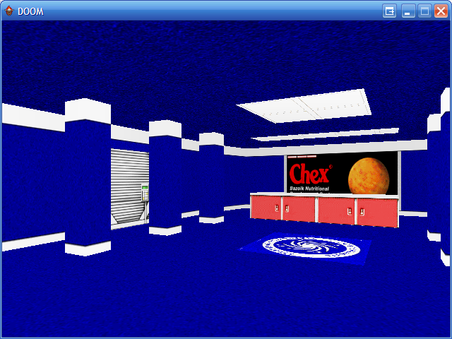
Texture mapping adds a lot of detail to the world... so:
The textures appear a bit odd as they're being simply stretched to fill the entire wall they're put on rather than tile neatly as DOOM intended. That's an easy enough fix:
There are still some texturing glitches, most noticeably on walls where the lower texture (the texture that spans the gap between the floors of two sectors of different heights) where they are marked as "unpegged":
I can't quite work out how the texturing is meant to go there... so I've left it for the moment, and had a bash at floors.
It appears that a combination of subsectors (SSECTORS) and segments (SEGS) can be used to represent convex polygons that make up sectors. I added a bit of code to the level loader that rips out the subsector and segment information - it produced these images:
Subsectors
Segments
This doesn't look too promising; if you look at the central part (where the green acid pool is -- this is E1M1) you can see there's a rather large area with no segments in it at all. I added a simple bit of code that broke up the segments into fans; here's the result:
The hole is very noticable in that image. Quite a few of the segments are made up of single lines (just two points), which leads me to believe that I'm thinking that they're something they're not.
For the moment DOOM has to go without floors.
Subscribe to an RSS feed that only contains items with the DOOM tag.