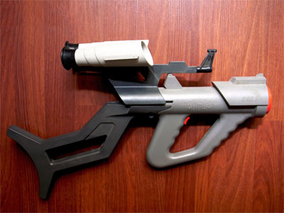
Light Gun Commando: LCD-compatible light gun support for original console hardware?
Tuesday, 13th December 2022
As the previous entries on this site might indicate, I do enjoy a good light gun game. Unfortunately, when it comes to playing them on home consoles you usually need to use a CRT television for the gun controllers to work. I have a CRT or two at my disposal but I'm well aware they won't last forever and they're not really the most convenient devices even when they are working at their best.
Bearing this in mind I decided to try to find a way to get light guns working on LCD TVs. My experiments back in early 2015 – called DC-LiGuE, the "Dreamcast Light Gun Emulator" – never amounted to much. I was able to build a circuit that I could feed coordinates into and translate that into light gun inputs without involving a CRT display, but I had a couple of major issues. The first was that I was unable to talk to the Dreamcast directly; its controller protocol is much too fast to decode reliably using the ATmega microcontrollers I favour in my projects, so my interface involved shining a bright white LED into the end of a regular Dreamcast light gun. The second issue was disappointment in the Wii remote I was hoping to use as the light gun input; I'd tried some homebrew programs that translated the data from its IR tracking camera into pointer events as well as the Mayflash DolphinBar (which shows up as a regular USB mouse on a PC) and the accuracy was generally pretty poor and not subsitute for a light gun.
More recently I was made aware of other IR-based light gun solutions such as GUN4IR from Boojakascha's YouTube video on the project. I thought I should give the Wii remote another chance! I'd also realised that Mayflash's DolphinBar has a fourth mode intended for use with the Dolphin emulator in which it presents the four paired Wii remotes as four USB HID devices. This makes experimenting with the Wii remote very easy, as you don't need to worry about any of the Bluetooth pairing side of things. I stuck some IR LEDs around my monitor in the GUN4IR configuration and knocked together a quick prototype in C# that analysed the tracked points and translated them into pointer coordinates. Having the four LEDs around the monitor (instead of just two in the Wii sensor bar) makes the aim tracking much easier and much more accurate.
Skipping ahead in the story a bit, the video below shows the C# prototype running in the monitor on the left. The diamond shape is drawn around the four tracked IR emitter points. If the Wii remote is aimed far enough away from the centre of the screen it may lose sight of one or more of these points, but the software does a reasonable job of reconstructing the diamond based on the remaining points it can see. The large bright white dot is the calculated pointer position.
ACTION! Playing PS2 Time Crisis II on an LCD with a Wii remote. At the moment my PC sits in the middle to handle Bluetooth and aim tracking before sending data to a circuit pretending to be a Guncon, so next step would be to replace that with a Bluetooth-enabled microcontroller. pic.twitter.com/GA26q1utgz
— Ben Ryves (@benryves) November 18, 2022
In example the Wii remote is being used to play Time Crisis II on the PlayStation 2. This is a happening on a real PS2, not an emulator on the PC. To achieve this a circuit that mimics a Guncon light gun is connected between my PC and the PS2, and the PC sends button and pointer data to this circuit. Different circuits could be built that could mimic different light guns for different consoles, providing a somewhat universal light gun solution. One issue is that my PC isn't anywhere near my consoles, though, and not everyone is going to have a DolphinBar so replacing the PC side with a dedicated unit seemed like a good idea.
If I was going to use Wii remotes then I'd need something that could speak Bluetooth. The ESP32 microcontroller is cheap and provides a system-on-a-chip with Bluetooth (and a corresponding software stack) that seemed somewhat easy to get into. There was a simple Bluetooth HID host demo that served as a good starting point, and once I'd got the Wii remote paired with the ESP32 and transferring HID reports I translated the C# prototype code I'd written into C and got the ESP32 talking to the simulated Guncon instead of my PC.
Moved all the aim tracking code to the ESP32 so no PC is required. Holding the A button on the Wii remote to pop out of cover was getting tiring so made it automatically hold A if the camera can see any IR lights, allowing me to reload by pointing off-screen. pic.twitter.com/iEn3TS9vAX
— Ben Ryves (@benryves) November 22, 2022
The choice of the PlayStation Guncon was deliberate, as simulating this sort of light gun if you know the pointer coordinates you wish to send is very easy. The Guncon is quite unusual compared to other light guns of the era in that it handles the position calculation within the gun itself and then transfers the coordinates directly to the console over the standard controller protocol used to normally send button statuses or analogue joystick positions. Most other light guns just send a pulse on a dedicated "light gun" input pin when they see flashes of light from the CRT's raster scanning pattern and rely on the console to handle the position calculation, which the console can do as it can ask the video chip which part of the frame it was sending to the TV at the moment the light gun saw the light and from that determine where the gun was aimed. For the Guncon to be able to do this without direct access to the video chip it needs to have access to the generated video signal, which is why the Guncon has an RCA connector on it to pass the console's video signal through it. To be able to make most other light guns work, I'd need to generate the pulses seen when the Wii remote is pointing at the part of the screen that the console is currently outputting, and to do that I'd need to be syncronised with the console's video output.
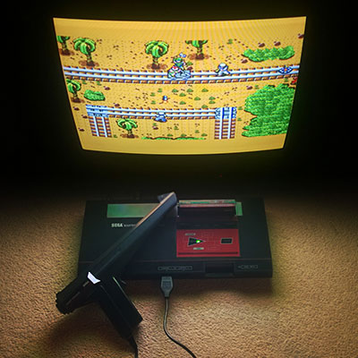
Fortunately the ESP32 has a motor PWM controller that can be synchronised to external sources and so by adding an LM1881 sync separator circuit to extract the composite (horizontal) and vertical sync pulses to give it something to synchronise itself to I was able to generate pulses that looked like they might have come from a light gun based on the point on the screen the Wii remote was aimed at. I first tested this with the Master System, pretending to be a Light Phaser, before feeding the signals into a circuit that pretends to be a Mega Drive Justifier.
Imitating a Guncon is easy as it reports coordinates to the console, most other light guns send timed pulses when their sensor detects light. My Wiimote adaptor now simulates this light sensor output, synced to the video, and can now hit the broadside of a barn on a Mega-CD. pic.twitter.com/TlsLx9VVo1
— Ben Ryves (@benryves) November 24, 2022
The point I'm aiming for with all of this is to have a central unit sitting under my TV that has the Wii remotes paired to it and the video signal passing through it. It will then have a socket on the front that can be connected to the console-specific light gun simulating cables which will then be plugged into their corresponding consoles. One system that can hopefully cover all the possible combination of light guns on original hardware. When I think of being prepared for any eventuality with a large collection of guns I naturally think of the classic Arnold Schwarzenegger film Commando, and so I've decided to call this project the Light Gun Commando.
Unlike John Matrix, however, I prefer to go into battle with a friend and so it's very important to me that not only does this system cover as many light gun types as possible, but also more than one player. I can't think of any console light gun games that support more than two simultaneous players so at the moment I'm concentrating on two player support but will probably leave space in protocol specifications for more. The following video shows a demonstration of two simultaneous guns in action:
Did any consoles support >2 simultaneous light guns? I've got two Wii remotes working together now, here simulating two Hyper Blaster/Justifier guns plugged into a PlayStation. pic.twitter.com/My8glK4lny
— Ben Ryves (@benryves) December 4, 2022
In the video we're back to the PlayStation, but now simulating a Hyper Blaster instead of a Guncon. This is using the same circuit as the Guncon adaptor, but the firmware now supports different gun modes. Before the main host device sends any data to a console-specific gun adaptor it asks it to describe its capabilities. The adaptor replies with a block of formatted data describing each gun it can simulate; this includes a list of all buttons it has (including a descriptive name and a generic button type such as "trigger button", "start button" or "back button") and any axes it has (such as the pointer X and Y for the Guncon). These gun descriptions can then be repeated for multiple players if an adaptor can simulate more than one gun at a time, and then these player/gun descriptions can be grouped into different modes (e.g. "Two Guncons", "Two Hyper Blasters"). Pressing a button on the host device can then cycle between the different gun modes. The host device can use these mode, player and gun descriptions to construct status reports based on the current state of the Wii remotes, and by using generic button types (e.g. "trigger button" or "start button") the Wii buttons can be mapped automatically to suitable simulated gun buttons.
This automatic mapping is not just a matter of convenience, but is also intended to keep the host device and simulated guns separated. The simulated guns only need to worry about the guns they are simulating and not about button mapping from a Wii remote specifically. This is to allow the host device to be replaced by other hosts but still be able to use the same console-specific adaptors; the idea is that a GUN4IR or Sinden light gun host could be put together in the same way that I'm putting together a Wii remote host, and as long as the communication protocol between them is sensibly designed this should be a pretty straightforward endeavour.
To this end I'm currently trying to hack together as many different simulated light guns as I can to ensure that the communication protocol works well for them all. I've already mentioned the Sega Master System's Light Phaser, Mega Drive's Justifier and PlayStation's Guncon and Hyper Blaster. I did also get the Saturn's Virtua Gun working:
The first home light gun game I played was Virtua Cop on the Sega Saturn, and I remember being amazed by the technical wizardry of the Virtua Gun. Time to take a trip back to Virtua City, this time with a Wii remote in my hand... pic.twitter.com/o4IgxWfprd
— Ben Ryves (@benryves) December 6, 2022
This all started back in 2015 with an attempt to mimic the Dreamcast's Light Gun, though, so if it's nearly eight years later and still no closer to that goal it's surely a bit disappointing? The main problem I had with the Dreamcast is that its controller bus uses a wire protocol that's not directly compatible with any existing standard that might be built into a microcontroller (the PlayStation uses a minor variation of SPI, for example) and is too fast to decode reliably in software on the microcontrollers I typically use. I have seen projects that perform clever tricks to work around this, such as dumping the bus state to RAM in a tight loop before decoding it (slowly) afterwards but these never seemed particularly robust and I didn't want to risk dropping data coming in from the host via the serial port if I was busy spending all available CPU time on speaking to the Dreamcast.
My solution was to look into the dsPIC33, specifically a model capable of running at 140MHz (up to 70 MIPS) which has sufficient grunt to decode the controller protocol in software with cycles to spare, enough RAM to store large data frames and DMA capabilities to be able to keep receiving data from the host device with zero CPU overhead if we're otherwise busy talking to the Dreamcast – all in in a hobbyist-friendly breadboardable DIP28 package!
"...the DEAD!"
— Ben Ryves (@benryves) December 11, 2022
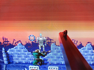
The House of the Dead 2 is my favourite light gun game, so even if it had a native Wii conversion it seemed like the ideal choice to test my Wii remote->Dreamcast light gun adaptor. Need to fine-tune timings and add 31kHz/VGA support but quick lash-up plays OK. pic.twitter.com/0aUzL4v4BV
As the video above hopefully demonstrates, the dsPIC33 seems to have done the trick and I can join the dogs of the AMS and hopefully not suffer like G did.
There's quite a lot work to go but I'm already feeling slightly less worried that if my CRT TVs all conk out I'll be stranded with no way to play my light gun games.
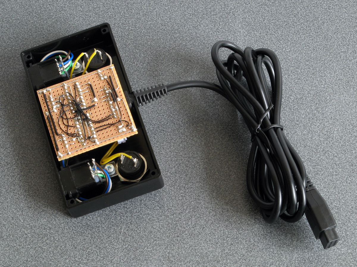
The completed Light Phaser to Justifier adaptor
Wednesday, 29th April 2020
Since my previous post I've had a chance to test the Sega Light Phaser to Konami Justifier adaptor circuit with Lethal Enforcers II: Gun Fighters and it seems to work well throughout the game so I thought it was a good time to put the project into a neat box.
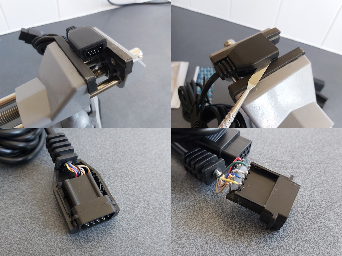
The Mega Drive uses common DE-9 connectors for its controller ports. You can easily find metal connectors with lugs for panel mounting however I wanted to use plastic connectors similar to the ones on the original console – not just for a consistent look, but to also protect the plastic connectors on the Sega Light Phasers from being scratched by the sharp edges of metal connectors. I'm using controller extension cables for the nice moulded connector and cable that plugs into the console, so thought I'd look at the controller socket end. Squeezing the bottom half of the connector splits the two halves apart and you can use a spudger or similar tool to pop the casing open and retrieve the connector – just what I needed!
I nearly always put my projects in off-the-shelf enclosures, cutting and drilling holes in them where required. In this project's case the most awkward holes to cut will be for the controller connectors as they do not have an external lip to mask any poorly-cut holes. As such, I thought I'd start here:

My process here is a bit tedious, but gets the job done – I cover the enclosure in masking tape, then mark out where the holes should appear. I use a drill to make several holes inside the shape I wish to cut out, then use a router bit or sharp knife to cut between the holes to open up the hole properly. A set of hand files is then used to bring the hole to its final shape and size, checking against the connector along the way to ensure an accurate fit.
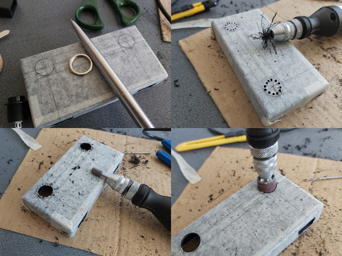
The circular holes for the buttons are cut in a similar fashion, except that as the buttons have outer lips that cover the borders of the hole the outer edges don't need to be quite as precise and a larger router bit and drum sander can speed up the job considerably rather than having to rely on careful hand filing.
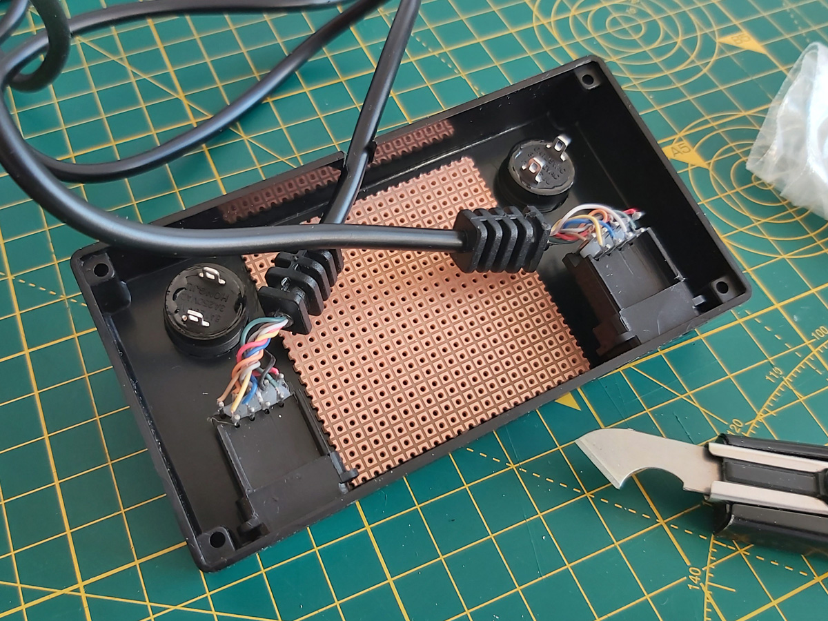
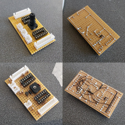
A rectangular notch was cut in the rear centre of the case for the cable to the console to exit through and the parts were then loosely installed for a test fit. A piece of pad board was cut to size by scoring it and snapping it over the edge of a table. I wanted it to be as large as possible to make it easier to fit all of the components and wires in, but could the case be closed with the cables and connectors in place too? To make sure it would I thought I'd start with the bulkiest of cables, the one that goes to the console.
I attached a nine-pin crimp connector to the end of the controller cable to plug into the pad board and experimented with the placement of the destination connector – I found that four rows down was about the closest it could go to the top edge of the board whilst still providing enough room for the cable coming in to bend neatly out of the way.
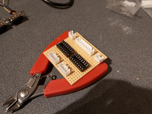
The various parts for the console output connector, light gun input connectors, start button connectors and multiplexer chip DIL sockets were placed on the pad board without soldering to get a rough idea of the final layout and component spacing, ensuring there was enough space around each part to install other components or wires. Once a rough idea was in mind, the main soldering work could begin!
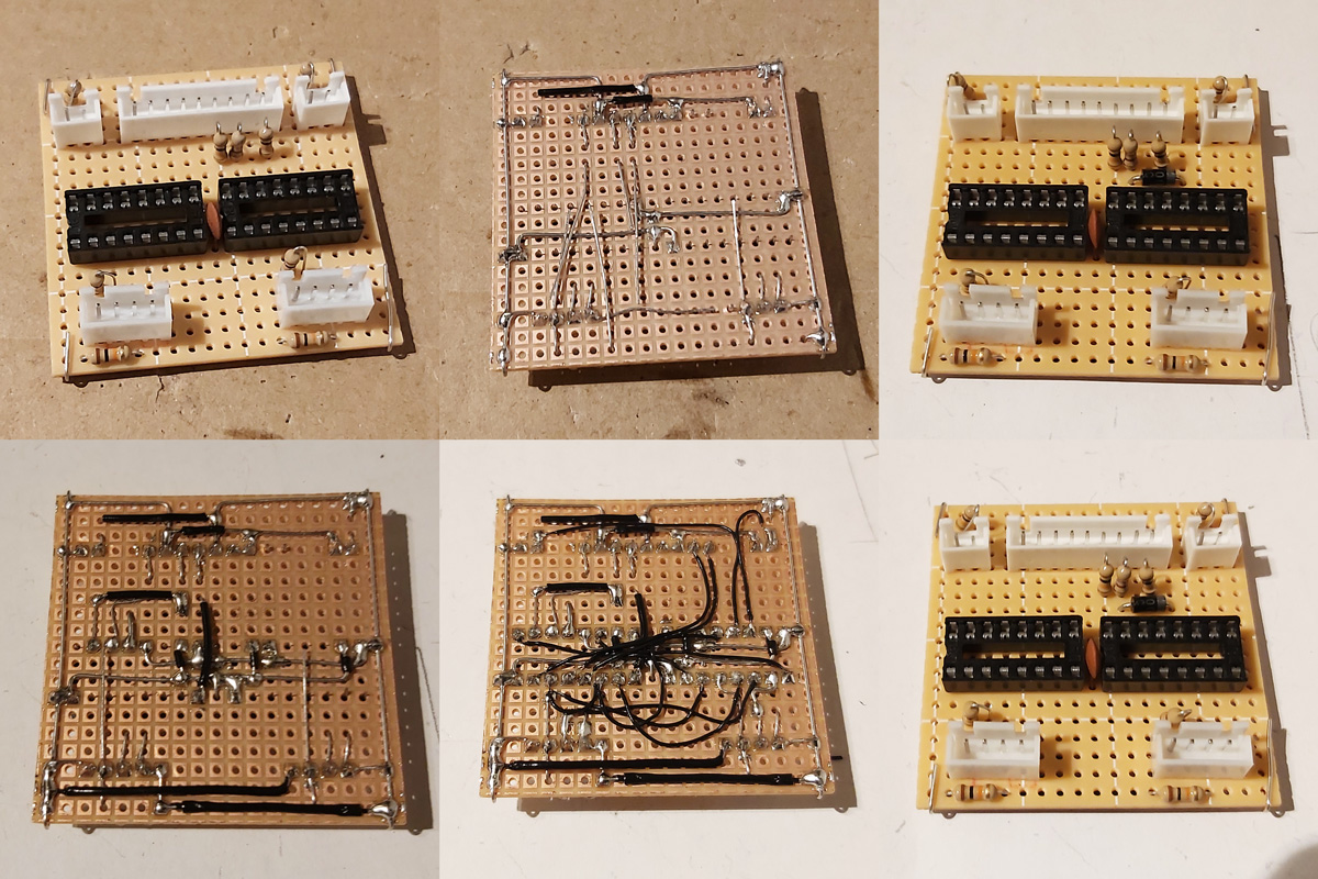
Not much appears to happen between the first and final stages, as most of the work takes place in the wiring on the bottom of the board. Connections that can be made in straight lines without crossing other connections are soldered first, followed by straight connections that cross other connections that can be insulated by slipping on a piece of insulation stripped from a reel of wire. When all of the easy connections are made in this way the outstanding connections are made by soldering lengths of thin wire wrap wire between points on the underside of the board. As each connection is made it is crossed off the circuit diagram – this allows me to check that the circuit diagram is correct, as if I can replicate the circuit from this diagram it's a pretty good indication that it's safe for other people to use to make their own versions of this project.
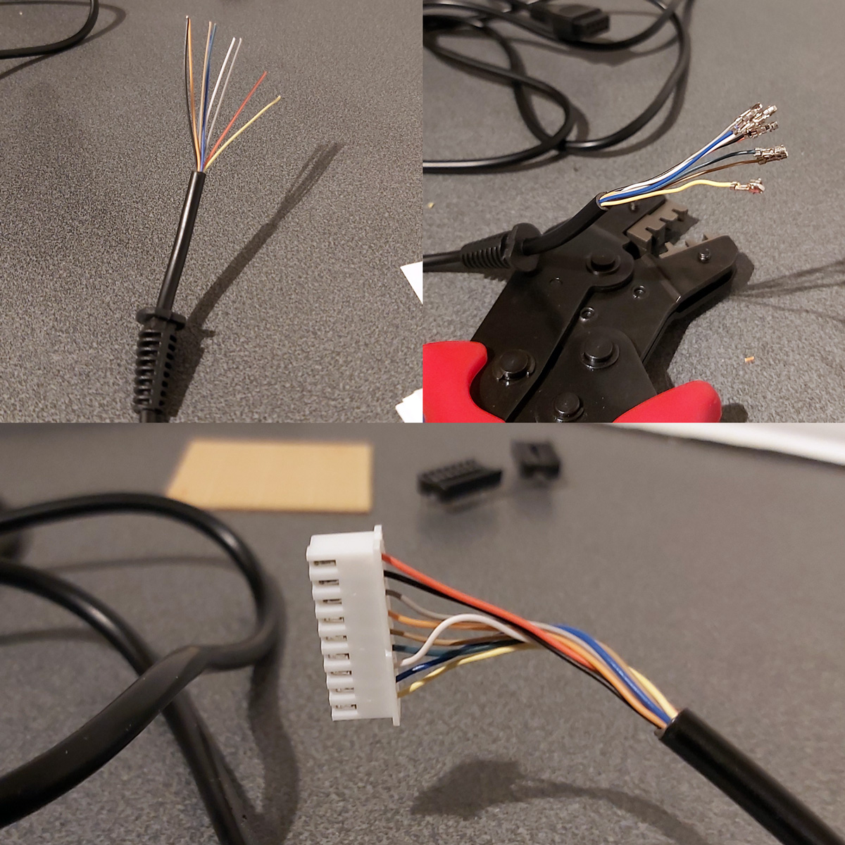
The DE-9 sockets used for the Light Phaser inputs have all nine pins soldered to the cable by default. We only care about four of them (VCC, GND, TL and TH) and as we don't have enough room for all nine connections to be soldered to the board four-pin connectors are used instead. The old wires are unsoldered and new wires and crimp connectors are attached in their place. This let me check that the circuit board was otherwise working fine, but I still need to figure out how to mount these connectors securely inside the enclosure. I was initially thinking of just holding them in place with hot glue, but this is not very elegant and makes future maintenance much harder! The DE-9 sockets do have a flat surface at the top that is only slightly more than 5mm from the top surface of the enclosure, and I do have some 5mm PCB standoffs that could be handy…
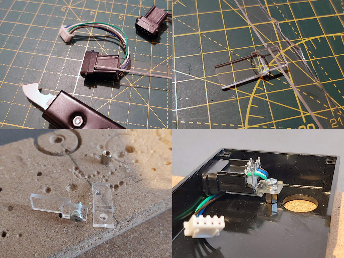
I cut a 9mm wide strip of acrylic from 2mm thick sheet which fits neatly into the top channel of the DE-9 connectors. I then cut it into short sections that could be glued together into Z-shaped brackets. The long section of the "Z" mounts to the DE-9 connector and the short section has a hole drilled through it so it can be secured to the PCB stand-off with a screw. The arrangement is then test fit inside the enclosure using double-sided sticky tape to check that a solid mount is possible – the screw to the PCB stand-off accounts for one part of that mount, and the tight fit of the connector inside the D-shaped hole in the enslosure accounts for the other part.
When it seems like a good fit is possible the Z-shaped brackets are glued to their DE-9 connectors. The DE-9 connectors are then installed in the enclosure with some glue on the bottom of the PCB stand-offs – when everything is lined up neatly this glue secures the stand-offs in the right position, albeit not very strongly.
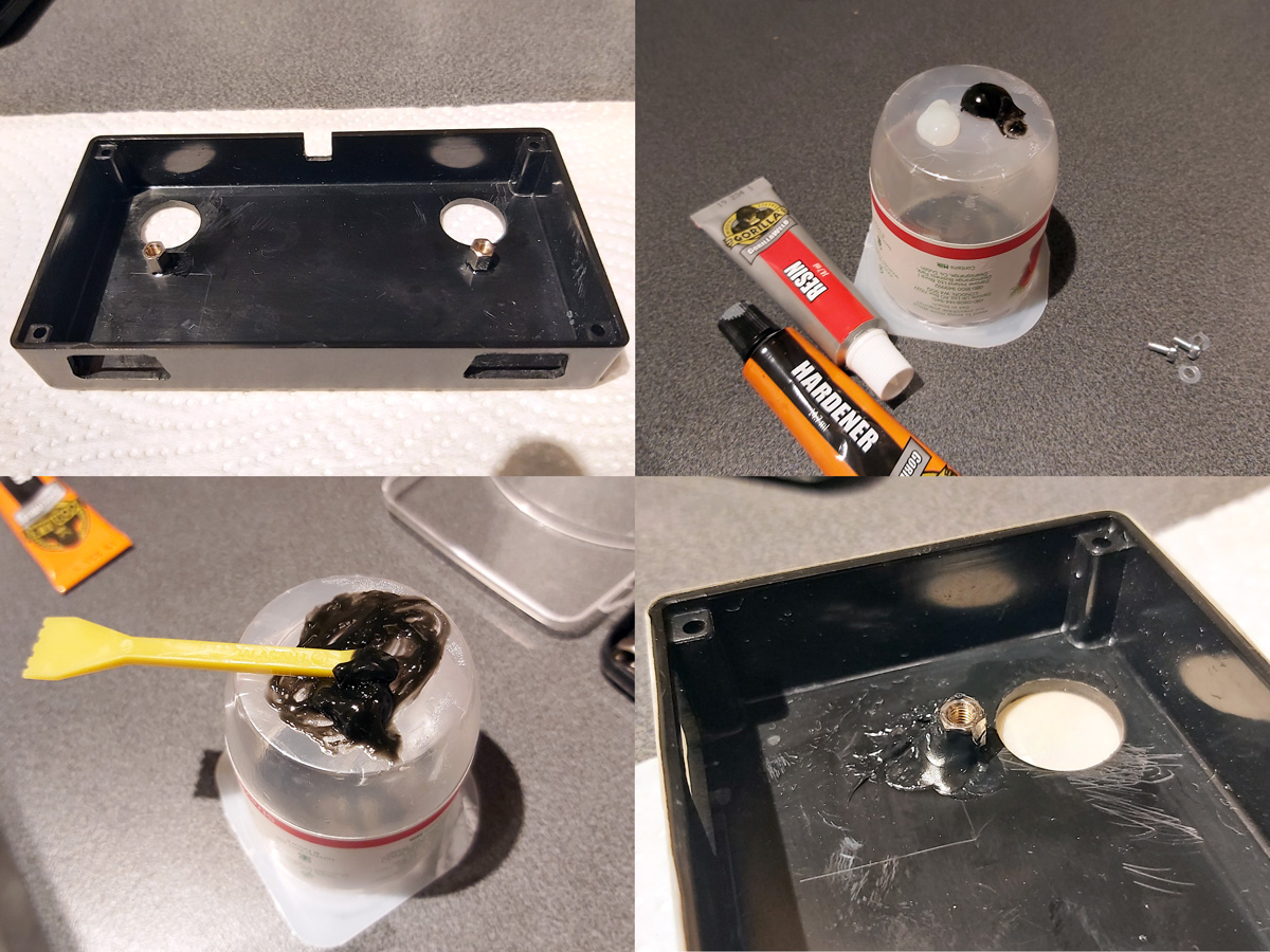
Once the glue had set the screws were removed and the DE-9 sockets were carefully removed. Two-part epoxy was then applied liberally around the PCB stand-offs to provide a bit of extra support. Unfortunately, the stand-offs are very close to the nuts used to secure the start buttons to the enclosure and as such not much epoxy could be placed on that side but hopefully the rest should provide enough support.

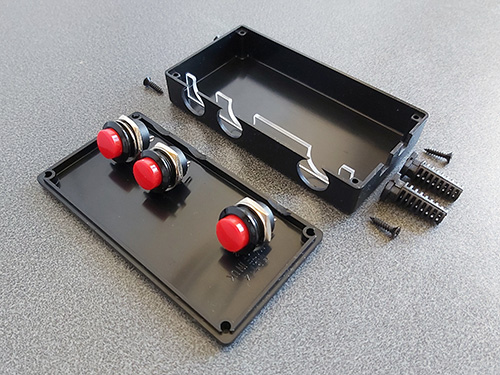
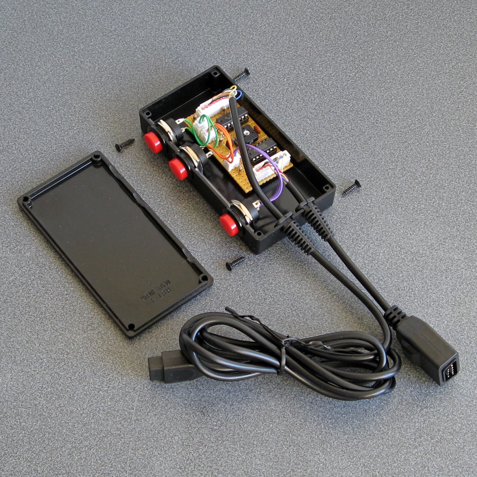
Whilst the epoxy was curing the final parts of the project could be assembled – a pair of start buttons had wires soldered to them with crimp connectors on the other end and a couple of rubber strips were cut to provide a bit of extra grip to the bottom of the adaptor. The various component parts of the project can be seen in the photo above.
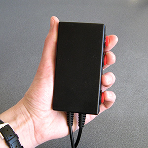
Everything does fit fairly neatly inside the enclosure, fortunately! After everything is assembled inside the bottom of the enclosure was screwed on and the rubber grip strips attached with double-sided sticky tape.
I still haven't been able to test this adaptor with any Mega CD games however it does work well in both Lethal Enforcers and Lethal Enforcers II: Gun Fighters on the stock Mega Drive so hopefully it will also work well in Mega CD games.

I'm pretty happy with how this project turned out. If you would like to assemble the adaptor yourself, you can find the schematic in the previous journal entry, and if you do build it I'd love to hear how you got on!
Adding some protective resistors to the Light Phaser to Mega Drive gun adaptors
Monday, 20th April 2020
Here's a quick update to the two Mega Drive light gun adaptor circuits, all to a few extra resistors in and around the adaptor and the console.
The real Sega Menacer receiver drives the TH line (used to indicate when the gun has seen light) directly from the output of a NOR gate with a 470Ω resistor in series. My circuit uses a transistor in the open-collector configuration with a 10KΩ resistor on the base input and a 1KΩ pull-up resistor, which is the same as the circuit used in the original Sega Light Phaser.
In a worst-case scenario the console could configure TH as an output, drive it high, and the Menacer adaptor could drive TH low at the same time. This would short the console's TH output to ground via the transistor, and might damage it (I'm not sure how these I/O ports are constructed internally). The TH output from a regular Sega Light Phaser would have the same problem, however that only pulses low briefly when it sees the light from the CRT whereas the TH output from the Menacer adaptor is latched and can stay low for a much longer time, increasing the risk. Resistors are cheap, so assuming the engineers at Sega know their hardware better than I do I thought it safer to add a 470Ω resistor on the TH output. This hasn't affected performance, as far as I can see. I also corrected the diagram to reference the BC548 as this is the transistor I tested with – the BC547 probably works too, however in the interest of accuracy I thought it best to stick with what I know works.
Sega Light Phaser to Sega Menacer adaptor
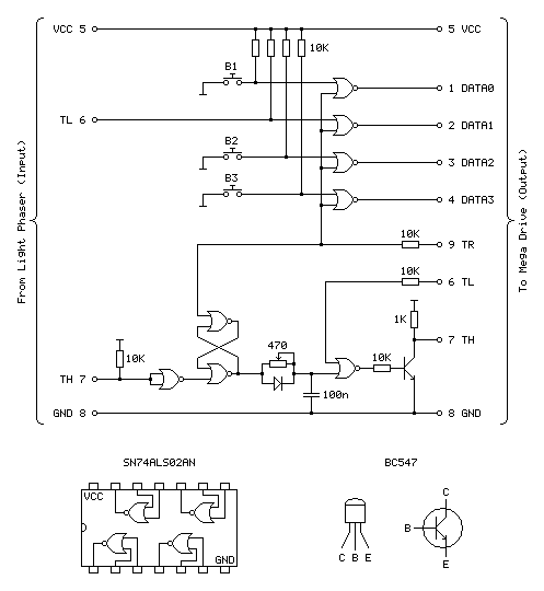
The Menacer circuit (as well as the original control pad) drives the DATA0~DATA3 lines directly so I haven't included any resistors there. I have, however, applied the same resistor changes to the Justifier adaptor:
Sega Light Phaser to Konami Justifier adaptor
As well as the 470Ω resistor on the TH input/output line I have added the 10KΩ resistors on the TL and TR input lines. I'm still not sure what these are for but as they are there in the Menacer adaptor and as Sega presumably know best I've included them here for completeness. As these are attached to inputs on the logic gates there should be very high impedance anyway, but it could be for protection in case the logic gates are improperly powered. What I do know is that the extra 10KΩ pull-ups on the TH inputs from the Light Phasers should protect against spurious TH outputs when either of the guns are unplugged.
I still haven't been able to test the circuit with any other games, but for now these two circuits seem to be holding up!
Simplifying the Light Phaser to Justifier adaptor to a two-chip solution
Saturday, 18th April 2020
In the previous post I mentioned I was dissatisfied with the optimisation of the Light Phaser to Justifier adaptor circuit. This was because I was using two quad two-input multiplexer chips (eight multiplexers total) but only using three multiplexers on each chip but also needed two inverter gates and so had to add a third chip to accommodate that requirement. It seemed like there must be a better solution, and after pondering this in the shower I think I found it.
One of the inverters is required for the transistor used to drive the TH line from the circuit. The TH line is bidirectional, and from our end of the circuit is either left floating (where it can rise high) or pulled directly to ground. To achieve this I was using an NPN transistor with the collector connected to TH, the emitter connected to ground and the base connected (via a resistor) to our logic signal. Unfortunately, such a transistor is switched on by a positive voltage and so a logic high at the input resulted in a logic low on TH, so to correct this an inverter was added.
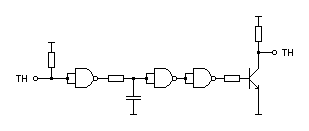
A much simpler solution is to get rid of the inverter and transistor entirely and to replace it with a reverse-biased diode, replacing three components with one:
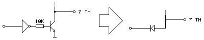
Current can only flow the diode if the voltage at the anode (right, connected to TH) is higher than the voltage at the cathode (left, connected to our logic signal). This means that if our logic signal is the same as the current state as TH then no current flows (and so we leave TH alone) and if our logic signal is high and TH is low then the diode is "backwards" and no current flows. The only way we can influence TH is if it is high and our logic signal is low, allowing current to flow through the diode, grounding TH – which is our desired outcome. One inverter is out of the way!
The other inverter is used to produce an inverted version of TH which is used when the console is retrieving the peripheral ID from the Justifier. We can use a multiplexer as an inverter by using the select pin as the input, tying the "0" input high and the "1" input low (that way when 0 is requested 1 is output and when 1 is requested 0 is output). The problem we have here is that all four multiplexers on a chip share a common selection pin, we need to invert TH, and neither of our two multiplexers is using TH as the select pin (one is using TR to select between the two guns and the other is using TL to globally enable or disable the guns).
The solution here is that we only need this inverted TH signal during the peripheral ID check which is carried out when the guns are globally disabled. When the guns are disabled we don't care about what the TR gun-selection multiplexer is doing, as whether the blue gun or pink gun is selected is irrelevant as the data never makes it to the console. We can therefore use the spare multiplexer on the TL-selected multiplexer chip to select between TR and TH, and use the output of this as the select pin into the multiplexer chip previously used to select between the two guns and use its spare multiplexer as the inverter.
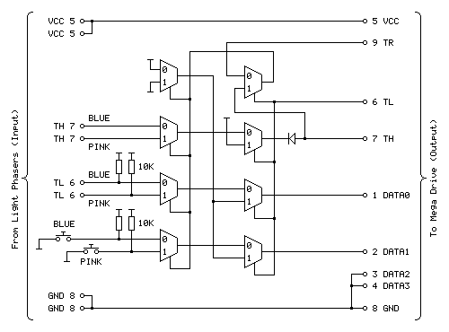
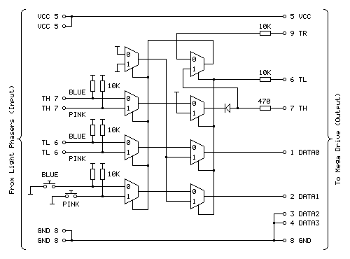
The revised circuit is shown above, the wiring is more complicated than the previous one however it takes advantage of all eight multiplexers on both chips and does away with the need to have an additional inverter logic chip and transistor driver circuit for TH.

The revised two-chip prototype is picture above, and has been tested successfully with Lethal Enforcers – performance doesn't seem to be any different from before, which seems to be a good sign!
Using Master System Light Phasers to play Konami Justifier games on the Mega Drive
Saturday, 18th April 2020
Following my adventures with building an adaptor that lets me use Sega Light Phaser guns in Sega Menacer games it seemed sensible to turn my attention to the other type of light gun for the Sega Mega Drive – the Konami Justifier.

These guns are unsurprisingly incompatible with the Sega Menacer and Sega Light Phaser and supported in even fewer games on the stock Mega Drive (only Lethal Enforcers and Lethal Enforcers II: Gun Fighters). However, these games are more in line with the type of light gun game that I like to play than what you'd find in the Menacer's library (even though the digitised sprites haven't aged particularly gracefully) and the guns are eye-wateringly expensive if you want to get a set of both for two-player games which makes the idea of a cheap adaptor to use the Master System's Light Phaser more appealing. And, of course, it's a fun challenge!
You may have noticed that the two guns in the photo at the top of the post are different colours, and unfortunately this is not purely cosmetic. The Justifier comes in distinct "player 1" and "player 2" variants, with the first gun plugging into the console and the second gun plugging into the bottom of the first gun using a modular connector in a daisy-chain configuration. This allowed Komani to sell console-specific blue player 1 guns and a generic pink player 2 gun that would work with the blue player 1 gun from any system. If you invited a friend over to play with you then you'd need to go out of your way to buy the specific player 2 gun (your friend's blue player 1 gun won't work), and as the blue gun was not sold separately you couldn't buy a game and "upgrade" to a light gun controller later, you'd need to buy one that came with a game and as a result both guns are now somewhat difficult to find and fairly expensive, especially the player 2 gun.
However, this arrangement should allow for a pretty neat solution where we can build a single adaptor that plugs into a controller port on the Mega Drive and provides two controller ports for the two Light Phaser guns rather than having to build two separator adaptors. Like the Menacer, the Justifier does have an extra button when compared to the Light Phaser however it's only one button this time (rather than three) and it's used as a Start button so both of these could be put on the adaptor unit itself between the two players.
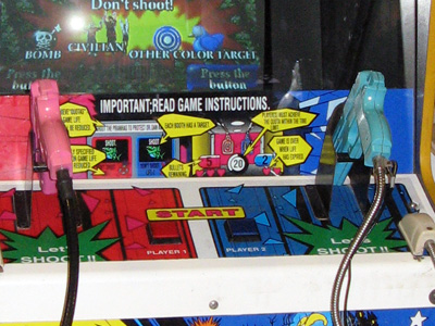
A Point Blank arcade machine with two Start buttons on the control panel between the two guns.
Without buying a pair of Justifier guns, how can it be studied so an adaptor can be built? In the case of the Menacer the receiver units can be bought cheaply and studied to figure out how they interface with the console and the patent document covers how it should work in high-level detail too. I have been unable to find such information for the Justifier. Fortunately Eke-Eke, the author of the Genesis Plus GX emulator, came to the rescue with the document gen_lightgun.pdf which goes into some detail about how the Justifier interfaces with the Mega Drive.
The key information to take into account here is that DATA0 is mapped to the trigger, DATA1 is mapped to the start button, TH is used for the light sensor, TR is used to select which of the two guns to query and TL is used as a general gun enable/disable line. As both guns share the same data lines for their triggers, start buttons and light sensors we can use multiplexers to select between the two guns.
The Mega Drive also needs to be able to detect when the Justifier is plugged in, and it does this by checking the state of the four DATA lines, once when TH is high and once when TH is low, then combining the bit values read in both states to form a single four-bit peripheral ID. The process was explained in more detail in an earlier post, however for the sake of simplicity to correctly return the device ID of %0001 we need to make sure that when TH is high all four data lines are low and when TH is low DATA2 and DATA3 should still be low and one or both of DATA0 and DATA1 should be high.
As DATA2 and DATA3 are always low and aren't used anywhere else they can just be tied low at all times and that should work. DATA0 and DATA1 should pass through the trigger/start button status (active low signals, so normally high) when the game is reading the button state but it looks like they should be forced low when TH is high. According to Eke-Eke's documentation: "I'm not sure why Justifier returns such values, maybe setting TH=1 will force input lines to 0".
My first attempt, therefore, was to use a NOR gate outputting to each of the two data lines with one input to each coming from the TH line and the other input coming from the inverted trigger/start button status. This way if TH was high both data lines would be forced low, otherwise it would output the inverted form of the input (and as the input to the NOR gate was already inverted, the final signal would be corrected – two wrongs do make a right in electronics!) This would not work if both trigger and start button were pressed, unfortunately, but maybe that wouldn't be a problem?
Happily, this worked in the menu for Lethal Enforcers, with the adaptor plugged in I was able to select the option to start a one- or two-player gun game! However, the game was completely unresponsive to the buttons. When writing an emulator you can make certain assumptions about how the hardware works, as long as the right values are in the right places when the software reads them. You also have the advantage of being privy to the internal state of the hardware that external devices might not be able to see! One important note in Eke-Eke's documentation is "this means the Justifier should return the following byte values when TH is set as output" – we can't directly tell whether a pin is set to an output or an input from outside the console, we can only see what its current signal level is. During normal gameplay TH is an active-low signal from the light gun's light sensor, and as a result TH is normally high which blocks the buttons from working. I had thought that maybe the game software would drive the TH pin low during its button-reading routine to allow the data to pass through but evidently the gun doesn't work this way.
Another issue is that whilst I can use a logic analyser to see what state the pins are in over a period of time, I can't tell at what point the console is reading those pins itself and making decisions based on what it sees. I could disassemble the game code to try to see how that's working, but I couldn't figure out any meaningful output from the disassembly tools I tried and couldn't find an appropriate debugging emulator so went back to trial and error.
The solution, I think, is in the TL pin being used to enable or disable the guns. I think that we should only mess around with forcing DATA0 and DATA1 high or low (based on the state of TH) when the guns are disabled, otherwise we let the button and light sensor state pass through. We can achieve this with two stages of multiplexers, one to select between the two guns (selected by TR) and another to globally enable/disable the guns (selected by TL). If we invert TH we can use this to drive the DATA0 and DATA1 lines when the guns are disabled, meaning that we also fix the problem where the gun wouldn't be detected if both buttons were held.
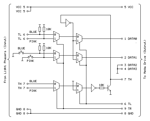
The above diagram shows the circuit I'm currently using to test with and it appears to work fairly well with Lethal Enforcers, being detected as a valid gun during startup and working in-game with both guns seemingly being handled correctly.
The first column of three multiplexers selects between the blue (player 1) and pink (player 2) gun inputs via the TR input. The top multiplexer handles the trigger (TL), the middle multiplexer handles the two Start buttons and the bottom multiplexer handles the light sensor inputs (TH). The second column of three multiplexers selects between the guns being enabled and guns being disabled via the TL input. When the guns are disabled (TL is high) DATA0 and DATA1 are driven by the inverse of TH to help provide the valid %0001 peripheral ID, allowing the adaptor to be detected as a Justifier.
The TH pin is a bit more challenging as it needs to be both an input and an output. At the moment when the guns are disabled it is driven high by tying the other input to the multiplexer high. The TH output is driven by a transistor; when the transistor is switched on it connects TH to ground (making it low) and when it is switched off it is left to float (normally floating high, but otherwise under the control of the console). As the transistor is switched on by a positive voltage this effectively acts as an inverter, hence the signal from the multiplexer to the transistor also needs to be inverted.

The prototype adaptor assembled on a solderless breadboard.
I'm not entirely happy with the way the circuit has been implemented, in particular the use of two multiplexer chips where only three of the four multiplexers are used and the need for an additional chip for the inverter gates. Multiplexer chips normally have a global enable/disable pin in addition to their data selector, which makes me wonder if such a pin could be useful. The 74HCT157 chips I'm using drive the outputs low when disabled which would not be very useful in this particular use case, however other chips are available that make the outputs high-impedence when disabled which may be more useful and allow for a circuit design that uses fewer parts.
There is also a slight issue of reliability and accuracy. When playing the game shots are generally fairly accurate and always register however they sometimes are offset horizontally. Eke-Eke's document points out that Lethal Enforcers does not use the console's horizontal counter latch so the inaccuracy may be a software issue – interestingly it seems Lethal Enforcers II does use the horizontal counter latch so when I can test with this cartridge it will be interesting to see whether accuracy is affected. More weirdly, the game does provide a "gun adjust" menu option where you can calibrate the game to compensate for any horizontal or vertical offset in the gun hardware however this does not seem to detect all shots and sometimes the accuracy is miles out! This also seems to be affected quite heavily by proximity to the screen, normally bringing the gun closer to the screen yields more accurate results however here it seems to make things worse. I'm not sure why this is and will continue to test the circuit to see if performance can be improved.
The completed Light Phaser to Menacer adaptor
Friday, 10th April 2020
In the last post I was having difficulty with the overall logic for handling the light sensor signal from the Sega Light Phaser and passing that along to the Mega Drive as if it was coming from the Menacer receiver. This involves latching the signal (instead of passing it along directly) and allowing the console to reset it once handled via the TR line. The signal needs to be delayed as well to simulate the delay from the overhead of the Menacer's wireless communications; without this delay the aiming is offset to the left. The signal is also gated using the TL line; I'm not entirely sure why this is done (some form of external interrupt inhibition?) but it's part of the original receiver so I thought it best to implement this for the sake of compatibility.
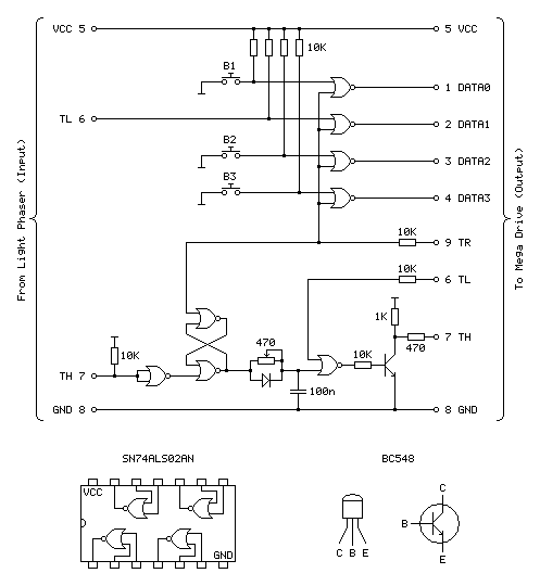
My main problem was that the CMOS NOR chip I had to hand was not triggering reliably with the signal from the light gun and the RC circuit used to delay that signal; I'd swapped it for a TTL NAND chip which then did work however the logic inputs to the latch were inverted (a simple NOR latch has active-high inputs and a simple NAND latch has active-low inputs) and to fix this would have required a lot of additional logic gates. I ordered an SN74ALS02AN TTL NOR chip and found that this worked very well, so have settled on the following circuit:
Update (20/04/2020): Please see this post for an updated diagram with a protective 470Ω resistor on the TH output
The four NOR gates towards the top of the circuit diagram are used to gate and invert the inputs from the four input buttons (one main trigger on the Light Phaser and three secondary function buttons on the adaptor itself). This is unchanged from the previous circuit and still works well.
The most important aspect of the circuit at the bottom of the diagram between the two TH pins is the latch made of two crossed-over NOR gates with the output from one going to the input of the other and vice-versa. The two inputs to this latch are normally low (TR from the console is driven directly and normally low, TH from the Light Phaser is normally high but inverted by a NOR gate with its legs tied together). When the reset pin TR goes high the output of the top gate must go low, as a NOR gate will always output low if either (or both) of its inputs are high:
| Inputs | Output | |
|---|---|---|
| A | B | Q = A+B |
| 0 | 0 | 1 |
| 0 | 1 | 0 |
| 1 | 0 | 0 |
| 1 | 1 | 0 |
If we assume that the other input to the lower NOR gate is also in its default low state then the two low inputs will result in a high output. This high input travels back to the top NOR gate's other input. This means that even when the TR pin goes back low again there is still a high input on that top NOR gate and so it maintains its low output.
When the Light Phaser sees light its TH output goes low, the NOR gate with its legs tied together inverts this to go high and the bottom input to the lower NOR gate in the latch goes high. This makes its output go low, which travels to the top NOR gate, making both inputs low (assuming TR is still low) and making the top NOR gate output a high which comes back down to the lower NOR gate so that even when the Light Phaser stops seeing light and the other input to the bottom NOR goes back to low there is still a high on the other pin, keeping the overall output low.
Effectively, what this means is that when the Light Phaser sees light the output of the latch goes low, and to return this back to a high the console needs to pulse the TR pin high.
The output of the latch goes to a delay circuit consisting of a resistor, capacitor and diode. This delay is required because the real Menacer introduces a delay between when it sees light and when it triggers the console's TH pin, and games are programmed to compensate for this. Without replicating this delay the aim is offset considerably to the left.
The logic gates are digital devices however still adhere to analogue rules and will treat certain voltages as high or low digital signals when they pass a certain threshold. The delay is implemented by slowing the rise or fall of the logic signal by charging a capacitor via a resistor, so whilst the logic signal at the output of the latch changes very quickly it will take the capacitor a while to charge or discharge via that resistor to a voltage level that is interpreted as a change of state by the following logic gate. The diode is there because we want the signal to be delayed when the gun sees light (when the logic level goes from high to low) but want it to change quickly when the latch is reset (going from low back to high again). When going from low to high there is a higher voltage to the left of the diode than there is across the capacitor to its right and so current can flow quickly through the diode, bypassing the slow resistor and charging up the capacitor quickly. When going from high to low the current can't flow backwards through the diode and so the capacitor has to discharge slowly through the resistor, providing the desired delay.
After this delay comes another NOR gate with its other input coming from the console's TL pin. I'm not entirely sure what this is for, as mentioned above, but it does at least allow us to buffer the signal from the RC delay circuit. The real receiver circuit then uses a final NOR gate with its inputs tied together to invert the latched signal before passing it to the console via a 470Ω resistor, but as I am already using an extra NOR gate to invert the input from the Light Phaser and have therefore used all four gates on one chip I instead use a transistor with a 1K pullup to invert the signal. The Light Phaser uses such a transistor circuit with the same 1K pullup resistor on its TH output so I thought it safe to use it here as it would be electrically compatible. The real receiver also includes 10K series resistors on its inputs from the TR and TL lines – I'm not entirely sure why but in case there was a good reason I thought I should use them here also!
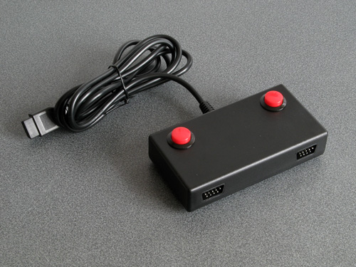
With the circuit appearing to work well I thought it was time to put it in an enclosure. I found a box that was a comfortable size to hold in one hand – it's about the same overall size of a Master System control pad other than being quite a bit fatter. This allowed me to put the three push buttons down the side of the box so they can all be pressed easily when gripping the box in one hand. The lid of the box has a lip that would interefere with the ability to tighten the nuts for the buttons and so I cut a small piece of acrylic that is slightly thicker than the lip and short enough that the box can be closed with it in place.
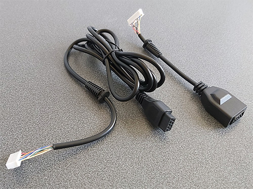
Of course, we need something to plug the Light Phaser into and a cable to plug the adaptor into the console with. A good source for these connectors is an inexpensive extension cable, so I bought one and cut it in two so I could use it for this project. After cutting the cable in two I installed strain reliefs and crimp connectors, and definitely remember to do that in that order! Interestingly I've bought a few of these cables recently from different suppliers (and with different moulding designs for the console plug and controller socket) and they've always been about half the length advertised but sold in packs of two.
I normally use pad board to solder my final circuits together. I start by roughly placing the components on the board where I think they should end up going, and when I've got the main parts in place I flip the board over and start soldering them down, using bare pieces of wire to make connections between components. I lay the bare pieces of wire as straight as possible and try to avoid crossing them over; where necessary I'll add a piece of insulation to a wire where it needs to cross another. Once as much of the board is placed in that fashion I'll solder thin wires between the points that can't have direct connections. It may not be the prettiest job (and making corrections afterwards is a bit of a pain) but it's worked well for me and I've found it allows for more compact layouts than stripboard.
Some crimp connectors were then added to the three push buttons and the whole circuit was installed in the box. Before the lid was screwed down the delay to correct the horizontal aim was calibrated using the 470Ω variable resistor. To adjust it the variable resistor was first set to its smallest resistance value and the tip of the light gun was touched to the centre of the screen. The aiming reticle is quite far to the left by default so the resistance of the variable resistor was then gradually increased to move the aiming reticle in the game right until it sits under the tip of the gun. The aim was then checked at the extreme left and right sides of the screen and if there were any dead zones the variable resistor was adjusted to move the aiming reticle away from the edge of the screen until it had a good range of motion across the entire width of the screen.
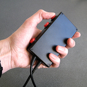
The two different grip styles for the adaptor buttons
The adaptor can be gripped in two different ways – in the regular position you have direct access to all three extra buttons with your fingers, and in the reversed position you have access to a single button at a time with your thumb. None of the games I've played on the Mega Drive use more than two extra buttons (and usually one of those is the bottom "Pause" button) but it's always good to have options!
I have tested the adaptor with the three Mega Drive games that support the Menacer — the six-in-one pack-in cartridge, T2: The Arcade Game and Body Count and am happy to report that it works with all three. I am not going to be able to test it with any Mega CD games as I do not have a Mega CD or a compatible flash cartridge, I'm afraid to say, but hopefully it will work just as well with those games.

The red and black theme was chosen to match the other accessories and I think it fits in rather well, even if it is a bit boxy-looking. If you are reading this and build the circuit yourself I'd love to hear how you get on!
Fixing the Menacer detection but breaking the accuracy of the aim tracking
Thursday, 26th March 2020
Since the last post about my experiments with using a Sega Light Phaser to play Mega Drive games I've had some good results and some disappointing ones that I'm still trying to work through.
The easy problem to solve was the handling of the buttons and making sure that the gun continued to be detected as a Menacer whenever a button was pressed. The previous circuit used active-high buttons (including an inverter to convert the active-low trigger from the Light Phaser into active-high signal) gated using the console's TH line via an AND gate. This meant that each button output a 0 when not pressed and 1 when pressed when TH was high, or a 0 in all cases whether TH was low or high.
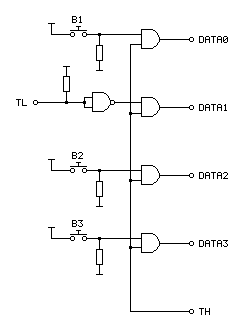
When looking at the patent for the Menacer it became apparent that the button data lines were coming from a four-bit counter that is reset by the console's TR pin going high. When looking at logic analyser traces from T2: The Arcade Game we can see that TR is held high during device detection at the main menu screen but goes low during gameplay, being periodically pulsed high when the game alternates between handling light detection (short pulse) and reading button presses (long pulse). Rather than active-high buttons with AND gates, active-low buttons with NOR gates would seem to work better, so I ordered some NOR gate chips and tried the following circuit:
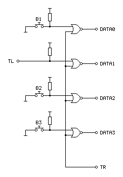
In the diagram above the TL on the left comes from the Light Phaser and the connections on the right go to the Mega Drive.
An OR gate will output a 1 if either of its inputs is a 1, to output a 0 both inputs have to be 0. A NOR gate inverts this output, so will output a 0 if either of the inputs is a 1 and will only output a 1 if both inputs are 0. When TR from the console is 1 it therefore forces the output to always be a 0, however if TR goes low to a 0 then the output is 0 if a button is released and 1 if a button is pressed – just what we needed.
Testing with T2: The Arcade Game I found that all of the buttons still worked during gameplay, and when pressing a button at the main menu the gun continued to be detected as a Menacer unlike the previous buggy implementation. All good so far!
I wanted to test with some other games, so ended up buying a copy of the six game cartridge that was originally bundled with the Menacer. I paid a little bit more and got a copy that came with the IR receiver, which is not much use without the gun however I thought it still might provider some interesting clues as to how to convert the signals from the Light Phaser to the Menacer protocol more correctly.
When the cartridge arrived I plopped it into my Mega Drive and was happy to see that the games mostly worked fine without any further tweaking. There was one fly in the ointment, however, an occasional message about the screen being too dark:
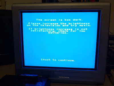
"The screen is too dark".
It would only do this occasionally when launching one of the six games and would then reset to the main intro and menu screen after shooting. Oddly, once a game was started I could quite happily move away from the TV to the other side of the room and the gun still worked reliably, so I'm not sure if this genuinely is an issue with the screen being too dark or if it's some problem with the way the gun is triggering the TH line on the console to indicate when it's seen light.
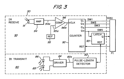
To try to get to the bottom of the issue I took apart the Menacer receiver and started sketching a circuit diagram based on the counter and NOR gate chips on the board. I then compared my scribbles to the circuit diagram in the patent, and found that the final implementation does appear to match the diagram in the patent pretty much exactly (I can't tell for certain as quite a lot of the circuitry is enclosed in a metal can, but all of the circuitry relating to the counter and NOR gate latch matches). This meant I was able to match up the console's pin connections to the diagram, which are unlabelled in the patent:
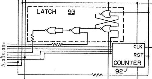
Pin connections for the Menacer receiver
It's not particularly clear due to how closely-packed the connections are in the diagram, however the important details are as follows:
- D0~D3 are connected to the counter directly, with D3 also going to set the latch at the top.
- TR resets the counter and the latch.
- TL appears to inhibit the output of the latch.
- TH only needs a 470Ω resistor between the output of the latch and the input to the console, not a common-emitter transistor driver.
I thought it would be neat if I could combine the function of the latch and the counter, so purchased a CD4017B decade counter chip as this has a handy clock inhibition input and wired it up as follows:
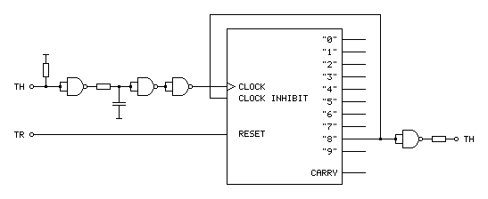
The clock input to this circuit comes from the TH output of the Light Phaser gun. This is an active-low signal so it needs to be inverted to properly clock the counter chip on the rising edge of the signal. It also needs to be delayed slightly for proper horizontal aiming (described in the previous post) so hence the additional RC circuit before the signal is fed to the counter chip.
With such a decade counter one of the 10 outputs labelled "0" to "9" is active at a time. After resetting the chip (by pulsing the reset pin high) "0" is high and "1" to "9" are low. When there is a rising edge at the clock input the chip counts up, so "0" goes low and "1" goes high, then "1" goes low and "2" goes high and so on and so forth. The "carry" output provides a rising edge clock signal when the counter overflows from "9" back to "0", allowing multiple chips to be chained together.
In the Menacer receiver the counter triggers the TH output latch on the fourth bit of a binary counter, i.e. when it reaches 8, so I've used the output of "8" as the output of the circuit. I've also fed this output back to the "clock inhibit" input of the counter chip. When this pin is low (which "8" will be when the counter is reset) it allows the counter to count up normally whenever the clock pin is pulsed. When the pin goes high (which "8" will be when we've seen eight pulses of light from the gun) it will inhibit the counter from counting any further, effectively locking it at "8". The only way out of this condition is to reset the chip, which the console does by pulsing the TR input line.
The only additional complication is that the console still expects an active low signal from the gun, so the final step is to invert the output from the counter.
Unfortunately, this does not work at all well. Games no longer seem to produce the "The screen is too dark" message, however aiming is extremely laggy and inaccurate. Checking the output of the counter with a logic probe seems to indicate erratic triggering. Using a different output from the counter (e.g. "4" or even "1") so that the counter "latches" sooner seems to improve things slightly but overall performance is still far worse in this arrangement. I'm not entirely sure why!
My next attempt was to simplify matters by using the exact latch circuit composed of NOR gates described in the patent, which worked just about as badly – the circuit still triggered eratically and accuracy was very poor. I have had issues with circuits not triggering properly before when using particular logic chips (it's why the circuit for my LCD Shutter Glasses adaptor has SN74LS14N Schmitt-trigger invertors on the logic inputs) so I thought I'd try replacing the CD4001B CMOS NOR gate chip I was using with the SN74ALS00AN TTL NAND gate chip I was using in previous experiments. The logic for a latch built from NAND gates is inverted to the logic of one built from NOR gates so it wasn't a straight swap but I don't have any other NOR gates in my parts bin. Somewhat surprisingly, with this new chip performance was greatly improved, though still not quite right.
For my next set of experiments I'm going to try replacing the CMOS NOR gate with the TTL NOR equivalent, though as that will involve waiting for parts to turn up in the post I thought I'd write a quick update on where I am so far. Fingers crossed this issue can be resolved easily and with a simple circuit!
Using a Master System Light Phaser in Mega Drive Menacer games
Wednesday, 18th March 2020
I'm a big fan of light gun games and have guns and games for most of the Sega systems – the Master System's Light Phaser, the Saturn's Virtua Gun and the Dreamcast's gun all get plenty of use.
One notable omission is the Sega Mega Drive and its Menacer light gun. This is a wireless gun with a range of bulky plastic accoutrements that represented Sega's efforts in the 16-bit generation; unfortunately only three games were released for it on the Mega Drive – a six-in-one collection of minigames that came bundled with the gun, a port of T2: The Arcade Game and the ferociously-expensive Body Count.
Ultimately the gun was a flop and they are not cheap to pick up second-hand (and are often missing most of the bits) so I haven't sought one out, however I did recently buy a cheap job lot of games which included a loose copy of T2: The Arcade Game.
I tried the game with the regular control pad and found it a disappointing experience (as most light games are when played with a pad!) so thought I'd see if I could get it to work with one of my Master System Light Phaser guns.
Of course, the game wouldn't detect that the gun was plugged in. Controllers on the Master System were generally very simple affairs, with one pin on the controller port per button (no multiplexing or serial data transfers here). On the regular control pad four data lines were used for the d-pad directions and two data lines (TL and TR) were used for the two buttons. These data lines were pulled high by the console and the control pad just contained switches that connected these data lines to ground when pressed for simple active-low logic.
The Light Phaser doesn't make use of the four d-pad data lines and only has one button so only uses one of those two data lines (TL) however it does make use of another pin on the controller (TH) for its light sensor. When this pin goes low the console latches the video chip's horizontal counter and the game software can read this and the free-running vertical counter to determine what point on the screen the console was outputting at the point the gun "saw" the light from the TV (and from this work out where the gun is aiming).
The Sega Light Phaser being used to play Rescue Mission on the Master System.
The Mega Drive is descended from the Master System's design and has very similar controller ports. The d-pad's four data lines are named DATA0 to DATA3, and by default the B and C buttons are mapped to the two TL and TR inputs like the two buttons on the Master System controller. However, the Mega Drive controller adds two extra buttons (A and Start). These two extra buttons share the TL and TR data lines and whether they are B and C or A and Start depends on the state of the TH line which is configured as an output from the console.
This use of the TH line to choose which buttons are mapped to which data lines is also used for controller identification. When TH is high the d-pad is mapped to the four data bits as normal. However, with a normal controller, when TH goes low data lines 2 and 3 (corresponding to left and right) go low also. This is normally impossible, as you can't physically press left and right simultaneously on a Master System controller, so a controller that ignores the state of the TH line won't be detected as a Mega Drive controller.
The device ID is encoded as a four-bit value according to the following logic:
| ID bit | TH state | Data bits |
|---|---|---|
| 3 | High | 3 OR 2 |
| 2 | High | 1 OR 0 |
| 1 | Low | 3 OR 2 |
| 0 | Low | 1 OR 0 |
For example, to read a regular controller's ID set TH to high and read the data lines. In this state the d-pad is mapped to the data lines. Bits 3 and 2 are mapped to to right and left. If neither is pressed both bits will be "1" as the inputs are active-low; 1 OR 1 is 1. If either left or right is pressed then one of the bits will be "0" but the other will be "1"; 0 OR 1 is also 1. The only way to get a zero is if both directions are pressed simultaneously which is not possible, so ID bit 3 will always be 1.
The same applies to ID bit 2, as this is uses data lines 1 and 0 which are mapped to the down and up buttons, so this will also always be a 1.
After setting TH low, we know that data lines 3 and 2 are forced to 0 so ID bit 1 is a 0.
Finally, ID bit 0 is based on data lines 1 and 0 which are still mapped to down and up and so will still be a 1. This all gives us a device ID of %1101, which is indeed the peripheral ID of a standard Mega Drive controller.
This is fine, but what does it mean for the Menacer? Well, that device has an ID of %0000. For this to happen we need to make sure that all four data lines are low whenever the console is reading the device ID. The easy way to do this is to take apart a Master System controller and to press all four d-pad buttons down simultaneously – doing so and starting the console with the T2 cartridge inserted makes the game think that a Menacer is plugged in!
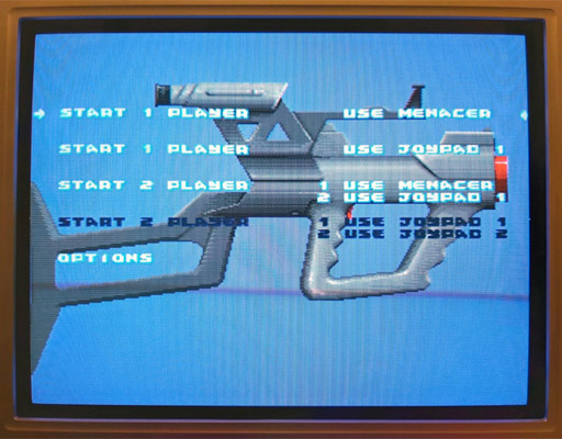
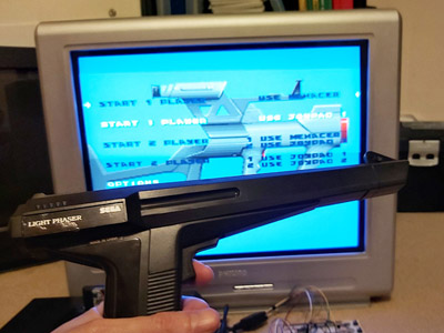
The Use Menacer options are white and selectable.
Somewhat unusually the Menacer's four buttons are mapped to the four data lines (instead of TL/TR) and are active high which means that if I start the game and let go of one of the Master System controller's buttons then it thinks I've pressed one of the Menacer's buttons (for example, releasing the "down" button makes DATA1 go high and the game thinks I'm pulling the trigger). Of course, I can't aim in this mode as there's no light gun input but it's good to see something is working!
I assumed that if TH is normally used for device identification I would start experimenting with using that to determine when the adaptor should output all zeroes. Considering the buttons need to be inverted to active-high logic too I thought it best to use an AND gate on each button so that if TH is high (normal state) the button input would pass through to the data line, but if TH is low (detection state) the data line would be forced low. I wired this up with an AND gate and four push buttons and the game still detected a Menacer and pressing a button in-game would now fire the weapon. Seeing that this worked, I removed one of the four push buttons that was previously used for the trigger button and used the TL data line from the Light Phaser instead via an inverter:
In the diagram above the TL on the left comes from the Light Phaser and the connections on the right go to the Mega Drive.
I assumed that the Menacer would also use the console's TH input for the light sensor from the gun (similar to the Light Phaser) so tried wiring up the Light Phaser's TH output to the Mega Drive's TH input. Moving the gun around the screen moved the aiming cursor around. Unfortunately, the aim was pretty far off:
The blue cursor should be under the gun, which is touching the screen.
The game placed the aiming cursor a consistent distance left of where the gun really was aiming. I assumed this was due to the game expecting a delay between when the gun saw the light from the screen and it sending a pulse to the console – unlike a wired gun that can send the signal back to the console very quickly the wireless Menacer converts the detected light pulse into an IR pulse that then needs to be handled by the receiving unit plugged into the console. By the time the console sees this pulse it will have moved further along the current scanline (right), so the game software works backwards (left) to an earlier point on the scanline. As I'm using a wired gun that transmits the signal much more quickly this left offset causes the aim to be incorrect.
The solution to this is to introduce our own delay into the signal, which I did with a crude RC circuit:
As I'd previously used a NAND chip to invert the signal from the trigger button I used three more of its gates to implement the delay. The first gate buffers the signal as the gun's TH is a common emitter output, so either connected to ground or pulled high via a resistor. This buffered signal then charges or discharges a capacitor to ground via a resistor – this provides most of the delay, and in my testing a 220Ω resistor and 100nF capacitor provided better aim. The next two gates buffer the signal again before driving a transistor for a common emitter output – as the console is also driving the TH line as an output I didn't want to directly drive it from the adaptor circuit and so the transistor seemed safer and is how the Light Phaser works anyway.
This is a crude circuit and has its limitations (very short pulses could be dropped entirely rather than delayed, for example) but it does at least seem to greatly improve the aim:

The cursor now lines up with the point on the screen the gun is touching.
The game is now fairly playable, though there is one notable flaw with the circuit: pressing any button at the main menu screen causes the game to assume the gun has been disconnected, disabling the Menacer options:
The Use Menacer options are dark and no longer selectable.
Clearly using the TH signal alone to disable the buttons is insufficient, we must need to also output 0 when TH is high for full compatibility with the peripheral ID reading and the gun must use some other technique to enable or disable the button data.
Fortunately, a copy of the Menacer patent can be downloaded from the Sega Retro website where it can be studied to see if it provides any more clues for how the Menacer works. It goes into some detail about how the gun communicates with the console, including this figure showing the gun:
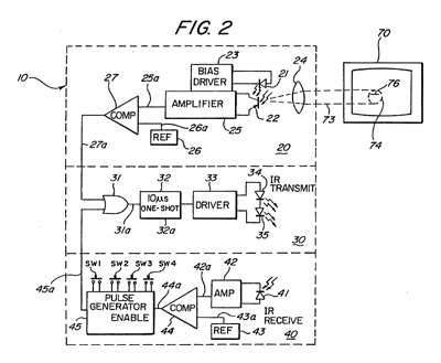
The centre portion of the image shows that infra-red signals from the gun are transmitted to the receiver in the form of 10µs pulses. The top portion of the image shows that these pulses can be generated by the gun's light sensor, so whenever the gun sees light it will send a 10µs IR pulse to the receiver. The bottom portion of the image shows the pulse generator used to encode the button presses; the button state is interpreted as a binary number and a corresponding number of IR pulses are sent: if SW1 is pressed then 1 pulse is sent, if SW2 is pressed then 2 pulses are sent, if SW3 is pressed then 4 pulses are sent and if SW4 is pressed then 8 pulses are sent. If multiple buttons are pressed then their values are added, so if SW1 (1) and SW3 (4) were pressed then five pulses would be sent up to a maximum of 15 pulses for all four buttons being pressed.
These button press pulses are only sent back to the console receiver after the gun receives an IR pulse from the receiver.
The receiver uses a counter chip to convert the IR pulses from the gun into button press or detected light pulses for the console. The duration of reset pulses are important here. The patent describes a standard counter reset pulse as being 2-3µs long and a main reset signal pulse as being about 10µs long. Any short reset pulse will reset the counter chip and latch. A long reset pulse will stil reset them, but also trigger a pulse of IR via the transmitter section at the bottom of the diagram. This IR pulse will cause the gun to send its button data back to the receiver, where the pulses will be counted by the counter chip and drive the DATA0 to DATA3 pins. After a certain delay to ensure that all button states have been sent the game software can read the button state and reset the counter, ready to read pulses from the light sensor in the gun. Bear in mind that the button state will have to be read before the active display starts, as the gun always sends an IR pulse when it sees light and this will cause the button presses to be miscounted.
Rather than pass every single detected pulse of light from the gun to the console it looks like the counter is used to detect eight pulses, after which it triggers a latch. This appears to be due to the assumption that when the gun is an expected distance away from the TV it will trigger on around 20 scanlines, and so by waiting for eight it will place the detected position roughly in the middle of those 20 lines.
All in all, this is a simple enough system but what does it mean for our convertor circuit? Will we need to add extra pulse length detectors and counters to make sure we send through the right sort of data?
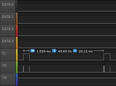
I captured the state of the controller port lines during gameplay and found the above logic traces. Each frame TL goes high briefly and is then low for the active part of the frame. Pin TR has very brief pulses, and these appear to be the reset pulses. If we zoom in, we can see these more clearly:
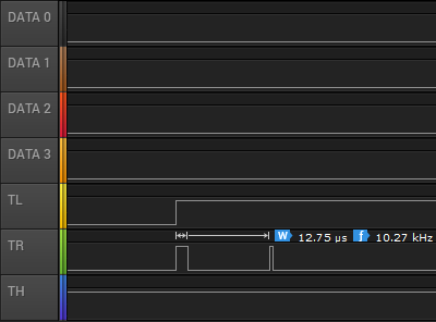
Here TR goes high for over 10µs and so must be the main reset pulse (used to read the button state) and the next pulse is around 3µs and so must be the regular counter reset pulse. The gap between these pulses is only 85µs, however – if the button IR pulses are 10µs long then this would not give us enough time to read them – even if there was no gap between them 15 pulses of 10µs would take 150µs. Either there is a delay of at least 85µs before the gun starts sending the button data or the timing is different in the real gun when compared to the patent information. There is a final 3µs reset pulse as TL falls and this pulse comes 1.435ms after the previous short reset pulse so that would provide plenty of time to receive the button press data before resetting the counter ready to detect light pulses.
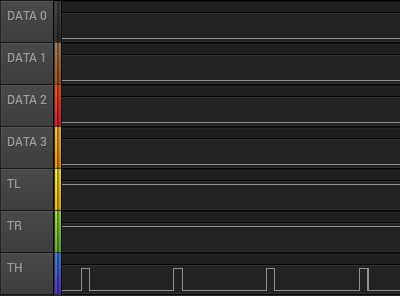
The next bit of the puzzle is what happens during the main menu when the Menacer is being detected. The traces are shown above. Both TL and TR are fixed high during this process. If we assume TR alone is used to reset the counters then holding this high would fix the data lines at %0000, identifying the controller as a Menacer. The TH line is also being pulsed here, possibly as the code is still checking to see if it could be some other type of controller.
If we force the output of the data lines to be 0 when TR is high (acting as a reset) then maybe this would work more reliably (and correctly) than when TH is low. I'll need to perform some further experiments, and also see whether the lack of the eight scanline delay before triggering the TH line to indicate detected light causes any other problems. I like the idea of a simple device that only uses logic chips to adapt the gun but if we need a more sophisticated circuit to time reset pulses and offset the vertical position maybe it would be better to switch to a microcontroller circuit. If that was the case, maybe the adaptor could also be programmed to work with games that use the Konami Justifier, another Mega Drive light gun that is incompatible with the Menacer.
If you'd like to see the circuit in action, I've uploaded a quick video on YouTube to accompany this post.
Repairing damaged plastic pegs
Friday, 4th October 2019
It's not uncommon for parts of old electronic devices to have damaged plastic pegs, like the one in this photo:
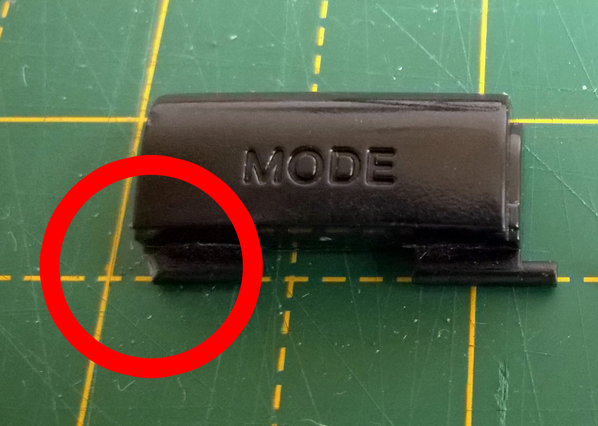
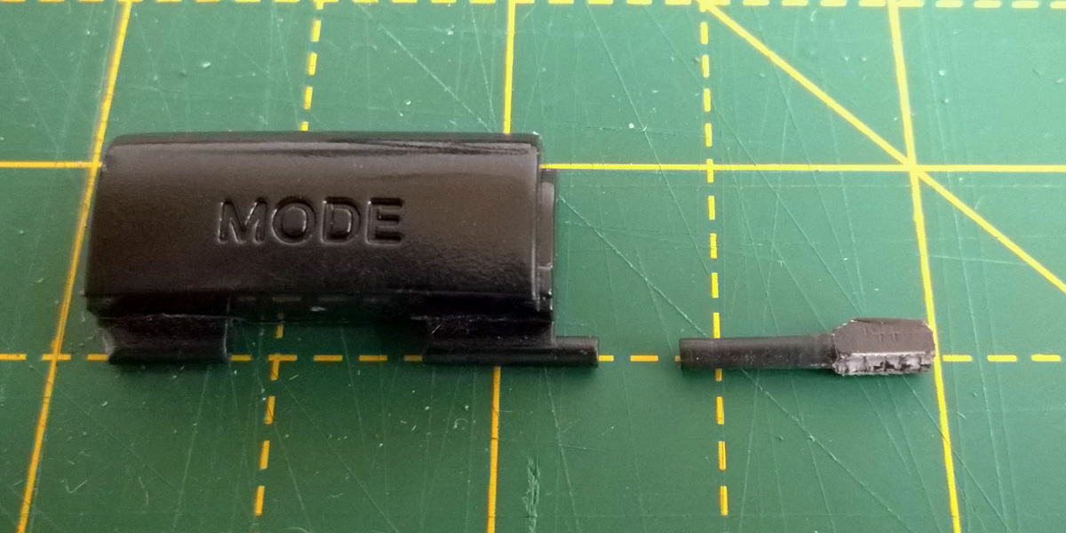
If you still have the snapped off plastic peg you may be able to glue it back on, but this can leave a weakened part that doesn't hold up very well. In other cases you might have lost the part entirely. This happened to me recently with the purchase of a six-button Mega Drive control pad. I ordered it from CeX's website and so couldn't see what condition it would be in until it arrived in the post. Unfortunately, it arrived in a filthy condition with a d-pad that only worked if you pressed the buttons very firmly and a non-functioning Mode button. I took it apart and was able to get the d-pad working again by cleaning the contacts. Whilst I left the rest of the plastic parts soaking in the sink to try to remove as much of the encrusted grime as possible I turned my attention to the faulty Mode button.
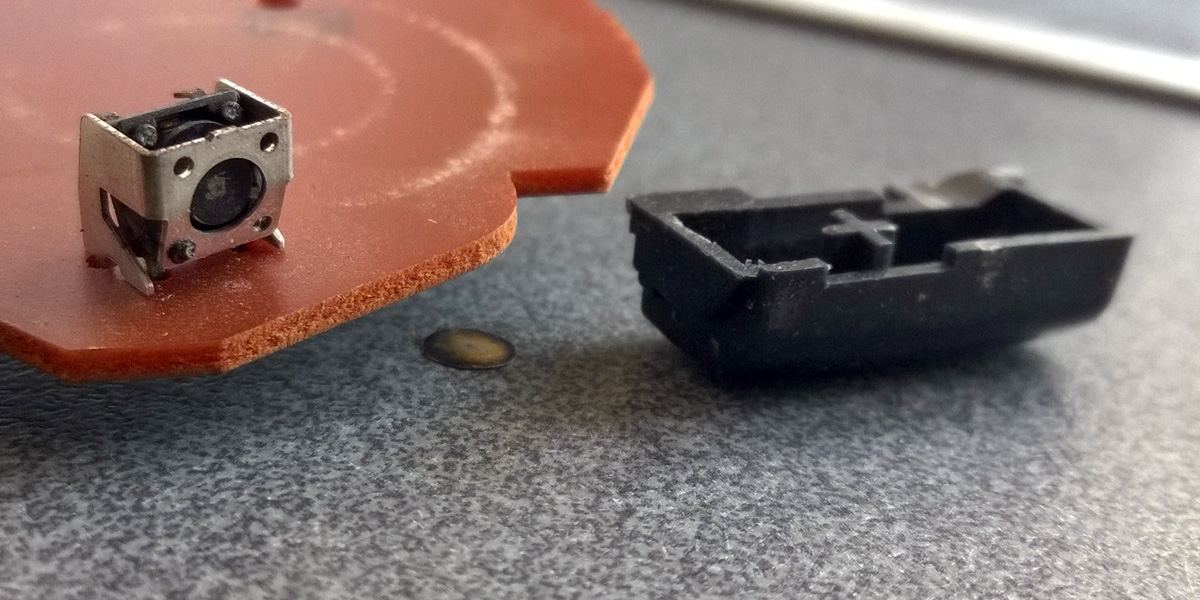
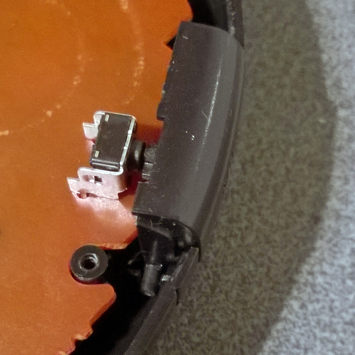
At some point the button must have been pushed in too firmly, damaging the tactile switch on the main board - the metal casing was bent and the plastic switch body had separated from it with the metal diaphragm that closes the contacts falling out. I've seen the same thing happen to some Sega Saturn control pads and fortunately had some spares in my parts bin so was able to swap that out easily. However, the pressure had snapped one of the plastic pegs of the Mode button off and it was nowhere to be found, so I needed to construct a replacement.
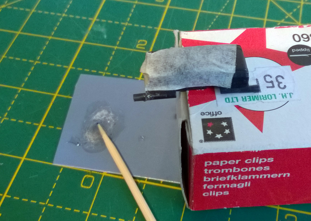
Fortunately, I have some scrap plastic parts from cutting out holes in plastic enclosures. In my case I needed to make a new peg that was 1.8mm in diameter, and had some 2mm sheet to use for this purpose. If I didn't have this then I could have gone online to buy a small 2mm thick sheet of ABS, but I prefer to recycle where possible!
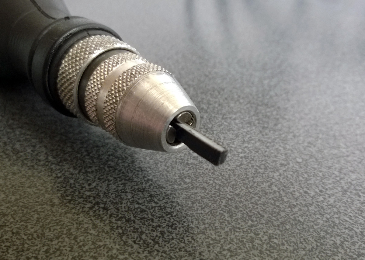
The first thing to do was to get a piece of plastic that was roughly the right size, so I cut a length with a cross-section of 2×2mm. To cut the plastic I scored it with a knife and then snapped it by gripping the short part with a pair of pliers and bending the longer part away from the score line.
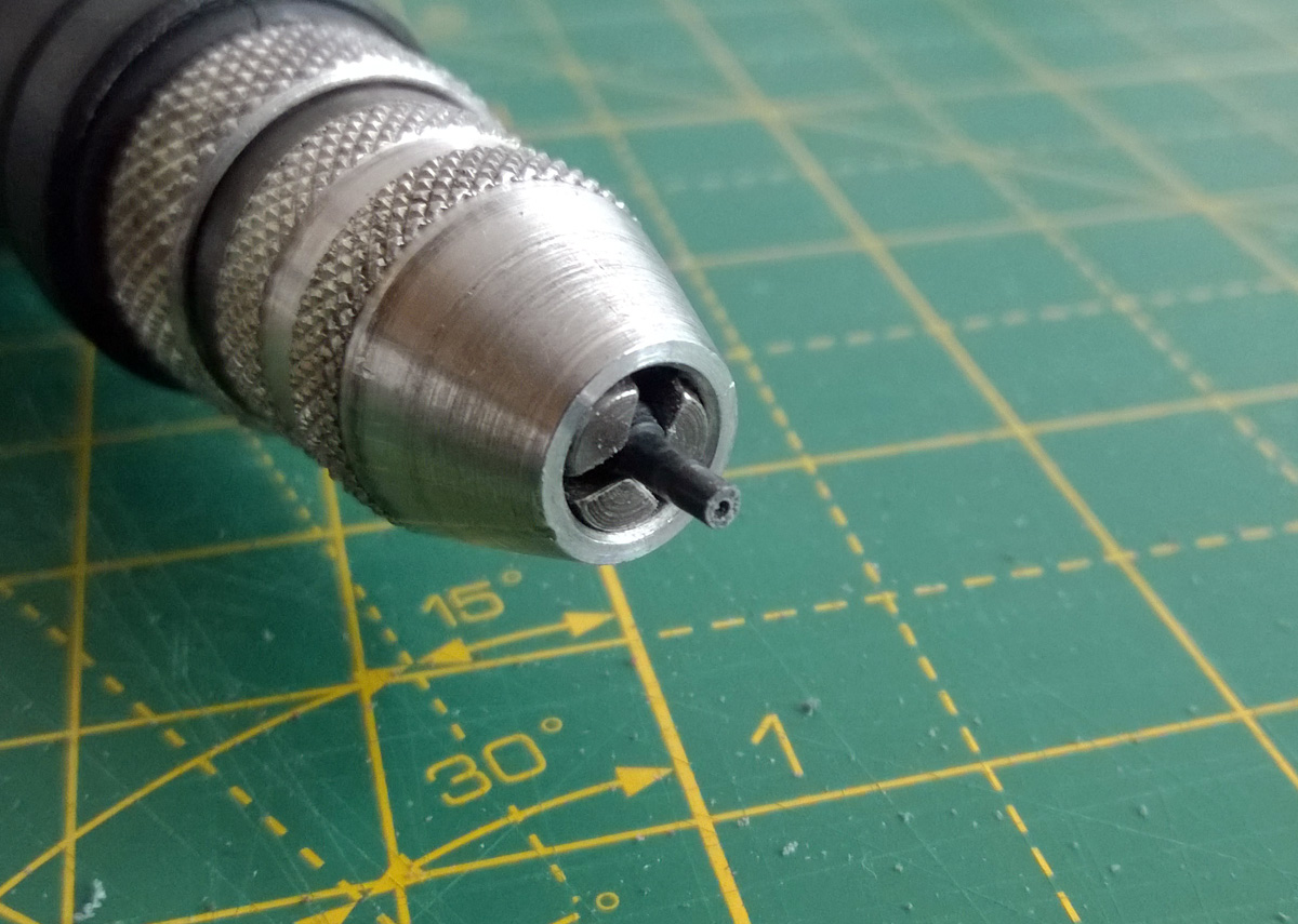
As the plastic peg needs to rotate in its slot inside the control pad it needs a round cross-section rather than a square one. To shape the peg into a rough cylinder I mounted it in the chuck of a rotary tool, as pictured above.

The rotary tool was then switched on and the plastic part held against a file. The photo above shows the start of this process with the peg beginning to take form. You need to work somewhat slowly with plastic as it gets hot when filing, cutting or drilling and if you let the heat build up it can melt and bend or gum up your tools. In my case I only used the file for a short period at a time before giving the piece time to cool back down. If I had been able to use my variable-speed rotary tool I could have set it to a lower speed to reduce the heat however the collet chuck on that tool wouldn't have been able to grip the work piece.
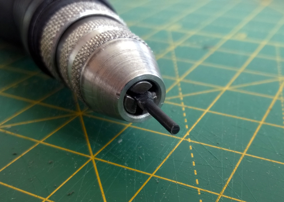
It doesn't take very long to get a nice round profile on the peg, though, even when working slowly (it's only a small piece, after all!) I carried on working it until I measured the 1.8mm diameter I was aiming for.
The above photo shows a size comparison between the new peg and the intact one on the Mode button. I've left the piece long (with the rough ending as a "handle") to make it easier to work with until it's time to fix it in place rather than cutting it to length straight away.
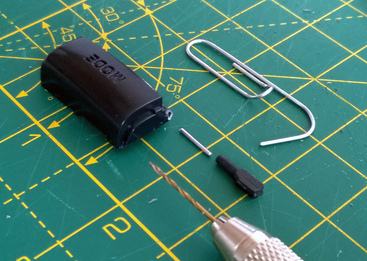
How to attach the new peg to the damaged button is the next issue to deal with. The rough surface of the snapped area of the button would make gluing difficult, though it could be filed flat to provide an easier surface to work with. My preferred technique, however, is to fix the new plastic peg with a metal pin made from a paper clip. This involves drilling narrow holes in the old button and the new peg to fit the metal pin through.

A pin vice is an invaluable tool for fine drilling work like this. I started with a very small drill bit to make the initial hole, being very careful to ensure I was drilling straight and in a well-centred location. This is something that needs to be taken slowly, especially on the original part. Once I had a pilot hole in the right place I switched to a larger drill bit that would drill a hole that the paper clip could fit into.
Starting the hole in the plastic peg might be easier by spinning the piece in your rotary tool and then bringing the stationary drill bit up to the end of it. As before be very careful about melting the plastic as once the hole is drilled the plastic is even thinner and will melt more easily – the peg is much shorter in the above photo than it was in previous photos as I accidentally melted it when I tried to drill all the way through in the rotary tool. I had to cut off the melted and distorted part to start again, only starting the hole in the rotary tool this time and then drilling the rest of the way slowly by hand. It's a good thing there was plenty of excess material!
The above photo shows the short length of paper clip that has been cut to connect the two plastic parts. Using a piece of wire like this should provide a lot of strength to the join – my experiences of gluing plastic to plastic have been very mixed, depending on the glue and plastic involved.
The parts in this case are all glued together with superglue and it seems to hold together quite well. The replacement peg was first cut to length before being glued. I coated one end of the paper clip rod in glue before pushing it into the hole on the button, then added glue to the other end and slid the new peg on. The end of the peg had a slightly protruding piece of the paper clip rod, so it was filed flush once the glue had set.
The uneven break still left a small gap in the join between the new peg and the Mode button body, so I filled it with a small amount of two-part epoxy resin. I used a toothpick to transfer a small amount of the mixed epoxy resin into the gap. This is always a bit messy so I protected the main button surface with masking tape. I also tidied up any "blobbiness" or glue that had otherwise run to undesired areas with a sharp knife before the epoxy had fully cured.
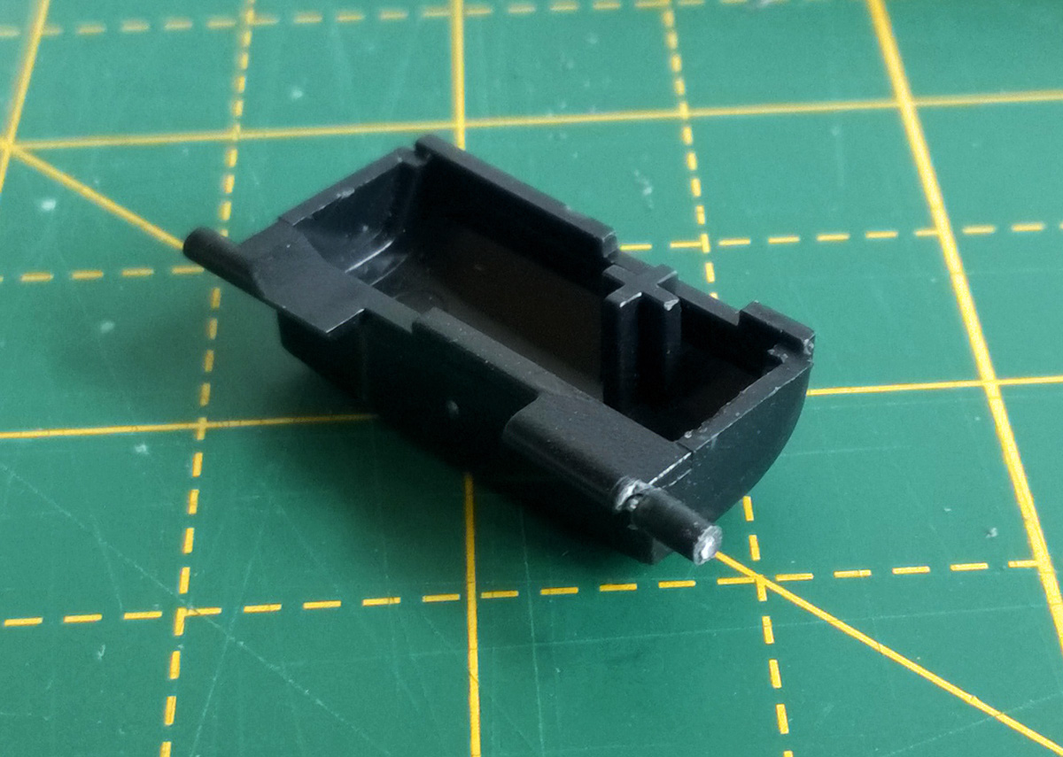
The button now sits properly in place inside the control pad and swings freely as it should. I could of course have just returned the control pad for a refund considering its condition but in spite of its problems it was still a well-priced item and I'm not sure they would have bothered to repair it. At least I know this way it'll be appreciated in its second life!
Subscribe to an RSS feed that only contains items with the Sega Mega Drive tag.