Printing graphics from a Cambridge Z88 on a Serial 8056 via the BASIC patch
Saturday, 29th November 2025

I've got a number of older computers that can print, but no printer for them. Quite often these computers require a serial printer, and so when a Serial 8056 printer popped up on eBay for around a tenner I picked it up. This is a thermal printer that takes fax paper rolls, so it seemed like a safe bet as far as consumables go (no need to source awkward cartridges, ink ribbons or spark paper) and the listing claimed it was intended for the Sinclair QL.
When it turned up I was a bit surprised by the plug on the end of the cable – two rows of eight pins, similar to a 16-way IDC connector, and not the phone jack style connector the QL needed. Fortunately the data (RD) and CTS pins were marked on the circuit board inside the printer and I was able to trace them out to the plug and bodge together a cable to plug it into my PC. Between articles from Format magazine, QL World and Popular Computing Weekly about the printer I was able to find the baud rate (1200), a few control codes for formatting and how to output graphics. Still puzzled by the non-QL plug I asked Reddit and that's when it was pointed out that the Serial 8056 is really a rebadged IBM PC Compact Printer originally sold for use with the PCjr. If my particular printer had been intended for use with the Sinclair QL then it would have included the appropriate adaptor in the box.
Knowing this, however, it made it easier to find information about the printer, including a reference manual, confirming the information I'd gleaned from the magazine articles about the Serial 8056.
One of the computers I had planned to use the printer with was my Cambridge Z88. Setting this up as a text printer was easy enough, but I'd been intrigued by a feature of the Z88 BASIC Patch, as described by the notes:
Unfortunately, the Z88 BASIC Patch source code release appears to be missing the printer code. I turned to Ghidra to disassemble the patch, and found the pertinent routines.
As the routines send a dump of the graphics window (the "map" in Z88 parlance) to the printer, I named the main routine DUMPMAP. One of the first things it does is to reset the printer via a routine I named DUMPRESET. This sends ESC @ to reset the printer (the Epson ESC/P reference may be useful here), then sends two line feeds. It falls through to the routine that is used to send bytes to the printer, which I've named DUMPWRCH:
                    *************************************************************************
                    * Resets the printer to its initial settings and outputs two line feeds *
                    *************************************************************************
                    DUMPRESET
ram:2bb5 3e 1b             LD           A,0x1b       ; ESC
ram:2bb7 cd c6 2b          CALL         DUMPWRCH
ram:2bba 3e 40             LD           A,'@'        ; ESC @ = Initialize printer
ram:2bbc cd c6 2b          CALL         DUMPWRCH
ram:2bbf 3e 0a             LD           A,'\n'       ; Line feed
ram:2bc1 cd c6 2b          CALL         DUMPWRCH
ram:2bc4 3e 0a             LD           A,'\n'       ; Line feed
                    *************************************************************************
                    * Write a byte to the serial port with a 1 second timeout               *
                    *************************************************************************
                    DUMPWRCH
ram:2bc6 f5                PUSH         AF
ram:2bc7 01 64 00          LD           BC,100       ; 100cs timeout
ram:2bca e7                RST          SYS
ram:2bcb 42                db           OS_Pbt       ; Write the byte to the serial port
ram:2bcc f1                POP          AF
ram:2bcd c9                RET
The DUMPRESET routine is also used at the very end of printing to reset the printer and ensure two line feeds appear after the graphics dump. Graphics data are sent as 8 pixel high rows with condensed line spacing, one byte per column. The relevant code that starts this process of each row is as follows: first the line spacing is set to 1/9-inch using ESC 3, a line feed is sent, there's a one second delay to give the mechanism time to advance and then graphics mode is entered with ESC L and a request to send 768 bytes:
ram:2b33 3e 1b             LD           A,0x1b       ; ESC
ram:2b35 cd c6 2b          CALL         DUMPWRCH
ram:2b38 3e 33             LD           A,'3'        ; ESC 3 = Set n/216-inch line spacing
ram:2b3a cd c6 2b          CALL         DUMPWRCH
ram:2b3d 3e 18             LD           A,24         ; 24/216 = 1/9-inch line spacing
ram:2b3f cd c6 2b          CALL         DUMPWRCH
ram:2b42 3e 0a             LD           A,'\n'       ; Line feed
ram:2b44 cd c6 2b          CALL         DUMPWRCH

ram:2b47 01 64 00          LD           BC,100       ; 100cs
ram:2b4a e7                RST          SYS
ram:2b4b 2d                db           OS_Tin       ; Wait for a key for 100cs

ram:2b4c 3e 1b             LD           A,0x1b       ; ESC
ram:2b4e cd c6 2b          CALL         DUMPWRCH
ram:2b51 3e 4c             LD           A,'L'        ; ESC L = Select 120-dpi graphics
ram:2b53 cd c6 2b          CALL         DUMPWRCH
ram:2b56 3e 00             LD           A,0          ; nL = 0
ram:2b58 cd c6 2b          CALL         DUMPWRCH
ram:2b5b 3e 03             LD           A,3          ; nH = 3: 768 bytes
ram:2b5d cd c6 2b          CALL         DUMPWRCH
The graphics window (map) is only 256 pixels wide, though, so why 768 bytes? Well, the printing code actually scales the image up before printing: it doubles the height and triples the width of each pixel. When outputting a row of graphics data, each column byte is sent three times:
ram:2b7c cd c6 2b          CALL         DUMPWRCH
ram:2b7f cd c6 2b          CALL         DUMPWRCH
ram:2b82 cd c6 2b          CALL         DUMPWRCH
This is all of the Epson-specific printer code, and fortunately it maps pretty well to the Serial 8056:
| Action | Epson ESC/P | Serial 8056 |
|---|---|---|
| Initialise printer | ESC @ | CAN |
| Set 1/9-inch line spacing | ESC 3 n=24 | ESC 1 |
| Output bitmapped graphics | ESC L n=768 [768 bytes] | ESC K n=512 [512 bytes] |
Ideally, the Epson codes could simply be patched with the equivalent Serial 8056 codes but there is one slight spanner in the works: the Serial 8056 needs a carriage return to be sent after each line and the code doesn't do that and there's no easy way to insert it at the end of the relevant printing routines.
However, it is possible to insert a carriage return at the start of each line, which means that each line will start by ending the preceding one. This does still leave the final line, but fortunately the code calls DUMPRESET after printing the last line and so an additional carriage return can be inserted at the start of that routine to terminate that line.
It's not quite as elegant a patch, as the order of some code needs to be adjusted rather than just patching the Epson codes with the equivalent Serial 8056 codes, but it's not too bad overall. The full list of code changes are as follows:
                    DUMPRESET
ram:2bb5 3e 1b             LD           A,0x1b       ; Change to CR: ?&2BB6=13
ram:2bb7 cd c6 2b          CALL         DUMPWRCH
ram:2bba 3e 40             LD           A,'@'        ; Change to ESC: ?&2BBB=27
ram:2bbc cd c6 2b          CALL         DUMPWRCH
ram:2bbf 3e 0a             LD           A,'\n'       ; Change to '2': ?&2BC0=50
ram:2bc1 cd c6 2b          CALL         DUMPWRCH
ram:2bc4 3e 0a             LD           A,'\n'
The need to insert an extra carriage return at the start of the reset routine means we can only output a single line feed after resetting the printer instead of the original two. You may also be wondering why the printer is "reset" with ESC 2 instead of CAN, as that would save a byte – in my case it doesn't appear that resetting the printer that way resets the line spacing, which means that the printer gets left in the 1/9-inch line spacing mode. ESC 2 explicitly restores the 1/6-inch (default) line spacing mode.
The code that runs at the start of each line of output is a bit more awkward to change, unfortunately. The original code currently works like this:
- Send ESC
- Send '3'
- Send 24
- Send LF
- Wait 100cs
However, our new code needs to do this instead:
- Send CR
- Send LF
- Wait 200cs*
- Send ESC
- Send '1'*
Three of the five operations line up, however two of them (sending a byte of data and introducing a delay, marked with an asterisk) are swapped, which means that two code blocks in the code need to be swapped. Very fortunately, the code for each operation is the same size (five bytes) which at least means that the code between them can be left in the same place.
ram:2b33 3e 1b             LD           A,0x1b      ; Change to CR: ?&2B34=13
ram:2b35 cd c6 2b          CALL         DUMPWRCH
ram:2b38 3e 33             LD           A,'3'       ; Change to LF: ?&2B39=10
ram:2b3a cd c6 2b          CALL         DUMPWRCH

ram:2b3d 3e 18             LD           A,24        ; Change to 200cs delay: ?&2B3D=1 ?&2B3E=200
ram:2b3f cd c6 2b          CALL         DUMPWRCH    ; ?&2B3F=0 ?&2B40=231 ?&2B41=45

ram:2b42 3e 0a             LD           A,'\n'      ; Change to ESC: ?&2B43=27
ram:2b44 cd c6 2b          CALL         DUMPWRCH

ram:2b47 01 64 00          LD           BC,100      ; Change to DUMPWRCH '1':
ram:2b4a e7                RST          SYS         ; ?&2B47=62 ?&2B48=49
ram:2b4b 2d                db           OS_Tin      ; ?&2B49=205 ?&2B4A=198 ?&2B4B=43
The time delay is handled by calling the OS input routine with the timeout delay specified in register BC. The original code used 100cs, i.e. 1 second. When I was testing the code I ran into some issues: the first few lines printed fine, but the last couple of lines ended up failing to print, with the preceding lines showing some junk characters at the end of each line. Extending the delay to 200cs fixed the issue, but I was not sure why the first few lines printed fine and the problem only manifested itself at the end of the print until I looked at the movement of the print head more carefully.
The test image I was using was a row of Sierpinski triangles, and so the rightmost pixels were mostly white in the early rows but increasingly black as the triangles widened towards the bottom of the image. It turns out that if the end of the line is white the print head returns back home early, and so the one second delay was enough when the print head was skipping the end of the line but not quite enough when it had to travel the full distance back to the left edge. Extending the delay to two seconds provides more than enough time for the carriage to return.
When it comes to sending the actual bitmap data to the printer only a simple modification is required:
ram:2b4c 3e 1b             LD           A,0x1b
ram:2b4e cd c6 2b          CALL         DUMPWRCH
ram:2b51 3e 4c             LD           A,'L'        ; Change to 'K': ?&2B52=75
ram:2b53 cd c6 2b          CALL         DUMPWRCH
ram:2b56 3e 00             LD           A,0
ram:2b58 cd c6 2b          CALL         DUMPWRCH
ram:2b5b 3e 03             LD           A,3          ; Change to 2: ?&2B5C=2
ram:2b5d cd c6 2b          CALL         DUMPWRCH
Instead of ESC L with an argument of 768 bytes (&0300) we need to send ESC K with an argument of 512 bytes (&0200). The code will still try to send 768 bytes by repeating each column of the 256-pixel wide image three times, so instead we need to only send each column twice:
ram:2b7c cd c6 2b          CALL         DUMPWRCH
ram:2b7f cd c6 2b          CALL         DUMPWRCH
ram:2b82 cd c6 2b          CALL         DUMPWRCH     ; Change to CALL <dummy>: ?&2B83=&B4
The final CALL could be replaced by three NOP bytes but rather than do that the address of the target is patched to &2BB4. This address contains a RET instruction as it's the final instruction of a nearby routine so effectively turns the CALL into a NOP.
This completes the patch itself; the only thing needed to do is to wrap it up into a neat installer. Here is the result of that, in BBC BASIC:
   10 REM Serial 8056 Patch for Z88 BASIC
   20 C%=0:FORA%=&2B03TO&2BF6:C%=C%+?A%:NEXT
   30 IFC%=&5BF1PRINT"Patch already applied.":END
   40 IFC%<>&5BB9PRINT"Please load Z88PATCH.BBC first.":END
   50 READA%,V%:REPEATA%?&2B00=V%:READA%,V%:UNTILA%<0
   60 PRINT"Patch applied: use CALL 11011 to print.":END
   70 DATA&B6,13,&BB,27,&C0,50
   80 DATA&34,13,&39,10,&3D,1,&3E,200,&3F,0,&40,231,&41,45
   90 DATA&43,27,&47,62,&48,49,&49,205,&4A,198,&4B,43
  100 DATA&52,75,&5C,2,&83,180,-1,0
Line 20 first calculates a checksum of the area targeted by the patch, which is then checked in lines 30 and 40 for two known states: Serial 8056 patch already applied and Z88PATCH loaded but Serial 8056 patch not applied. Line 50 reads the patch data itself (stored in lines 70 to 100) which is made up of addresses and patch value pairs; as all bytes to patch appear in the &2Bxx address range only the least significant byte of the address is stored.
In summary, if you have a Serial 8056 and a Cambridge Z88 and wish to print graphics from BBC BASIC you may find the Serial 8056 for Z88 patch useful. You will also need the Z88 BASIC Patch as a starting point.
1-Wire interfacing with the Cambridge Z88
Sunday, 17th December 2023
I've been having a tricky time buying LM35DZ analogue temperature sensors for a project recently. One pair of probes and a bag of loose components labelled LM35DZ turned out to be regular NPN transistors with a fake label on them, and another pair of probes ended up being DS18B20 digital temperature sensors.
Whilst the DS18B20 temperature sensors were useless for the project I had in mind they were still functioning components. These use the 1-Wire serial bus, a bus named for the way that its single data line can also be used to parasitically power the devices on the bus. Electrically the bus is open drain with a pull-up resistor that idles in the high state which any device can drive low. The master initiates all communication and you can have multiple peripheral devices connected to the bus in an arrangement called a MicroLAN.
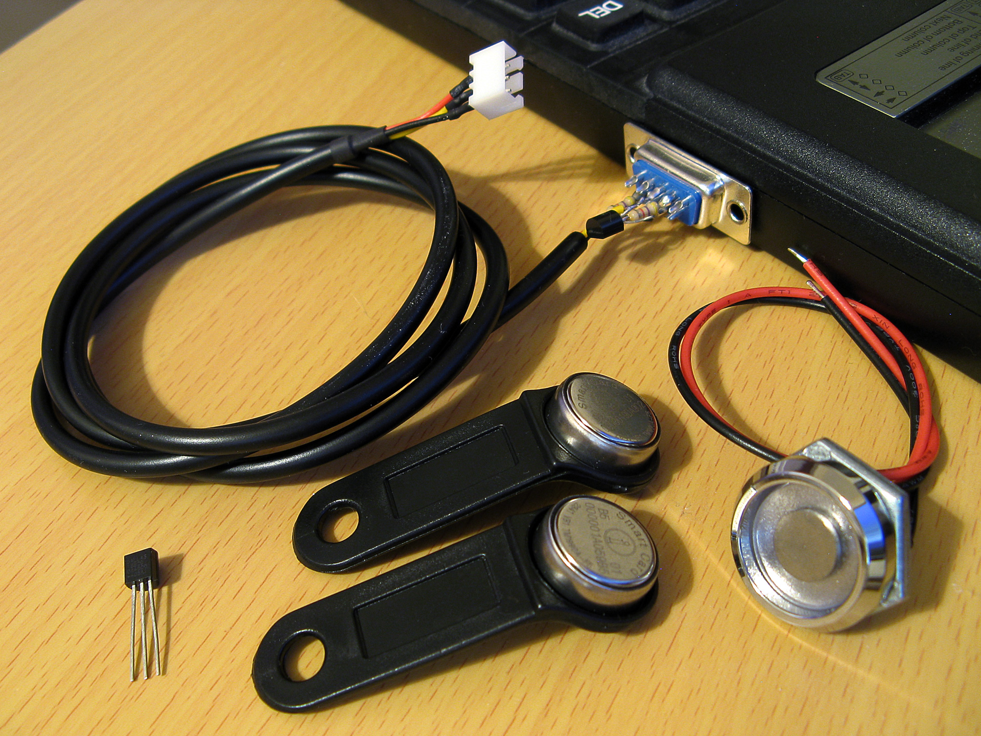
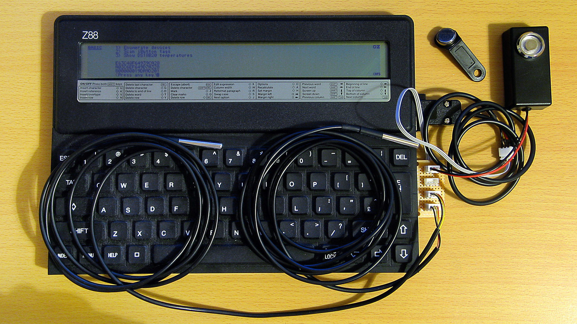
A selection of 1-Wire devices and a 1-Wire interface adaptor plugged into a Z88 computer
I'd had some limited experience working with the 1-Wire bus as part of my version of the Superprobe but now that I had a collection of temperature sensors I thought it might be worth revisiting, this time on the Cambridge Z88.
1-Wire adaptor for the Z88 serial port
To connect 1-Wire devices to the Z88 some sort of adaptor is required and one that plugged into the computer's serial port seemed like a sensible enough option. The Z88's serial port hardware normally handles all the communications for you however it is possible to directly control the logic levels of the serial port's output pins and read back the status of the input pins via some hardware registers.
The TXD line can be +5V for a logic 0 and -6V for a logic 1, adhering to the RS-232 standard. When idle TXD is in its logic 1 state, outputting -6V. Bit ITX (3) in the TXC (&E4) register can be used to invert the behaviour of the TXD pin, so by setting this bit we can change the state of the pin from -6V to +5V.
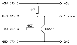
As we need to have an open-drain bus we can use an NPN transistor with the base connected to the TXD line via a current-limiting resistor, the emitter connected to ground and the collector driving the 1-Wire bus. By default the TXD pin will output -6V, the transistor will be switched off and the bus will be pulled high. When the TXD pin state is inverted it will output +5V, the transistor will switch on and drive the line low.
The state of the RXD line can be read directly via bit RXD (4) in the RXE (&E1) register. The lines appear to be weakly held to 0V and read back a 0 bit in this state, flipping to a 1 bit when the voltage rises above around 2V. In this case we can connect the 1-Wire bus directly to the RXD input and be able to read back the current state.
The circuit for the adaptor, including the 4.7K pull-up resistor, appears as follows:
This can be tested in a BASIC program. To determine the input state we can read from the RXE port register (&E1) and check the state of the RXD bit (4):
10 RXE=&E1:M_RXERXD=&10
20 REPEAT
30   PRINT ~(GET(RXE) AND M_RXERXD)
40 UNTIL FALSE
The mask value M_RXERXD is specified as 24=&10 to correspond to the bit four. When run this program displays &10 in hex (showing bit 4 is set and the bus level is therefore high) until the 1-Wire bus line is connected to ground, when the value changes to 0 (showing bit 4 is reset and the bus level is therefore low).
To change the output state we need to write to bit ITX (3) of the TXC register (&E4). However, when writing to the hardware port we only want to change that bit and leave the others alone. The TXC register is a write-only port, so we can't retrieve its previous state by reading from the port. Fortunately the OS maintains a copy of the last value written as a "soft copy" in RAM at address &04E4 and this can be read with the ? indirection operator:
10 TXC=&E4:M_TXCITX=&08
20 SC=&400
30 TXC_OLD=SC?TXC
40 PUT TXC,TXC_OLD OR M_TXCITX
50 IF INKEY(100)
60 PUT TXC,TXC_OLD
The above program reads the old state of the TXC port from the soft copy, ORs it with the mask of the ITX bit (23=&08) and then outputs that to the TXC port. This has the effect of inverting the TXD line, driving the 1-Wire bus low. The program then waits one second with a dummy keyboard read before restoring the old value of the TXC port to release the 1-Wire bus.
Normally if changing the state of the serial port it would be good manners to update the soft copy of the serial port state however as the program is just going to be sending short low pulses before returning the port to its previous state this step is omitted.
After testing that the circuit worked on a breadboard a more permanent version was assembled in a DE-9 shell as above. As the clips that hold in the DE-9 connector had to cut off to allow it to fit in the Z88's recessed port the circuit ended up being secured with copious amounts of hot glue, which is far from ideal, but nobody will see when it's all screwed back together.
Bit-level protocol
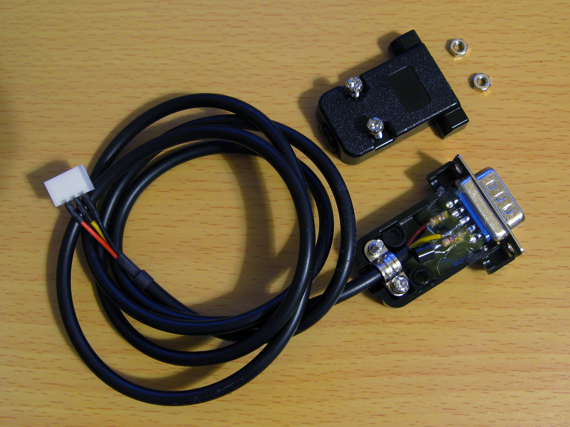
Now that we can electrically control the bus we need to know how to transfer data on it. This is done by timed pulses, where the bus master will hold the bus line low for a certain amount of time, release it, then check to see if any devices on the bus are holding it low in return. This is summarised in the following timing diagram from Microchip's AN1199, 1-Wire Communication with PIC Microcontroller:
The first thing that needs to be done is to reset all devices on the bus. This is done by holding the bus low for 480μs then releasing it for at least 480μs. If any peripheral devices are present on the bus they will drive the line low after the low pulse from the master, so the full reset procedure is as follows:
- Master drives bus low
- Delay 480μs
- Master releases bus high
- Delay 70μs
- Sample bus state: if high, no peripheral devices present, if low at least one device present.
- Delay 410μs
Once reset, data can be transmitted from the master to peripheral devices bit-by-bit in a similar fashion to the reset pulse, albeit with different timing.
To send a 0 bit:
- Master drives bus low
- Delay 60μs
- Master releases bus high
- Delay 10μs
To send a 1 bit:
- Master drives bus low
- Delay 6μs
- Master releases bus high
- Delay 64μs
Bytes are transferred as eight individual bits, least-significant bit first. The protocol is also tolerant of large delays between individual bits.
Once data has been sent to a peripheral, it may respond with data of its own. The master is still in control of clocking the data out of the peripheral, and the process is as follows:
- Master drives bus low
- Delay 6μs
- Master releases bus high
- Delay 9μs
- Sample bus state to read data bit from peripheral
- Delay 55μs
The overall timing for reading a bit is the same as the timing for sending a 1 bit (an initial 6μs low pulse from the master and a total bit time of 70μs) so in practice only one routine needs to be implemented and the value returned from the bus during read operations can be ignored during write operations.
Software choice for the Z88
I thought it would be nice to be able to interact with 1-Wire devices from a BASIC program. BBC BASIC on the Z88 does provide direct access to the hardware and would make controlling the 1-Wire bus line possible, as demonstrated earlier, however I don't think it would provide the timing accuracy required to produce the appropriate pulses from the master. Fortunately it does include a Z80 assembler and so a mixture of a BASIC program that provides the high-level routines and assembly snippets for the low-level 1-Wire protocol implementation seemed like an appropriate mix of languages.
When you CALL an assembly routine from BASIC the Z80's registers are initialised to the values of the corresponding static variables, for example A is set to A%, H to H%, L to L% etc. You can't return a value directly – for that you'd need USR – however it's a bit easier to just store the return value in memory and retrieve that from BASIC after the CALL returns.
A rough starting point for the 1-Wire program is as follows:
 10 REM 1-WIRE DEMO
 20 PROC_1W_INIT
 30 PRINT FN_1W_RESET
 40 END
 50 :
 60 REM 1-WIRE ROUTINES
 70 END
 80 DEFPROC_1W_INIT
 90 ow_code_size=256:DIM ow_code ow_code_size-1
100 RXE=&E1:M_RXERXD=&10
110 TXC=&E4:M_TXCITX=&08
120 SC=&400
130 FOR opt=0 TO 2 STEP 2
140   P%=ow_code
150   [OPT opt
160   .ow_buf DEFB 0 \ temporary transfer buffer
170   :
180   .ow_reset
190   IN A,(RXE):AND M_RXERXD:CP M_RXERXD:SBC A,A:LD (ow_buf),A:RET NZ \ check bus is idle
200   DI:LD A,(SC+TXC):OR M_TXCITX:OUT (TXC),A \ hold bus low
210   LD B,120:DJNZ P% \ delay
220   AND NOT M_TXCITX:OUT (TXC),A \ release bus
230   LD B,18:DJNZ P% \ delay
240   IN A,(RXE):AND M_RXERXD:CP M_RXERXD:CCF:SBC A,A:LD (ow_buf),A \ sample presence
250   LD B,100:DJNZ P% \ delay
260   EI:RET
270   :
280   ]
290 NEXT
300 ENDPROC
310 :
320 REM Resets bus, retuns TRUE if any devices are present
330 DEFFN_1W_RESET:CALL ow_reset:=?ow_buf=0
The first few lines are going to be where our BASIC program is. This calls the procedure PROC_1W_INIT which will set things up by assembling any required Z80 code. It then calls FN_1W_RESET which is a function that resets the 1-Wire bus and checks to see if any devices assert their presence.
PROC_1W_INIT starts by allocating some memory for the assembled code to live, defines some constants for the IO ports and then runs through the two passes of the assembly process in a loop. Within the assembly block is a variable (ow_buf) which will be used to store data due to be returned by the assembly routines. The ow_reset assembly routine then follows – this first checks to see if the bus is idle (floating high) and if so it disables interrupts, holds the bus low for 480μs, releases the bus and waits 70μs, samples the state of the bus to check for device presence (storing the result in ow_buf), then delays another 410μs.
The delay loops are simple DJNZ loops with B corresponding to the length of the delay and the timings were roughly calculated first based on the number of cycles each loop would take and the Z88's 3.2768MHz CPU clock speed. They were then adjusted slightly using a logic analyser to ensure the timing was as close as could be managed to the 1-Wire protocol's specifications.
The ow_reset routine has been written so that following a successful presence check ow_buf should contain 0, and if there is a problem it will contain a non-zero value. This is used by the FN_1W_RESET wrapper function which just calls ow_reset and returns TRUE if ow_buf is zero afterwards.
If you run the program you should see that the program will display 0 (FALSE) on the screen until a 1-Wire device is connected to the adaptor, at which point it will display -1 (TRUE) instead to indicate the device's presence. This isn't a very useful program, but shows how BASIC and assembly will be mixed to build the rest of the 1-Wire routines.
Sending and receiving bits and bytes
Now that we know a device is present on the bus after a reset we need to be able to send and receive bits and bytes. Sending a 0 bit is a bit simpler than resetting, as we don't need to check for any response – just hold the line low for 60μs then release it back high for 10μs. This can be implemented as follows:
.ow_put_0
DI
LD A,(SC+TXC):OR M_TXCITX:OUT (TXC),A \ hold bus low
LD B,15:DJNZ P% \ delay
AND NOT M_TXCITX:OUT (TXC),A \ release bus
NOP \ delay
EI:RET
Sending a 1 bit has the same overall timing as reading a bit, so instead of writing separate routines to send a 1 bit and read a bit just one routine is required that handles both situations:
.ow_put_1
DI
LD A,(SC+TXC):OR M_TXCITX:OUT (TXC),A \ hold bus low
NOP \ delay
AND NOT M_TXCITX:OUT (TXC),A \ release bus
PUSH HL:POP HL \ delay
IN A,(RXE):AND M_RXERXD:SUB M_RXERXD:CCF \ sample bit
LD A,(ow_buf):RRA:LD (ow_buf),A \ store bit
LD B,7:DJNZ P% \ delay
EI:RET
This holds the bus low for 6μs, releases it and waits 9μs, samples a bit from the bus and rotates it into the ow_buf transfer buffer, then waits 55μs.
These routines could be wrapped up for use in BASIC but it's not too useful to be able to send or receive single bits, normally we'd need to transfer whole 8-bit bytes. The ow_put_1 routine already handles updating the ow_buf with each received bit, so a byte receiving routine can be put together by just calling ow_put_1 eight times in a loop:
.ow_get_byte
LD B,8 \ 8 bits to receive
.ow_get_loop
PUSH BC:CALL ow_put_1:POP BC \ receive single bit
DJNZ ow_get_loop \ loop
LD A,(ow_buf):RET \ store
A send routine can be put together with a similar loop that shifts out the bit to send and then calls either the ow_put_0 or ow_put_1 routine depending on whether it's a 0 or 1 bit that's required. Bits will usually be shifted out into the carry register, so a new ow_put_carry routine that sends the bit stored in the carry flag makes this a bit easier, e.g.
.ow_put_carry
JR C,ow_put_1
JR ow_put_0
...which will be called by the ow_put_byte routine, as follows:
.ow_put_byte
LD C,A:LD B,8 \ value to send in C, send 8 bits
.ow_put_loop
SRL C:PUSH BC:CALL ow_put_carry:POP BC \ shift and send single bit
DJNZ ow_put_loop \ loop
RET
It is also quite useful to be able to send or receive blocks of data at once – for example, sending or receiving the 64-bit device IDs requires sending or receiving 8 bytes of data at a time. To complement ow_get_byte and ow_put_byte we can write ow_get_bytes and ow_put_bytes routines to send or receive the block of data addressed by HL, length BC:
.ow_get_bytes
LD A,B:OR C:RET Z:DEC BC \ have we finished?
PUSH BC:CALL ow_get_byte:POP BC \ get a byte
LD (HL),A:INC HL:JR ow_get_bytes \ store and loop
:
.ow_put_bytes
LD A,B:OR C:RET Z:DEC BC \ have we finished?
LD A,(HL):INC HL \ fetch
PUSH BC:CALL ow_put_byte:POP BC:JR ow_put_bytes \ send and loop
All of these can now be wrapped up as procedures or functions so they can be more easily used from a BASIC program:
REM Transmits a single byte
DEFPROC_1W_PUT(A%)CALL ow_put_byte:ENDPROC
REM Transmits a block of bytes
DEFPROC_1W_PUTS(L%,C%)LOCAL H%,B%:H%=L%DIV256:B%=C%DIV256:CALL ow_put_bytes:ENDPROC
REM Receives a single byte
DEFFN_1W_GET:CALL ow_get_byte:=?ow_buf
REM Receives a block of bytes
DEFPROC_1W_GETS(L%,C%)LOCAL H%,B%:H%=L%DIV256:B%=C%DIV256:CALL ow_get_bytes:ENDPROC
BASIC's integer variables are 32-bit integers so when passing the 16-bit address or length parameters the target register is the least-significant one (L for HL, C for BC) and the most-significant register (H or B) is populated by dividing the value by 256.
This can all be put together in the following demonstration program. It initialises the routines, resets the bus and checks for presence, then sends the "read ROM" command &33 which will make any connected devices respond with their ROM ID. It then reads back the eight bytes corresponding to the device ID then prints them back in hexadecimal.
 10 DIM ID 7:REM Storage for device ID
 20 PROC_1W_INIT
 30 IF FN_1W_RESET=FALSE PRINT "No devices found.":END
 40 PROC_1W_PUT(&33):REM "Read ROM" command
 50 PROC_1W_GETS(ID,8):REM Read eight bytes of device ID
 60 FOR I=7 TO 0 STEP -1:PRINT ~ID?I;:NEXT:PRINT:REM Print device ID bytes
 70 END
 80 :
 90 REM 1-WIRE ROUTINES
100 END
110 DEFPROC_1W_INIT
120 ow_code_size=256:DIM ow_code ow_code_size-1
130 RXE=&E1:M_RXERXD=&10
140 TXC=&E4:M_TXCITX=&08
150 SC=&400
160 FOR opt=0 TO 2 STEP 2
170   P%=ow_code
180   [OPT opt
190   .ow_buf DEFB 0 \ temporary transfer buffer
200   :
210   .ow_reset
220   IN A,(RXE):AND M_RXERXD:CP M_RXERXD:SBC A,A:LD (ow_buf),A:RET NZ \ check bus is idle
230   DI:LD A,(SC+TXC):OR M_TXCITX:OUT (TXC),A \ hold bus low
240   LD B,120:DJNZ P% \ delay
250   AND NOT M_TXCITX:OUT (TXC),A \ release bus
260   LD B,18:DJNZ P% \ delay
270   IN A,(RXE):AND M_RXERXD:CP M_RXERXD:CCF:SBC A,A:LD (ow_buf),A \ sample presence
280   LD B,100:DJNZ P% \ delay
290   EI:RET
300   :
310   .ow_put_carry
320   JR C,ow_put_1 \ fall-through
330   :
340   .ow_put_0
350   DI
360   LD A,(SC+TXC):OR M_TXCITX:OUT (TXC),A \ hold bus low
370   LD B,15:DJNZ P% \ delay
380   AND NOT M_TXCITX:OUT (TXC),A \ release bus
390   NOP \ delay
400   EI:RET
410   :
420   .ow_put_1
430   DI
440   LD A,(SC+TXC):OR M_TXCITX:OUT (TXC),A \ hold bus low
450   NOP \ delay
460   AND NOT M_TXCITX:OUT (TXC),A \ release bus
470   PUSH HL:POP HL \ delay
480   IN A,(RXE):AND M_RXERXD:SUB M_RXERXD:CCF \ sample bit
490   LD A,(ow_buf):RRA:LD (ow_buf),A \ store bit
500   LD B,7:DJNZ P% \ delay
510   EI:RET
520   :
530   .ow_put_byte
540   LD C,A:LD B,8 \ value to send in C, send 8 bits
550   .ow_put_loop
560   SRL C:PUSH BC:CALL ow_put_carry:POP BC \ shift and send single bit
570   DJNZ ow_put_loop \ loop
580   RET
590   :
600   .ow_put_bytes
610   LD A,B:OR C:RET Z:DEC BC \ have we finished?
620   LD A,(HL):INC HL \ fetch
630   PUSH BC:CALL ow_put_byte:POP BC:JR ow_put_bytes \ send and loop
640   :
650   .ow_get_byte
660   LD B,8 \ 8 bits to receive
670   .ow_get_loop
680   PUSH BC:CALL ow_put_1:POP BC \ receive single bit
690   DJNZ ow_get_loop \ loop
700   LD A,(ow_buf):RET \ store
710   :
720   .ow_get_bytes
730   LD A,B:OR C:RET Z:DEC BC \ have we finished?
740   PUSH BC:CALL ow_get_byte:POP BC \ get a byte
750   LD (HL),A:INC HL:JR ow_get_bytes \ store and loop
760   :
770   ]
780 NEXT
790 IF P%-ow_code>ow_code_size PRINT"Code size: "P%-ow_code:END
800 ENDPROC
810 :
820 REM Resets bus, retuns TRUE if any devices are present
830 DEFFN_1W_RESET:CALL ow_reset:=?ow_buf=0
840 REM Transmits a single byte
850 DEFPROC_1W_PUT(A%)CALL ow_put_byte:ENDPROC
860 REM Transmits a block of bytes
870 DEFPROC_1W_PUTS(L%,C%)LOCAL H%,B%:H%=L%DIV256:B%=C%DIV256:CALL ow_put_bytes:ENDPROC
880 REM Receives a single byte
890 DEFFN_1W_GET:CALL ow_get_byte:=?ow_buf
900 REM Receives a block of bytes
910 DEFPROC_1W_GETS(L%,C%)LOCAL H%,B%:H%=L%DIV256:B%=C%DIV256:CALL ow_get_bytes:ENDPROC
When connected to an iButton fob the program prints
55 0 0 1 A0 1A 57 1
...which matches the ID printed on it.
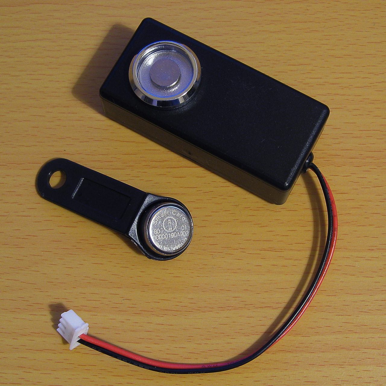
An example of a TM1990A iButton fob (middle) along with the probe used to read it (top)
When connected to a DS18B20 temperature sensor the program prints
B9 0 0 1 D1 97 5D 28
The least significant byte of the 64-bit ID is the family code – &01 for the iButton fob indicates it's a "silicon serial number" type device and &28 for the DS18B20 indicates it's a "programmable resolution digital thermometer".
The 1-Wire bus supports multiple peripheral devices connected to a single master. If we try that we still get something that looks like an ID back:
11 0 0 1 80 12 55 0
This happens because it's an open-drain bus and any device holding the line low will take priority over any device releasing the line high. In effect the data read back is ANDed together, so the most-significant byte received is &55 AND &B9 which gives us the &11 we see. Fortunately that most-significant byte does give us a good opportunity to detect such invalid data!
Error detection with a CRC
Some data payloads include a CRC value. The most-significant byte of a 64-bit device ID is such a CRC, with the least-significant byte being the family code. The exact details for the CRC calculation can be found in the article Understanding and Using Cyclic Redundancy Checks with Maxim 1-Wire and iButton Products however for our purposes a Z80 implementation can be written as follows:
.ow_crc
LD B,8:LD DE,(ow_buf):LD D,A \ E = accumulated CRC, D = value to add
.ow_crc_loop
LD A,E:XOR D:SRL D:SRL A:JR C,ow_crc_odd \ XOR and shift bits
SRL E:DJNZ ow_crc_loop:LD A,E:LD (ow_buf),A:RET \ even CRC value
.ow_crc_odd:SRL E:LD A,&8C:XOR E:LD E,A:DJNZ ow_crc_loop:LD (ow_buf),A:RET \ odd CRC value
:
.ow_crc_block
XOR A:LD (ow_buf),A \ reset CRC
.ow_crc_block_loop
LD A,B:OR C:LD A,(ow_buf):RET Z:DEC BC \ have we finished?
LD A,(HL):INC HL:PUSH BC:CALL ow_crc:POP BC:JR ow_crc_block_loop \ update CRC
ow_crc updates the current calculated CRC value (stored in ow_buf) with the next data byte from the accumulator. ow_crc_block calculates the CRC for a block of data pointed to by HL, length BC, using the ow_crc routine. A couple of BASIC functions can then be written, one to calculate the CRC of a block of data and another to check that the last byte of the block corresponds to the CRC of the preceding data:
REM Calculates the CRC of a block of data
DEFFN_1W_CRC(L%,C%)LOCAL H%,B%:H%=L% DIV256:B%=C%DIV256:CALL ow_crc_block:=?ow_buf
REM Checks if a CRC at the end of a block of data matches
DEFFN_1W_CRC_CHECK(L%,C%)=FN_1W_CRC(L%,C%)=(L%?C%)
These two can now be used to check that a device ID is valid. The CRC is also appended to other data reports, such as reading the scratchpad memory of a temperature sensor, so it's a useful routine to have. A new program which checks the CRC is as follows:
 10 DIM ID 7
 20 PROC_1W_INIT
 30 REPEAT
 40   REPEAT UNTIL FN_1W_RESET:REM Wait for device to be present
 50   PROC_1W_PUT(&33):REM Read ROM
 60   PROC_1W_GETS(ID,8):REM Fetch ID
 70   IF FN_1W_CRC_CHECK(ID,7) VDU 7:PRINT "Detected ";FN_1W_ID$(ID);" at ";TIME$:REM Print if valid
 80   REPEAT UNTIL FN_1W_RESET=FALSE:REM Wait for device to be disconnected
 90 UNTIL FALSE
100 END
110 :
120 REM 1-WIRE ROUTINES
130 END
140 DEFPROC_1W_INIT
150 ow_code_size=256:DIM ow_code ow_code_size-1
160 RXE=&E1:M_RXERXD=&10
170 TXC=&E4:M_TXCITX=&08
180 SC=&400
190 FOR opt=0 TO 2 STEP 2
200   P%=ow_code
210   [OPT opt
220   .ow_buf DEFB 0 \ temporary transfer buffer
230   .ow_conf DEFB 0 \ stores last bit conflict index
240   :
250   .ow_reset
260   IN A,(RXE):AND M_RXERXD:CP M_RXERXD:SBC A,A:LD (ow_buf),A:RET NZ \ check bus is idle
270   DI:LD A,(SC+TXC):OR M_TXCITX:OUT (TXC),A \ hold bus low
280   LD B,120:DJNZ P% \ delay
290   AND NOT M_TXCITX:OUT (TXC),A \ release bus
300   LD B,18:DJNZ P% \ delay
310   IN A,(RXE):AND M_RXERXD:CP M_RXERXD:CCF:SBC A,A:LD (ow_buf),A \ sample presence
320   LD B,100:DJNZ P% \ delay
330   EI:RET
340   :
350   .ow_put_carry
360   JR C,ow_put_1 \ fall-through
370   :
380   .ow_put_0
390   DI
400   LD A,(SC+TXC):OR M_TXCITX:OUT (TXC),A \ hold bus low
410   LD B,15:DJNZ P% \ delay
420   AND NOT M_TXCITX:OUT (TXC),A \ release bus
430   NOP \ delay
440   EI:RET
450   :
460   .ow_put_1
470   DI
480   LD A,(SC+TXC):OR M_TXCITX:OUT (TXC),A \ hold bus low
490   NOP \ delay
500   AND NOT M_TXCITX:OUT (TXC),A \ release bus
510   PUSH HL:POP HL \ delay
520   IN A,(RXE):AND M_RXERXD:SUB M_RXERXD:CCF \ sample bit
530   LD A,(ow_buf):RRA:LD (ow_buf),A \ store bit
540   LD B,7:DJNZ P% \ delay
550   EI:RET
560   :
570   .ow_put_byte
580   LD C,A:LD B,8 \ value to send in C, send 8 bits
590   .ow_put_loop
600   SRL C:PUSH BC:CALL ow_put_carry:POP BC \ shift and send single bit
610   DJNZ ow_put_loop \ loop
620   RET
630   :
640   .ow_put_bytes
650   LD A,B:OR C:RET Z:DEC BC \ have we finished?
660   LD A,(HL):INC HL \ fetch
670   PUSH BC:CALL ow_put_byte:POP BC:JR ow_put_bytes \ send and loop
680   :
690   .ow_get_byte
700   LD B,8 \ 8 bits to receive
710   .ow_get_loop
720   PUSH BC:CALL ow_put_1:POP BC \ receive single bit
730   DJNZ ow_get_loop \ loop
740   LD A,(ow_buf):RET \ store
750   :
760   .ow_get_bytes
770   LD A,B:OR C:RET Z:DEC BC \ have we finished?
780   PUSH BC:CALL ow_get_byte:POP BC \ get a byte
790   LD (HL),A:INC HL:JR ow_get_bytes \ store and loop
800   :
810   .ow_crc
820   LD B,8:LD DE,(ow_buf):LD D,A \ E = accumulated CRC, D = value to add
830   .ow_crc_loop
840   LD A,E:XOR D:SRL D:SRL A:JR C,ow_crc_odd \ XOR and shift bits
850   SRL E:DJNZ ow_crc_loop:LD A,E:LD (ow_buf),A:RET \ even CRC value
860   .ow_crc_odd:SRL E:LD A,&8C:XOR E:LD E,A:DJNZ ow_crc_loop:LD (ow_buf),A:RET \ odd CRC value
870   :
880   .ow_crc_block
890   XOR A:LD (ow_buf),A \ reset CRC
900   .ow_crc_block_loop
910   LD A,B:OR C:LD A,(ow_buf):RET Z:DEC BC \ have we finished?
920   LD A,(HL):INC HL:PUSH BC:CALL ow_crc:POP BC:JR ow_crc_block_loop \ update CRC
930   ]
940 NEXT
950 IF P%-ow_code>ow_code_size PRINT"Code size: "P%-ow_code:END
960 ENDPROC
970 :
980 REM Resets bus, retuns TRUE if any devices are present
990 DEFFN_1W_RESET:CALL ow_reset:=?ow_buf=0
1000 REM Transmits a single byte
1010 DEFPROC_1W_PUT(A%)CALL ow_put_byte:ENDPROC
1020 REM Transmits a block of bytes
1030 DEFPROC_1W_PUTS(L%,C%)LOCAL H%,B%:H%=L%DIV256:B%=C%DIV256:CALL ow_put_bytes:ENDPROC
1040 REM Receives a single byte
1050 DEFFN_1W_GET:CALL ow_get_byte:=?ow_buf
1060 REM Receives a block of bytes
1070 DEFPROC_1W_GETS(L%,C%)LOCAL H%,B%:H%=L%DIV256:B%=C%DIV256:CALL ow_get_bytes:ENDPROC
1080 :
1090 REM Converts ID bytes into string
1100 DEFFN_1W_ID$(ID)LOCAL I%:S$="":FOR I%=7 TO 0 STEP -1:IF ID?I%>15:S$=S$+STR$~(ID?I%):NEXT:=S$:ELSE:S$=S$+"0"+STR$~(ID?I%):NEXT:=S$
1110 REM Converts string into ID bytes
1120 DEFPROC_1W_ID$(ID,ID$)LOCAL I%:FOR I%=0 TO 7:ID?I%=EVAL("&"+MID$(ID$,15-I%*2,2)):NEXT:ENDPROC
1130 :
1140 REM Calculates the CRC of a block of data
1150 DEFFN_1W_CRC(L%,C%)LOCAL H%,B%:H%=L% DIV256:B%=C%DIV256:CALL ow_crc_block:=?ow_buf
1160 REM Checks if a CRC at the end of a block of data matches
1170 DEFFN_1W_CRC_CHECK(L%,C%)=FN_1W_CRC(L%,C%)=(L%?C%)
The program waits for a device to be present, reads its ID, then prints it to the screen along with the date and time if its CRC is valid. It then waits for the device to be removed before looping around to check again. This allows you to tap iButtons to a reader and it will display the relevant ID, for example. It also adds a couple of utility routines – a function, FN_1W_ID$(ID), which turns a block of ID data bytes into a string and a procedure, PROC_1W_ID$(ID,ID$), which does the opposite.
Enumerating the 1-Wire bus
It's certainly useful to be able to detect a single device on the 1-Wire bus however it would be more useful to detect multiple devices and be able to address them individually. Checking every single possible 64-bit address for a response would take far too long, but fortunately there is a way to very quickly enumerate every peripheral device on the bus by means of a binary search.
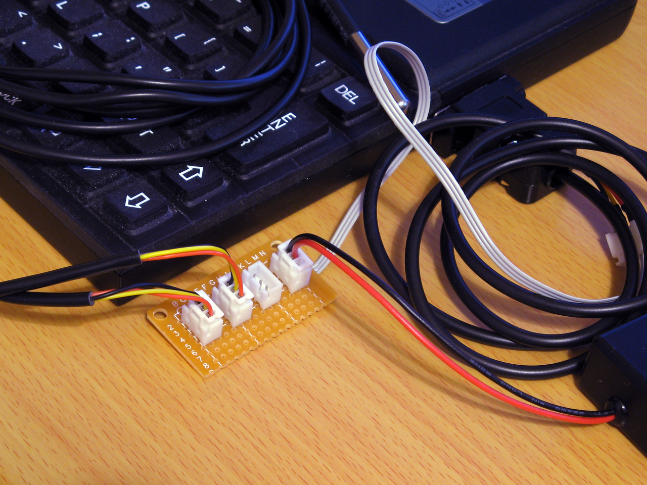
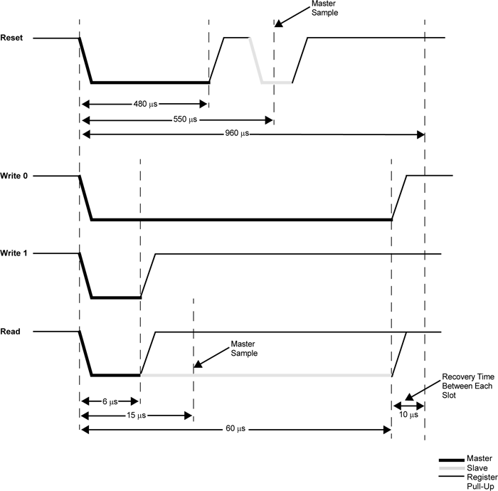
Each socket is wired in parallel to allow multiple 1-Wire devices to be connected to the Z88
To start the search, the master sends either the normal search command &F0 or the alarm/conditional search command &EC. When using the conditional search only devices that are in some sort of alarm state will respond, allowing the master to more quickly identify the devices that need attention. As we're interested in all devices we'll use the normal search command &F0.
After issuing the search command all active devices on the bus will start to report their ID, bit by bit. Each device will send each bit twice, firstly in its normal state and then again in an inverted state. Due to the open-drain nature of the bus, this allows the master to detect conflicting bit values – if all active devices have a 0 in the current bit position then the bus will read 0 then 1, if all active devices have a 1 in the current bit position then the bus will read 1 then 0 but if there is a mixture of zeroes and ones then the bus will read 0 then 0.
After this the master sends a single bit that tells the active peripheral devices which bit it has identified. If this does not match the peripheral's current bit value then the peripheral will go into an idle state and stop responding until the bus is reset again, but if it does match then the device will continue to send bits of its ID. This allows the master to walk down both branches of the binary tree when searching for device IDs when it detects a conflict, by first selecting one bit value in one iteration of the search and then the other bit value in another iteration of the search.
The full procedure for enumerating the bus is more explicitly described in the app note 1-Wire Search Algorithm, and can be implemented with the following Z80 assembly code:
.ow_conf DEFB 0 \ stores last bit conflict index
:
.ow_search
LD DE,(ow_conf):LD D,0:LD C,1:LD B,64
.ow_search_loop
PUSH BC:CALL ow_put_1:CALL ow_put_1:POP BC:RLCA:RLCA \ get bit, !bit
AND 3:JR Z,ow_search_conf \ 00 = conflict
DEC A:JR Z,ow_search_1 \ 01 = 0 bit
DEC A:JR Z,ow_search_0 \ 10 =  1 bit
SCF:RET \ report failure
.ow_search_conf
LD A,B:CP E \ how does bit index compare to last conflict
JR C,ow_search_0_conf \ 0, update current discrepancy
JR Z,ow_search_1 \ 1, no update
LD A,(HL):AND C:JR NZ,ow_search_advance \ old bit = 1, just advance
LD D,B:JR ow_search_advance \ old bit = 0, update current discrepancy
.ow_search_1:LD A,C:OR (HL):LD (HL),A:JR ow_search_advance
.ow_search_0_conf:LD D,B \ fall-through
.ow_search_0:LD A,C:CPL:AND (HL):LD (HL),A \ fall-through
.ow_search_advance
LD A,(HL):AND C:SUB C:CCF:PUSH BC:CALL ow_put_carry:POP BC \ return the ID bit
RLC C:JR NC,P%+3:INC HL \ advance mask
DJNZ ow_search_loop
LD A,D:LD (ow_conf),A
XOR A:LD (ow_buf),A:RET \ report success
A pair of BASIC wrappers can make using this search routine a bit easier:
REM Starts enumerating devices on the bus
DEFPROC_1W_SEARCH_RESET:?ow_conf=TRUE:ENDPROC
REM Searches for next device on bus. Pass search type &F0 for all devices, &EC for alarming devices. Returns TRUE if next device found
DEFFN_1W_SEARCH(A%,ID)IF ?ow_conf=0:=FALSE ELSE IF FN_1W_RESET=0:=FALSE ELSE PROC_1W_PUT(A%):H%=ID DIV256:L%=ID:CALL ow_search:=?ow_buf=0
The "reset" routine just sets the last bit conflict index to -1 (TRUE=-1) and FN_1W_SEARCH will search based on the search type (&F0 for all devices, &EC for alarming devices only), the current ID and last conflict index and will return TRUE if an ID was found or FALSE if no more IDs were found.
A snippet of code that enumerates all devices on the bus and displays their IDs is as follows:
PROC_1W_SEARCH_RESET
REPEAT F%=FN_1W_SEARCH(&F0,ID):IF F% PRINT FN_1W_ID$(ID)
UNTIL F%=FALSE
Reading temperature sensors
So far the examples have been fairly uninteresting, but we now have enough support code to do something useful with devices on a 1-Wire network. The DS18B20 temperature sensors that inspired this whole project are probably the easiest way to show how useful the 1-Wire bus can be.
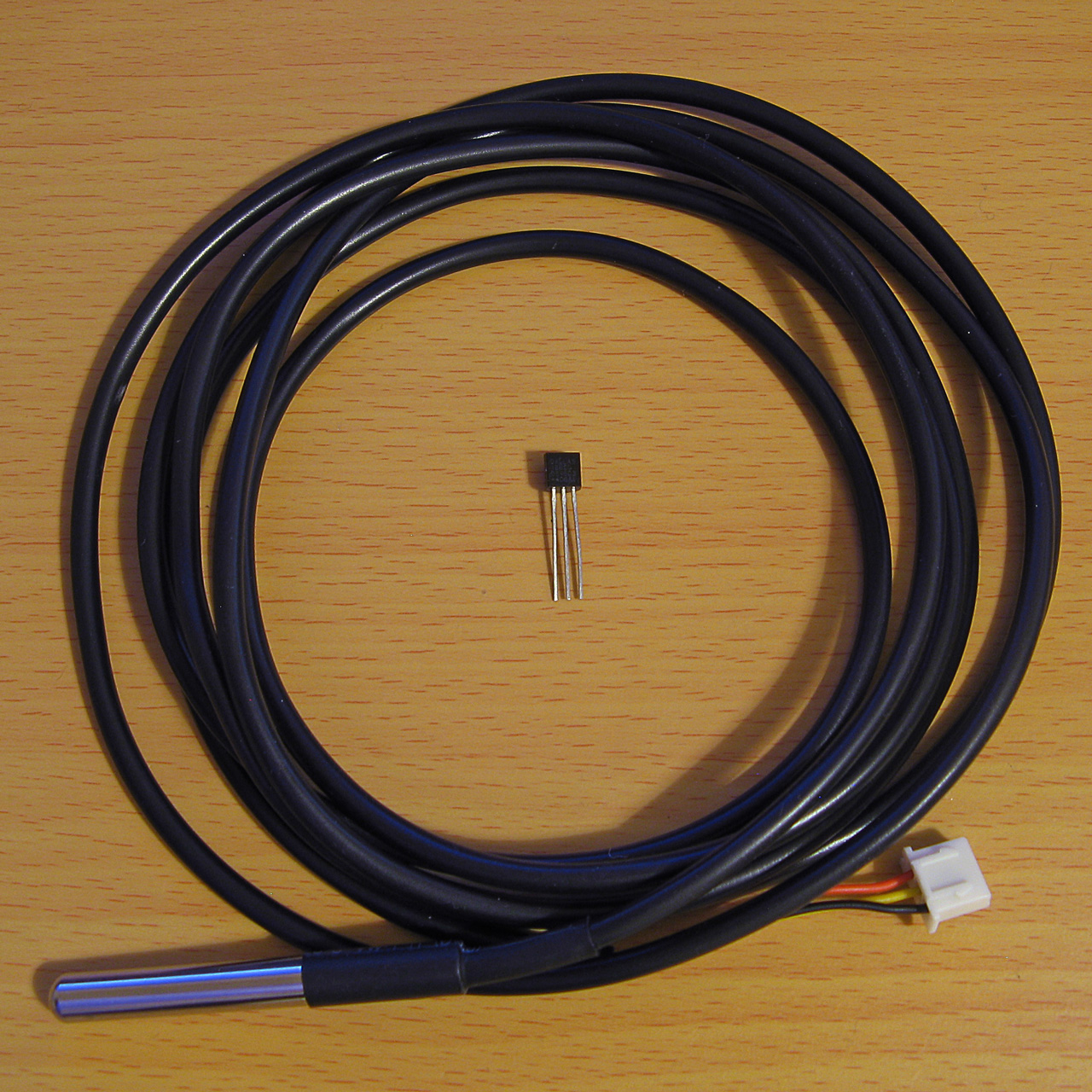
A DS18B20 temperature sensor in a TO-92 package and another in a cabled probe
The idea here will be to search for all temperature sensors on the network and to display their current temperature reading alongside their ID on the screen. The temperature conversion is initiated by sending the "Convert T" command (&44) to the desired 1-Wire devices and then waiting for at least 750ms with the bus inactive, allowing the parasitically-powered devices enough power to complete the temperature conversion, after which the temperature can be read back from the sensor's scratchpad memory.
Due to the large delay when waiting for the sensors to handle the "Convert T" command it is easiest to send the command to all devices on the network rather than to each one individually. This can be done by first sending the "Skip ROM" command (&CC) which allows the master to skip sending a 64-bit ID to the specific device it's addressing before sending the "Convert T" command (&44). The process to tell all devices to perform a temperature conversion is as follows:
IF FN_1W_RESET=FALSE PRINT "No devices found":END
REM Start temperature conversion
PROC_1W_PUT(&CC):REM Skip ROM
PROC_1W_PUT(&44):REM Convert T
T=TIME:IF INKEY(75)>TRUE REPEAT:UNTIL TIME>T+75:REM Delay 750ms
INKEY(75) is used to delay for 750ms however as this can be skipped by pressing a key a delay loop is provided as a safety measure.
After this, all of the devices on the network are enumerated as before:
REM Search for all temperature sensors on the bus and display their readings
PROC_1W_SEARCH_RESET
REPEAT F%=FN_1W_SEARCH(&F0,ID)
  IF F% PROC_1W_PRINT_TEMP(ID)
UNTIL F%=FALSE
PROC_1W_PRINT_TEMP should check to see whether the device ID corresponds to a temperature sensor (its family code, the least-significant byte, should be &28) and if so it should retrieve the temperature value and print it:
REM Print a single sensor's reading
DEFPROC_1W_PRINT_TEMP(ID)
LOCAL T
IF ID?0<>&28 ENDPROC:REM Must be a temperature sensor
T=FN_1W_READ_TEMP(ID):IF T=-999 ENDPROC:REM Read sensor and check for error
@%=&20409:PRINT MID$(FN_1W_ID$(ID),3,12);":",T;" deg C":@%=&90A
ENDPROC
@% controls the way numbers are printed – in this case it is changed to show four decimal places in a field width of 9 characters. When printing the device ID the first two characters and last two characters are stripped off as these correspond to the CRC and family code which are not particularly useful in this case.
FN_1W_READ_TEMP(ID) needs to fetch the temperature from the sensor with the specified ID or return -999 on error. A specific sensor can be addressed by first sending the match ROM command (&55) followed by the 64-bit device ID. After this the scratchpad RAM can be read by sending the "read scratchpad" command (&BE) then reading as many bytes as are required. We only need the first two, but will read nine as this includes all eight bytes of scratchpad RAM plus a CRC so we can verify the data is valid:
REM Retrieve a single sensor's reading
DEFFN_1W_READ_TEMP(ID)
LOCAL T
IF FN_1W_RESET=FALSE =-999
PROC_1W_PUT(&55):PROC_1W_PUTS(ID,8):REM Match ROM
PROC_1W_PUT(&BE):PROC_1W_GETS(SCRATCH,9):REM Read scratchpad
IF FN_1W_CRC_CHECK(SCRATCH,8)=FALSE =-999:REM Check CRC
=SCRATCH!-2DIV65536/16:REM Convert to degrees C
The final line converts the reading to °C. This is a signed 16-bit value stored in the first two bytes of the scratchpad memory. BBC BASIC's ! indirection operator reads a 32-bit value, so by reading from two bytes earlier (-2) the 16-bit temperature value is loaded into the most significant word of a 32-bit integer, and an integer divide of this by 65536 shifts this back down into the least significant word (where it should be) with the sign properly extended (so if it was a negative value before it will still be negative after the division). The value is then divided by 16 using a regular floating-point division as each unit of the temperature sensor's reported value corresponds to 1/16°C.
A complete demo program listing is shown below. Choosing option "3) Show DS18B20 temperatures" will show the temperatures of any connected DS18B20 temperature sensors.
  10 REM 1-WIRE DEMONSTRATION FOR Z88 : BEN RYVES 2023
  20 *NAME 1-Wire Demo
  30 DIM ID 7,SCRATCH 8
  40 PROC_1W_INIT
  50 :
  60 REM Main demo loop
  70 REPEAT PROC_1W_DEMO_MENU
  80   ON ERROR PRINT:END
  90   PRINT "<Press any key>";
 100   REPEAT UNTIL INKEY(0)=TRUE:IF GET
 110 UNTIL FALSE
 120 END
 130 :
 140 REM Main menu
 150 DEFPROC_1W_DEMO_MENU
 160 CLS:PRINT CHR$1;"1B";"1-Wire Demonstration for Cambridge Z88";CHR$1;"1B"
 170 ON ERROR END
 180 REPEAT
 190   PRINT '"Please choose a demo: (press ESC to exit)"
 200   PRINT "1) Enumerate devices"
 210   PRINT "2) Scan iButton tags"
 220   PRINT "3) Show DS18B20 temperatures"
 230   M%=GET-ASC"0"
 240 UNTIL M%>0 AND M%<4
 250 ON ERROR OFF
 260 PRINT
 270 ON M% PROC_1W_DEMO_LIST_DEVICES, PROC_1W_DEMO_TAG, PROC_1W_DEMO_SHOW_TEMPERATURES
 280 ENDPROC
 290 END
 300 :
 310 REM Device search demo
 320 DEFPROC_1W_DEMO_LIST_DEVICES
 330 PROC_1W_SEARCH_RESET
 340 REPEAT F%=FN_1W_SEARCH(&F0,ID):IF F% PRINT FN_1W_ID$(ID)
 350 UNTIL F%=FALSE:ENDPROC
 360 :
 370 REM ID tag scanning demo
 380 DEFPROC_1W_DEMO_TAG
 390 ON ERROR GOTO 50
 400 PRINT "Tap a tag on the reader (press ESC to exit)"
 410 REPEAT
 420   REPEAT UNTIL FN_1W_RESET:REM Wait for device to be present
 430   PROC_1W_PUT(&33):REM Read ROM
 440   PROC_1W_GETS(ID,8):REM Fetch ID
 450   IF FN_1W_CRC_CHECK(ID,7) AND ID?0=1 VDU 7:PRINT "Detected ";FN_1W_ID$(ID);" at ";TIME$:REM Print if valid
 460   REPEAT UNTIL FN_1W_RESET=FALSE:REM Wait for device to be disconnected
 470 UNTIL FALSE
 480 ENDPROC
 490 :
 500 REM Temperature demo
 510 DEFPROC_1W_DEMO_SHOW_TEMPERATURES
 520 IF FN_1W_RESET=FALSE PRINT "No devices found":ENDPROC
 530 REM Start temperature conversion
 540 PROC_1W_PUT(&CC):REM Skip ROM
 550 PROC_1W_PUT(&44):REM Convert T
 560 T=TIME:IF INKEY(75)>TRUE REPEAT:UNTIL TIME>T+75:REM Delay 750ms
 570 REM Search for all temperature sensors on the bus and display their readings
 580 PROC_1W_SEARCH_RESET
 590 REPEAT F%=FN_1W_SEARCH(&F0,ID)
 600   IF F% PROC_1W_PRINT_TEMP(ID)
 610 UNTIL F%=FALSE
 620 ENDPROC
 630 REM Print a single sensor's reading
 640 DEFPROC_1W_PRINT_TEMP(ID)
 650 LOCAL T
 660 IF ID?0<>&28 ENDPROC:REM Must be a temperature sensor
 670 T=FN_1W_READ_TEMP(ID):IF T=-999 ENDPROC:REM Read sensor and check for error
 680 @%=&20409:PRINT MID$(FN_1W_ID$(ID),3,12);":",T;" deg C":@%=&90A
 690 ENDPROC
 700 REM Retrieve a single sensor's reading
 710 DEFFN_1W_READ_TEMP(ID)
 720 LOCAL T
 730 IF FN_1W_RESET=FALSE =-999
 740 PROC_1W_PUT(&55):PROC_1W_PUTS(ID,8):REM Match ROM
 750 PROC_1W_PUT(&BE):PROC_1W_GETS(SCRATCH,9):REM Read scratchpad
 760 IF FN_1W_CRC_CHECK(SCRATCH,8)=FALSE =-999:REM Check CRC
 770 =SCRATCH!-2DIV65536/16:REM Convert to degrees C
 780 :
 790 REM 1-WIRE ROUTINES
 800 END
 810 DEFPROC_1W_INIT
 820 ow_code_size=294:DIM ow_code ow_code_size-1
 830 RXE=&E1:M_RXERXD=&10
 840 TXC=&E4:M_TXCITX=&08
 850 SC=&400
 860 FOR opt=0 TO 2 STEP 2
 870   P%=ow_code
 880   [OPT opt
 890   .ow_buf DEFB 0 \ temporary transfer buffer
 900   .ow_conf DEFB 0 \ stores last bit conflict index
 910   :
 920   .ow_reset
 930   IN A,(RXE):AND M_RXERXD:CP M_RXERXD:SBC A,A:LD (ow_buf),A:RET NZ \ check bus is idle
 940   DI:LD A,(SC+TXC):OR M_TXCITX:OUT (TXC),A \ hold bus low
 950   LD B,120:DJNZ P% \ delay
 960   AND NOT M_TXCITX:OUT (TXC),A \ release bus
 970   LD B,18:DJNZ P% \ delay
 980   IN A,(RXE):AND M_RXERXD:CP M_RXERXD:CCF:SBC A,A:LD (ow_buf),A \ sample presence
 990   LD B,100:DJNZ P% \ delay
1000   EI:RET
1010   :
1020   .ow_put_carry
1030   JR C,ow_put_1 \ fall-through
1040   :
1050   .ow_put_0
1060   DI
1070   LD A,(SC+TXC):OR M_TXCITX:OUT (TXC),A \ hold bus low
1080   LD B,15:DJNZ P% \ delay
1090   AND NOT M_TXCITX:OUT (TXC),A \ release bus
1100   NOP \ delay
1110   EI:RET
1120   :
1130   .ow_put_1
1140   DI
1150   LD A,(SC+TXC):OR M_TXCITX:OUT (TXC),A \ hold bus low
1160   NOP \ delay
1170   AND NOT M_TXCITX:OUT (TXC),A \ release bus
1180   PUSH HL:POP HL \ delay
1190   IN A,(RXE):AND M_RXERXD:SUB M_RXERXD:CCF \ sample bit
1200   LD A,(ow_buf):RRA:LD (ow_buf),A \ store bit
1210   LD B,7:DJNZ P% \ delay
1220   EI:RET
1230   :
1240   .ow_put_byte
1250   LD C,A:LD B,8 \ value to send in C, send 8 bits
1260   .ow_put_loop
1270   SRL C:PUSH BC:CALL ow_put_carry:POP BC \ shift and send single bit
1280   DJNZ ow_put_loop \ loop
1290   RET
1300   :
1310   .ow_put_bytes
1320   LD A,B:OR C:RET Z:DEC BC \ have we finished?
1330   LD A,(HL):INC HL \ fetch
1340   PUSH BC:CALL ow_put_byte:POP BC:JR ow_put_bytes \ send and loop
1350   :
1360   .ow_get_byte
1370   LD B,8 \ 8 bits to receive
1380   .ow_get_loop
1390   PUSH BC:CALL ow_put_1:POP BC \ receive single bit
1400   DJNZ ow_get_loop \ loop
1410   LD A,(ow_buf):RET \ store
1420   :
1430   .ow_get_bytes
1440   LD A,B:OR C:RET Z:DEC BC \ have we finished?
1450   PUSH BC:CALL ow_get_byte:POP BC \ get a byte
1460   LD (HL),A:INC HL:JR ow_get_bytes \ store and loop
1470   :
1480   .ow_search
1490   LD DE,(ow_conf):LD D,0:LD C,1:LD B,64
1500   .ow_search_loop
1510   PUSH BC:CALL ow_put_1:CALL ow_put_1:POP BC:RLCA:RLCA \ get bit, !bit
1520   AND 3:JR Z,ow_search_conf \ 00 = conflict
1530   DEC A:JR Z,ow_search_1 \ 01 = 0 bit
1540   DEC A:JR Z,ow_search_0 \ 10 =  1 bit
1550   SCF:RET \ report failure
1560   .ow_search_conf
1570   LD A,B:CP E \ how does bit index compare to last conflict
1580   JR C,ow_search_0_conf \ 0, update current discrepancy
1590   JR Z,ow_search_1 \ 1, no update
1600   LD A,(HL):AND C:JR NZ,ow_search_advance \ old bit = 1, just advance
1610   LD D,B:JR ow_search_advance \ old bit = 0, update current discrepancy
1620   .ow_search_1:LD A,C:OR (HL):LD (HL),A:JR ow_search_advance
1630   .ow_search_0_conf:LD D,B \ fall-through
1640   .ow_search_0:LD A,C:CPL:AND (HL):LD (HL),A \ fall-through
1650   .ow_search_advance
1660   LD A,(HL):AND C:SUB C:CCF:PUSH BC:CALL ow_put_carry:POP BC \ return the ID bit
1670   RLC C:JR NC,P%+3:INC HL \ advance mask
1680   DJNZ ow_search_loop
1690   LD A,D:LD (ow_conf),A
1700   XOR A:LD (ow_buf),A:RET \ report success
1710   :
1720   .ow_crc
1730   LD B,8:LD DE,(ow_buf):LD D,A \ E = accumulated CRC, D = value to add
1740   .ow_crc_loop
1750   LD A,E:XOR D:SRL D:SRL A:JR C,ow_crc_odd \ XOR and shift bits
1760   SRL E:DJNZ ow_crc_loop:LD A,E:LD (ow_buf),A:RET \ even CRC value
1770   .ow_crc_odd:SRL E:LD A,&8C:XOR E:LD E,A:DJNZ ow_crc_loop:LD (ow_buf),A:RET \ odd CRC value
1780   :
1790   .ow_crc_block
1800   XOR A:LD (ow_buf),A \ reset CRC
1810   .ow_crc_block_loop
1820   LD A,B:OR C:LD A,(ow_buf):RET Z:DEC BC \ have we finished?
1830   LD A,(HL):INC HL:PUSH BC:CALL ow_crc:POP BC:JR ow_crc_block_loop \ update CRC
1840   ]
1850 NEXT
1860 IF P%-ow_code<>ow_code_size PRINT"Code size: "P%-ow_code:END
1870 ENDPROC
1880 :
1890 REM Resets bus, retuns TRUE if any devices are present
1900 DEFFN_1W_RESET:CALL ow_reset:=?ow_buf=0
1910 REM Transmits a single byte
1920 DEFPROC_1W_PUT(A%)CALL ow_put_byte:ENDPROC
1930 REM Transmits a block of bytes
1940 DEFPROC_1W_PUTS(L%,C%)LOCAL H%,B%:H%=L%DIV256:B%=C%DIV256:CALL ow_put_bytes:ENDPROC
1950 REM Receives a single byte
1960 DEFFN_1W_GET:CALL ow_get_byte:=?ow_buf
1970 REM Receives a block of bytes
1980 DEFPROC_1W_GETS(L%,C%)LOCAL H%,B%:H%=L%DIV256:B%=C%DIV256:CALL ow_get_bytes:ENDPROC
1990 :
2000 REM Starts enumerating devices on the bus
2010 DEFPROC_1W_SEARCH_RESET:?ow_conf=TRUE:ENDPROC
2020 REM Searches for next device on bus. Pass search type &F0 for all devices, &EC for alarming devices. Returns TRUE if next device found
2030 DEFFN_1W_SEARCH(A%,ID)IF ?ow_conf=0:=FALSE ELSE IF FN_1W_RESET=0:=FALSE ELSE PROC_1W_PUT(A%):H%=ID DIV256:L%=ID:CALL ow_search:=?ow_buf=0
2040 :
2050 REM Converts ID bytes into string
2060 DEFFN_1W_ID$(ID)LOCAL I%:S$="":FOR I%=7 TO 0 STEP -1:IF ID?I%>15:S$=S$+STR$~(ID?I%):NEXT:=S$:ELSE:S$=S$+"0"+STR$~(ID?I%):NEXT:=S$
2070 REM Converts string into ID bytes
2080 DEFPROC_1W_ID$(ID,ID$)LOCAL I%:FOR I%=0 TO 7:ID?I%=EVAL("&"+MID$(ID$,15-I%*2,2)):NEXT:ENDPROC
2090 :
2100 REM Calculates the CRC of a block of data
2110 DEFFN_1W_CRC(L%,C%)LOCAL H%,B%:H%=L% DIV256:B%=C%DIV256:CALL ow_crc_block:=?ow_buf
2120 REM Checks if a CRC at the end of a block of data matches
2130 DEFFN_1W_CRC_CHECK(L%,C%)=FN_1W_CRC(L%,C%)=(L%?C%)
Temperature logger
All of this can be put together into a program that logs the temperature from any connected sensors to a CSV file on the Z88. The main loop can look similar to the one above that searches for and displays the temperature readings for any connected DS18B20 sensors, however it will instead call a PROC_1W_LOG_TEMP procedure that handles logging the data to a file instead of printing it on the display:
REM Log a single sensor's reading
DEFPROC_1W_LOG_TEMP(ID)
LOCAL T
IF ID?0<>&28 ENDPROC:REM Must be a temperature sensor
T=FN_1W_READ_TEMP(ID):IF T=-999 ENDPROC:REM Read sensor and check for error
ENTRY$=FN_DATETIME$(TIME$)+","+STR$T:REM Timestamp and temperature reading
ID$=MID$(FN_1W_ID$(ID),3,12):REM ID without CRC and family code
CSV$=ID$+".CSV":REM Name of CSV file
C=OPENUP CSV$:REM Open the CSV for update
IF C=FALSE C=OPENOUT CSV$:PRINT#C,"Time,"+ID$:REM Create new CSV if required
PTR#C=EXT#C:PRINT#C,ENTRY$:REM Write entry to end of CSV
CLOSE#C:REM Close the CSV
PRINT CSV$,ENTRY$:REM Display on screen
ENDPROC
The procedure will fetch the value from the sensor and then turn the ID into a CSV filename by stripping off the CRC and family code and appending ".CSV". It will then try to open the existing file, and if one doesn't exist it will create a new one and write the column headers to it. It will then seek to the end of the file and append the timestamp and the temperature reading.
One further complication is that to make handling the CSV a bit easier, the timestamp is converted from the format returned by BBC BASIC's TIME$ function into "YYYY-MM-DD hh:mm:ss" format. This is handled by the following three functions, FN_DATE (which extracts and reformats the date component into YYYY-MM-DD format), FN_TIME (which extracts the time component into hh:mm:ss format) and FN_DATETIME which glues the date and time back together with a space in the middle:
REM Date formatting routines
DEF FN_DATE$(T$)
LOCAL C%,I%,J%,V%,R$
R$="":I%=1
FOR C%=0 TO 3 J%=INSTR(MID$(T$,I%)," ")
  IF C%=2 V%=1+INSTR("JanFebMarAprMayJunJulAugSepOctNovDec",MID$(T$,I%,3))DIV3 ELSE V%=VAL(MID$(T$,I%,J%-1))
  IF C%>1 R$="-"+R$
  IF C% R$=STR$(V%)+R$ IF V%<10 R$="0"+R$
  I%=I%+J%
NEXT
=R$
DEF FN_TIME$(T$) =MID$(T$,LEN(T$)-7)
DEF FN_DATETIME$(T$) =FN_DATE$(T$)+" "+FN_TIME$(T$)
One way to make this logging program more useful would be to get the computer to run it periodically (e.g. once per minute). The Z88's "Alarm" feature can execute a command whenever the alarm goes off and you can schedule recurring alarms so this sounds like an ideal starting point! When the program has run it would also be handy for the computer to switch itself off again. There is an OS call for this, OS_Off, which can be invoked from BASIC as follows:
REM SWITCH OFF ROUTINES
DEFPROC_SWITCH_OFF_INIT
switch_off_size=15:DIM switch_off switch_off_size-1
P%=switch_off
[OPT 2
LD HL,0:ADD HL,SP:LD SP,(&1FFE):PUSH HL
RST &20:DEFW &EC06:REM OS_Off
POP HL:LD SP,HL:RET:]
ENDPROC
DEFPROC_SWITCH_OFF:CALL switch_off:ENDPROC
As with the 1-Wire assembly routines you must first call an initialisation procedure (PROC_SWITCH_OFF_INIT) to assemble the routine before calling it with PROC_SWITCH_OFF. The actual OS_Off call is the RST &20H:DEFW &EC06 in the middle of all that. Unfortunately, OS calls tend to involve some memory paging and in the process BBC BASIC's RAM gets swapped out and when the OS routine tries to return it jumps back into some different memory – the computer certainly switches off, but then it soft resets instead of coming back on properly. This is why there's some additional boilerplate code around the OS call to move the stack pointer into a safe region of memory so the routine can return properly.
The complete temperature-logging program is now shown below:
  10 REM 1-WIRE TEMPERATURE LOGGER : BEN RYVES 2023
  20 *NAME 1-Wire Temperature Logger
  30 REPEAT UNTIL INKEY(0)=TRUE:REM Flush keyboard
  40 DIM ID 7,SCRATCH 8
  50 PROC_1W_INIT
  60 PROC_SWITCH_OFF_INIT
  70 REM Reset 1-Wire bus and check that at least one device is present
  80 IF FN_1W_RESET=FALSE PROC_SWITCH_OFF:END
  90 REM Start temperature conversion
 100 PROC_1W_PUT(&CC):REM Skip ROM
 110 PROC_1W_PUT(&44):REM Convert T
 120 T=TIME:IF INKEY(75)>TRUE REPEAT:UNTIL TIME>T+75:REM Delay 750ms
 130 REM Search for all temperature sensors on the bus and log their readings
 140 PROC_1W_SEARCH_RESET
 150 REPEAT F%=FN_1W_SEARCH(&F0,ID):IF F% PROC_1W_LOG_TEMP(ID)
 160 UNTIL F%=FALSE
 170 REM Switch the computer off
 180 PROC_SWITCH_OFF
 190 END
 200 :
 210 REM Log a single sensor's reading
 220 DEFPROC_1W_LOG_TEMP(ID)
 230 LOCAL T
 240 IF ID?0<>&28 ENDPROC:REM Must be a temperature sensor
 250 T=FN_1W_READ_TEMP(ID):IF T=-999 ENDPROC:REM Read sensor and check for error
 260 ENTRY$=FN_DATETIME$(TIME$)+","+STR$T:REM Timestamp and temperature reading
 270 ID$=MID$(FN_1W_ID$(ID),3,12):REM ID without CRC and family code
 280 CSV$=ID$+".CSV":REM Name of CSV file
 290 C=OPENUP CSV$:REM Open the CSV for update
 300 IF C=FALSE C=OPENOUT CSV$:PRINT#C,"Time,"+ID$:REM Create new CSV if required
 310 PTR#C=EXT#C:PRINT#C,ENTRY$:REM Write entry to end of CSV
 320 CLOSE#C:REM Close the CSV
 330 PRINT CSV$,ENTRY$:REM Display on screen
 340 ENDPROC
 350 REM Retrieve a single sensor's reading
 360 DEFFN_1W_READ_TEMP(ID)
 370 LOCAL T
 380 IF FN_1W_RESET=FALSE =-999
 390 PROC_1W_PUT(&55):PROC_1W_PUTS(ID,8):REM Match ROM
 400 PROC_1W_PUT(&BE):PROC_1W_GETS(SCRATCH,9):REM Read scratchpad
 410 IF FN_1W_CRC_CHECK(SCRATCH,8)=FALSE =-999:REM Check CRC
 420 =SCRATCH!-2DIV65536/16:REM Convert to degrees C
 430 :
 440 REM Date formatting routines
 450 DEF FN_DATE$(T$)
 460 LOCAL C%,I%,J%,V%,R$
 470 R$="":I%=1
 480 FOR C%=0 TO 3 J%=INSTR(MID$(T$,I%)," ")
 490   IF C%=2 V%=1+INSTR("JanFebMarAprMayJunJulAugSepOctNovDec",MID$(T$,I%,3))DIV3 ELSE V%=VAL(MID$(T$,I%,J%-1))
 500   IF C%>1 R$="-"+R$
 510   IF C% R$=STR$(V%)+R$ IF V%<10 R$="0"+R$
 520   I%=I%+J%
 530 NEXT
 540 =R$
 550 DEF FN_TIME$(T$) =MID$(T$,LEN(T$)-7)
 560 DEF FN_DATETIME$(T$) =FN_DATE$(T$)+" "+FN_TIME$(T$)
 570 :
 580 REM SWITCH OFF ROUTINES
 590 DEFPROC_SWITCH_OFF_INIT
 600 switch_off_size=15:DIM switch_off switch_off_size-1
 610 P%=switch_off
 620 [OPT 2
 630 LD HL,0:ADD HL,SP:LD SP,(&1FFE):PUSH HL
 640 RST &20:DEFW &EC06
 650 POP HL:LD SP,HL:RET:]
 660 ENDPROC
 670 DEFPROC_SWITCH_OFF:CALL switch_off:ENDPROC
 680 :
 690 REM 1-WIRE ROUTINES
 700 END
 710 DEFPROC_1W_INIT
 720 ow_code_size=294:DIM ow_code ow_code_size-1
 730 RXE=&E1:M_RXERXD=&10
 740 TXC=&E4:M_TXCITX=&08
 750 SC=&400
 760 FOR opt=0 TO 2 STEP 2
 770   P%=ow_code
 780   [OPT opt
 790   .ow_buf DEFB 0 \ temporary transfer buffer
 800   .ow_conf DEFB 0 \ stores last bit conflict index
 810   :
 820   .ow_reset
 830   IN A,(RXE):AND M_RXERXD:CP M_RXERXD:SBC A,A:LD (ow_buf),A:RET NZ \ check bus is idle
 840   DI:LD A,(SC+TXC):OR M_TXCITX:OUT (TXC),A \ hold bus low
 850   LD B,120:DJNZ P% \ delay
 860   AND NOT M_TXCITX:OUT (TXC),A \ release bus
 870   LD B,18:DJNZ P% \ delay
 880   IN A,(RXE):AND M_RXERXD:CP M_RXERXD:CCF:SBC A,A:LD (ow_buf),A \ sample presence
 890   LD B,100:DJNZ P% \ delay
 900   EI:RET
 910   :
 920   .ow_put_carry
 930   JR C,ow_put_1 \ fall-through
 940   :
 950   .ow_put_0
 960   DI
 970   LD A,(SC+TXC):OR M_TXCITX:OUT (TXC),A \ hold bus low
 980   LD B,15:DJNZ P% \ delay
 990   AND NOT M_TXCITX:OUT (TXC),A \ release bus
1000   NOP \ delay
1010   EI:RET
1020   :
1030   .ow_put_1
1040   DI
1050   LD A,(SC+TXC):OR M_TXCITX:OUT (TXC),A \ hold bus low
1060   NOP \ delay
1070   AND NOT M_TXCITX:OUT (TXC),A \ release bus
1080   PUSH HL:POP HL \ delay
1090   IN A,(RXE):AND M_RXERXD:SUB M_RXERXD:CCF \ sample bit
1100   LD A,(ow_buf):RRA:LD (ow_buf),A \ store bit
1110   LD B,7:DJNZ P% \ delay
1120   EI:RET
1130   :
1140   .ow_put_byte
1150   LD C,A:LD B,8 \ value to send in C, send 8 bits
1160   .ow_put_loop
1170   SRL C:PUSH BC:CALL ow_put_carry:POP BC \ shift and send single bit
1180   DJNZ ow_put_loop \ loop
1190   RET
1200   :
1210   .ow_put_bytes
1220   LD A,B:OR C:RET Z:DEC BC \ have we finished?
1230   LD A,(HL):INC HL \ fetch
1240   PUSH BC:CALL ow_put_byte:POP BC:JR ow_put_bytes \ send and loop
1250   :
1260   .ow_get_byte
1270   LD B,8 \ 8 bits to receive
1280   .ow_get_loop
1290   PUSH BC:CALL ow_put_1:POP BC \ receive single bit
1300   DJNZ ow_get_loop \ loop
1310   LD A,(ow_buf):RET \ store
1320   :
1330   .ow_get_bytes
1340   LD A,B:OR C:RET Z:DEC BC \ have we finished?
1350   PUSH BC:CALL ow_get_byte:POP BC \ get a byte
1360   LD (HL),A:INC HL:JR ow_get_bytes \ store and loop
1370   :
1380   .ow_search
1390   LD DE,(ow_conf):LD D,0:LD C,1:LD B,64
1400   .ow_search_loop
1410   PUSH BC:CALL ow_put_1:CALL ow_put_1:POP BC:RLCA:RLCA \ get bit, !bit
1420   AND 3:JR Z,ow_search_conf \ 00 = conflict
1430   DEC A:JR Z,ow_search_1 \ 01 = 0 bit
1440   DEC A:JR Z,ow_search_0 \ 10 =  1 bit
1450   SCF:RET \ report failure
1460   .ow_search_conf
1470   LD A,B:CP E \ how does bit index compare to last conflict
1480   JR C,ow_search_0_conf \ 0, update current discrepancy
1490   JR Z,ow_search_1 \ 1, no update
1500   LD A,(HL):AND C:JR NZ,ow_search_advance \ old bit = 1, just advance
1510   LD D,B:JR ow_search_advance \ old bit = 0, update current discrepancy
1520   .ow_search_1:LD A,C:OR (HL):LD (HL),A:JR ow_search_advance
1530   .ow_search_0_conf:LD D,B \ fall-through
1540   .ow_search_0:LD A,C:CPL:AND (HL):LD (HL),A \ fall-through
1550   .ow_search_advance
1560   LD A,(HL):AND C:SUB C:CCF:PUSH BC:CALL ow_put_carry:POP BC \ return the ID bit
1570   RLC C:JR NC,P%+3:INC HL \ advance mask
1580   DJNZ ow_search_loop
1590   LD A,D:LD (ow_conf),A
1600   XOR A:LD (ow_buf),A:RET \ report success
1610   :
1620   .ow_crc
1630   LD B,8:LD DE,(ow_buf):LD D,A \ E = accumulated CRC, D = value to add
1640   .ow_crc_loop
1650   LD A,E:XOR D:SRL D:SRL A:JR C,ow_crc_odd \ XOR and shift bits
1660   SRL E:DJNZ ow_crc_loop:LD A,E:LD (ow_buf),A:RET \ even CRC value
1670   .ow_crc_odd:SRL E:LD A,&8C:XOR E:LD E,A:DJNZ ow_crc_loop:LD (ow_buf),A:RET \ odd CRC value
1680   :
1690   .ow_crc_block
1700   XOR A:LD (ow_buf),A \ reset CRC
1710   .ow_crc_block_loop
1720   LD A,B:OR C:LD A,(ow_buf):RET Z:DEC BC \ have we finished?
1730   LD A,(HL):INC HL:PUSH BC:CALL ow_crc:POP BC:JR ow_crc_block_loop \ update CRC
1740   ]
1750 NEXT
1760 IF P%-ow_code<>ow_code_size PRINT"Code size: "P%-ow_code:END
1770 ENDPROC
1780 :
1790 REM Resets bus, retuns TRUE if any devices are present
1800 DEFFN_1W_RESET:CALL ow_reset:=?ow_buf=0
1810 REM Transmits a single byte
1820 DEFPROC_1W_PUT(A%)CALL ow_put_byte:ENDPROC
1830 REM Transmits a block of bytes
1840 DEFPROC_1W_PUTS(L%,C%)LOCAL H%,B%:H%=L%DIV256:B%=C%DIV256:CALL ow_put_bytes:ENDPROC
1850 REM Receives a single byte
1860 DEFFN_1W_GET:CALL ow_get_byte:=?ow_buf
1870 REM Receives a block of bytes
1880 DEFPROC_1W_GETS(L%,C%)LOCAL H%,B%:H%=L%DIV256:B%=C%DIV256:CALL ow_get_bytes:ENDPROC
1890 :
1900 REM Starts enumerating devices on the bus
1910 DEFPROC_1W_SEARCH_RESET:?ow_conf=TRUE:ENDPROC
1920 REM Searches for next device on bus. Pass search type &F0 for all devices, &EC for alarming devices. Returns TRUE if next device found
1930 DEFFN_1W_SEARCH(A%,ID)IF ?ow_conf=0:=FALSE ELSE IF FN_1W_RESET=0:=FALSE ELSE PROC_1W_PUT(A%):H%=ID DIV256:L%=ID:CALL ow_search:=?ow_buf=0
1940 :
1950 REM Converts ID bytes into string
1960 DEFFN_1W_ID$(ID)LOCAL I%:S$="":FOR I%=7 TO 0 STEP -1:IF ID?I%>15:S$=S$+STR$~(ID?I%):NEXT:=S$:ELSE:S$=S$+"0"+STR$~(ID?I%):NEXT:=S$
1970 REM Converts string into ID bytes
1980 DEFPROC_1W_ID$(ID,ID$)LOCAL I%:FOR I%=0 TO 7:ID?I%=EVAL("&"+MID$(ID$,15-I%*2,2)):NEXT:ENDPROC
1990 :
2000 REM Calculates the CRC of a block of data
2010 DEFFN_1W_CRC(L%,C%)LOCAL H%,B%:H%=L% DIV256:B%=C%DIV256:CALL ow_crc_block:=?ow_buf
2020 REM Checks if a CRC at the end of a block of data matches
2030 DEFFN_1W_CRC_CHECK(L%,C%)=FN_1W_CRC(L%,C%)=(L%?C%)
When run this will log the temperatures of all connected sensors to CSV files as described above then switch the Z88 off. The "Alarm" popdown can be used to set up an alarm that runs the program once per minute (or at any other desired interval) by choosing an alarm type of "execute". This will effectively type in the supplied command, and so by setting it to #BRUN"TEMPLOG.BBC"~E it will press □+B to switch to BASIC (#B), type in RUN"TEMPLOG" and then press Enter (~E).

Setting up the alarm this way each time can be a bit tedious, so to make things easier here's a CLI file that can be used to set up the alarm:
.;Set up temperature logging alarm
#A
~R~E
~D~D
##BRUN"TEMPLOG.BBC"~~E
~D
~D~R~D~R~S~U~S~U~R~D
This contains keystrokes in a similar fashion to the "command" field in the alarm settings and can be "executed" from the Z88's Filer; here #A presses □+A to enter the Alarm pop-down, ~R, ~D or ~U move the cursor right, down or up and where we need to type literal # or ~ signs they are doubled up (## or ~~). This will enter all of the required details to set up an alarm that will run the task once per minute forever, at which point they can be adjusted if required (e.g. to change the interval). Pressing Enter will create the alarm, and leaving the Alarm popdown will set it in motion. To finish data collection the Z88 can be switched back on as normal for the alarm to be cleared.
The only other point of note is that I found that the computer seemed to get a bit "gummed up" with queued keypresses. This could be because it never sits idle after handling the alarm; it runs the BASIC program then switches the computer off, waiting for the next alarm to be run. This is why a simple loop to flush the keyboard buffer occurs at the start of the program, and the computer seems much happier for it.
The temperature logs in the CSV files can be used to generate a chart like the following:
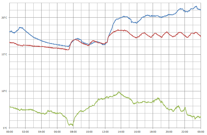
I captured data from three sensors over a 24 hour period; one outside (green line), one in my bedroom (red line) and one in my office (blue line). You can see how the central heating kicks in at 07:30, and I turned it up a little after 12:00. During the day the temperature in the bedroom moves up and down as the heating switches on and off, but the temperature in the office appears to be more consistent and a bit higher – the sensor is near where I am sitting and my desktop computer, which is likely contributing some heat.
Conclusion
What was originally intended to be a quick project to make use a couple of electronic components I had been sent in error soon turned into what I thought was an interesting demonstration of what can be done with the Cambridge Z88 using its stock software and some very basic additional hardware, further cementing my appreciation for the well-designed device.
The files accompanying this post can be downloaded below:
- ONEWIRE.BBC – 1-Wire demonstration program.
- TEMPLOG.BBC and TEMPLOG.CLI – Temperature logging program and CLI file to set up the alarm.
- templogs.zip and templogs.xlsx – Sample data captured by the temperature logging program.
Reverse engineering Z-Tape for the Cambridge Z88
Saturday, 10th June 2023
When reading about the Cambridge Z88 computer and its available software I bumped into the occasional mention of Z-Tape by Wordmongers, a system that allowed you to back up files from your Z88 to a cassette recorder. I had wondered how this worked, assuming there some sort of external hardware to connect the cassette recorder to the Z88 (likely via its serial port). I'd done some work on tape loading and saving myself for the Sega Master System and had come up with a somewhat hacky but minimal solution that relies on abuse of a hex inverter. Surely a commercially-released product would have a better way of doing things, or at least so I thought!
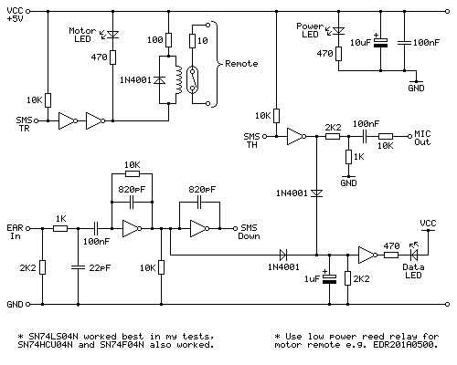
More recently I noticed someone had uploaded a copy of the application and some accompanying documentation to the Cambridge Z88 page on SourceForge, so I downloaded it to take a look and was very surprised at what I found:
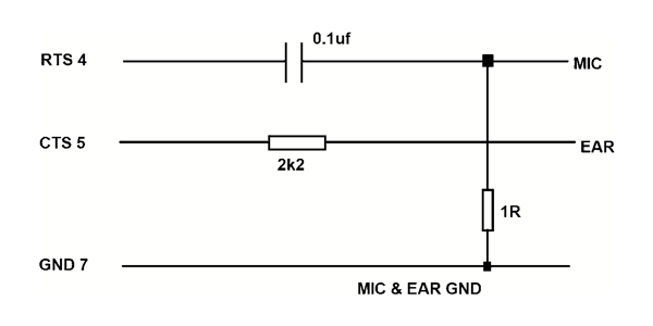
That can't work, surely? The output for recording seems sensible enough, using the 1Ω resistor to ground on the output to reduce the level down to something that could be fed into a sensitive microphone input, but just running the earphone output directly into the RS-232 port's CTS line doesn't seem like it would do the job. There's only one way to find out, though, and that's to build a cable and try it out and to my surprise it does indeed work!
I have had a few issues with this, however. The program appears to require that the phase of the data played back into the Z88 matches the phase that it was recorded. Both of my cassette recorders reverse the phase when playing back the recordings. Fortunately one of them does have a phase reversal switch, and two wrongs in this case does make a right and by setting the phase switch to "reverse" it allows Z-Tape to load back the recorded data.
The overall loader is not particularly reliable, though. It relies on a very strong output from the cassette recorder to successfully register a signal on the Z88's serial port, and I find I have to rewind to try again quite often. That it works at all with such a simple cable is certainly impressive, though.
In my testing I wrote a little BASIC program that crudely checks the signal level on the RS-232 input. You can use this to test the strength of your cassette recorder's output: it will display a rolling progress bar with the approximate signal strength. With my cassette recorder I can get over 80% when playing back a block, but I can't register anywhere near that when connecting the Z88 to my PC's audio output or my phone's headphone socket and consequently can't load back recordings from those devices.
10 *NAME Tape Level Test
20 REPEAT
30   S%=0
40   FORI%=0TO99:S%=S%+(GET(&E5)AND1):NEXT
50   S%=50-ABS(50-S%)
60   PRINT'S%*2;"% ";CHR$1;"R";CHR$1;"3N";CHR$(32+S%);" ";CHR$1;"G";CHR$1;"3N";CHR$(32+(50-S%));" ";CHR$1;"3-RG ";
70 UNTIL INKEY(0)<>-1
80 PRINT
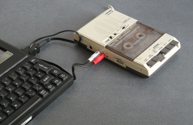
Once I'd experimented with Z-Tape and a cassette recorder I thought it would be interesting to see how it worked and whether I could reverse-engineer the format used. I connected the Z88 to my PC, made some recordings, and then set to work.
Bit-level format
The first thing to do is to establish the base frequency. After taking a recording from the Z88, I checked it in Audacity's frequency analyser and found a strong peak at 1590Hz:
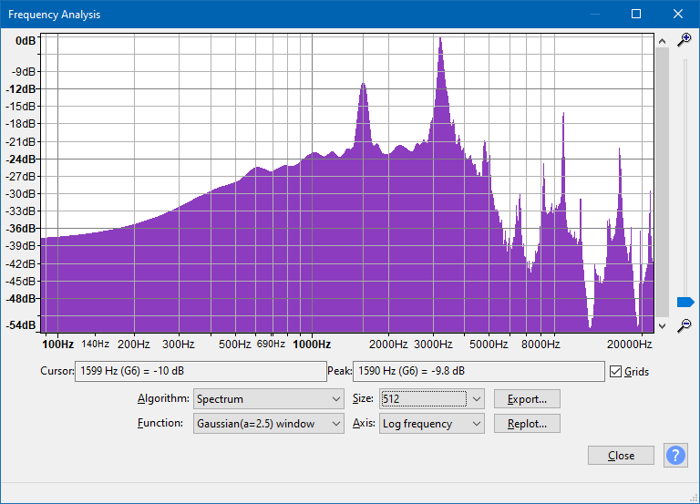
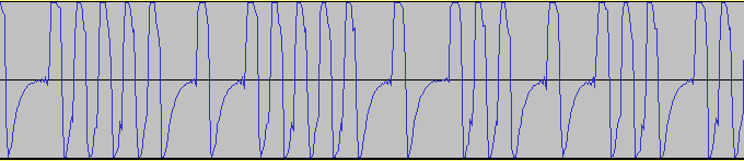
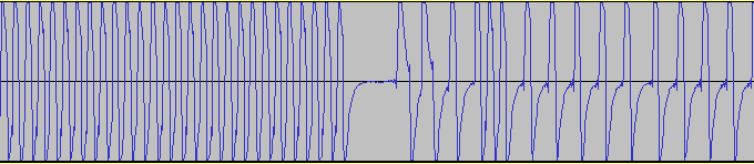
There is also a strong peak at 3195Hz, which is very close to twice the other peak's frequency (halving it gives us 1597.5Hz, close to 1590Hz). Based on these measurements it would seem that the base frequency is around 1600Hz, and likely that the tape format is a combination of 1600Hz and 3200Hz tones. Zooming into the recorded waveform shows the two different tones:
A common way to record data on tape is to use one full cycle of the base frequency to represent a "0" bit and two full cycles of twice the base frequency to represent a "1" bit. This means that the data is the same length regardless of how many "0"s or "1"s appear in the data, and looking at the length of data blocks in the recording they were all the same length, so it seems this is a possible candidate.
The phase of the signal is also important. If we represent the signal as a sine wave, a phase of 0° would start at zero, increase in the positive direction for the first quarter of the wave, head down in the negative direction for the next half of the wave, before returning to zero in a positive direction in the last quarter of the wave. Conversely a phase of 180° would start from zero but go negative in the first half of the wave before going positive in the second half of the wave. The phase can be determined by looking at the start of the signal after a period of silence:
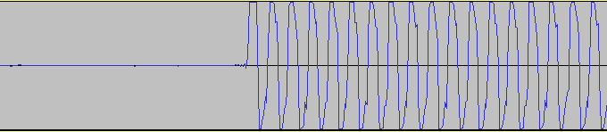
As the signal goes positive first after a period of silence we can confirm the signal has a phase of 0°. In summary, the bit-level format required by Z-Tape is as follows:
- Base frequency of 1600Hz.
- Phase of 0°.
- "0" bits encoded as one full cycle at base frequency (1600Hz).
- "1" bits encoded as two full cycles at twice the base frequency (3200Hz).
Block-level format
Now that we have a stream of bits, we can group them into blocks of data on the tape. Each block starts with a leader or pilot tone, which is effectively a long stream of "1" bits (3200Hz). This lasts 1.25 seconds, after which there is a very brief silence (around two full waves in length) followed by the stream of bits that make up the actual block data.
I created some files on the Z88 that followed certain obvious patterns, for example a file that alternated $00 bytes and $FF bytes so you'd expect to see eight consecutive "0" bits in the recording followed by eight consecutive "1" bits. This would help check to see if there were any start, stop or parity bits in the data (or if it was just eight plain bits of data). I also had a file that contained all of the numbers from $00 to $FF consecutively, so you'd be able to see a clear pattern of byte values counting up and use this to check whether the data was sent least-significant or most-significant bit first.
Using these files I quickly found that the data in each block always starts with two zero bits (immediately after the leader or pilot tone) and is then sent in plain 8-bit bytes (no start, stop or parity bits) with the least significant bit sent first. Each block always contains 1031 bytes of raw data, no matter the size of the file being transmitted. I knew that there was a checksum as Z-Tape would occasionally grumble when loading about a checksum error and I could see that after transferring small files there'd be data at the start of the block, a gap filled with zeroes, followed by a final non-zero data byte. I assumed this was the checksum, and found that by adding up all 1031 bytes in the block the result always came to zero. The checksum can therefore be calculated by setting a counter to zero, subtracting the value of every byte in the 1030 data bytes of the block, and then appending the counter value to as the 1031st byte of the block.
In summary, the block-level format is as follows:
- 1.25 seconds of 3200Hz leader or pilot tone (stream of "1" bits).
- Silence for the duration of two full cycles.
- Two "0" bits, sent as two full cycles of the 1600Hz tone.
- 1030 data bytes, each sent as eight plain bits, least significant bit first.
- "0" bits sent as one full cycle of 1600Hz tone.
- "1" bits sent as two full cycles of 3200Hz tone
- Checksum data byte, sent in same manner as other data bytes, but calculated such that adding up all 1031 data bytes in the block results in 0.
There is approximately half a second of silence between data blocks, though the actual amount of time depends on how much work the Z-Tape application has to do to prepare each block. When building the catalogue before sending a large number of files I've seen gaps over 24 seconds long!
Block contents
Each block always contains 1030 bytes of data plus a checksum byte, and for the sake of simplicity I'll ignore the checksum in the discussion below.
The first byte of each block's data determines what sort of block it is. I've identified six different block types.
The next two bytes are the size of the data included in the block, least significant byte first, though sometimes this value is incorrect or missing depending on the particular type of block.
After that are two bytes that record the block number, least significant byte first. The first block has a block number of 0 and this counts up one for every block on the tape.
After this you'll find the actual data associated with the block, normally up to 1024 bytes, with the rest of the block padded with zeroes.
Blocks $04 and $05: Catalogue blocks
When storing a selection of files on tape Z-Tape writes a catalogue file first containing a list of files. The final block in the catalogue is sent with a block type of $05, if more than one block is required to represent the catalogue then preceding partial catalogue blocks use a type of $04.
Catalogue blocks always have a reported size field of zero.
Each file entry is stored in a record 28 bytes long. As each block can store up to 1025 bytes of user data this allows for up to 36 files to be described in each catalogue block.
The records always start from offset 5 into the block (one byte block ID, two byte size = 0, two byte block number) and each takes the following format:
- Bytes 0~15: Filename.
- Byte 16: 0 (NUL terminator for filename).
- Bytes 17~21: File size as floating-point number (four byte mantissa, MSB first, followed by exponent).
- Bytes 22~24: Three byte time (centiseconds since start of day, LSB first).
- Bytes 25~27: Three byte Julian date (number of days since Monday 23rd November 4713 BC, LSB first).
Filenames can be up to sixteen characters long (12 filename characters, a dot, three extension characters). They can be mixed case.
The file size being a floating-point number took me a while to figure out! This is the numeric format used by BBC BASIC (Z80) and is also internally used by the Z88 OS for its FPP routines. The format for this number can be found in the BBC BASIC documentation, though for the sake of simplicity if you're creating your own catalogue in Z-Tape format note that it does accept the "special case" real number where the exponent is set to 0 and the mantissa is a regular integer. If you're decoding tapes created by Z-Tape you'll need to decode the floating-point number yourself, though.
The date and time are in the format used internally by the Z88 OS. The only challenge here is the Julian day is outside the range that can be represented by some programming language date and time functions which can complicate matters. Here's a snippet of C# that works if you're trying to convert a catalogue date and catalogue time to a .NET DateTime object:
var catalogueDate = DateTime.FromOADate(catalogueDateNum - 2415019);
catalogueDate = catalogueDate.AddMilliseconds(catalogueTimeNum * 10);
Blocks $01 and $06: File start blocks
These blocks appear at the start of a file. Block type $06 is used if the whole file data can fit in a single block, $01 if additional blocks containing the rest of the file will follow.
The block size is used here to determine how many bytes of data are present. This will be the size of the whole file if the block type is $06, $03E0 (992 bytes) if the block type is $01.
Block bytes from 5 to 31 contain a copy of the filename, padded with zeroes. This must be in UPPERCASE, regardless of how the file was listed in the catalogue, otherwise the Z-Tape loader will be unable to recognise the file by name (this one took a while to puzzle out!)
After this comes the file data. If this is a block type $06 that's the end of it, but if it's block $01 more file data will follow...
Block $02 and $03: File data blocks
These blocks contain raw file data from offset 5 (there is no filename field, as with blocks $01 and $06) and appear in the middle or end of files. If the block type is $02 then this block appears in the middle of the file and it always contains 1024 bytes of data, though the header will report it contains $03E0 (992 bytes) and should be ignored. If it's block type $03 then that corresponds to the end of the file, and the data length should be taken into consideration.
Block types summary
The following table documents the block types. All multi-byte numeric values are transmitted least significant byte first with the exception of the floating-point numbers representing the file sizes in the catalogue described earlier.
| Offset | Catalogue | File | ||||
|---|---|---|---|---|---|---|
| Partial catalogue block | Final catalogue block | File fits in single block | First file block | Middle file block | Last file block | |
| 0 | $04 | $05 | $06 | $01 | $02 | $03 |
| 1~2 | $0000 | Data length | $03E0 | Data length | ||
| 3~4 | Block number (starting from 0 for the first block) | |||||
| 5 | Up to 36 28-byte records listing the files about to follow. | The UPPERCASE name of the file, zero-padded to 27 bytes in length. | 1024 bytes of file data. | Data length bytes of file data. | ||
| 32 | Data length bytes of file data. | |||||
| 1030 | Checksum calculated so that adding up all 1031 bytes results in 0. | |||||
Creating Z-Tape audio on a PC
This is all well and good, but what's the point of it? The information above may be useful if someone has an old tape that they needed to recover data from but no longer had a Z88, though that seems like a fairly remote possibility. Another possibility could be to create Z-Tape data from files on PC and then play it back to transfer data from the PC to the Z88. Alternatively, a selection of programs could be stored on a CD and loaded onto the Z88 from a portable CD player when out and about.
Maybe not the most useful ideas, but here's a C# function that will take an array of filenames and generate a series of data blocks in the Z-Tape format, including a catalogue:
static byte[][] CreateBlocksFromFiles(string[] files) {

    List<byte[]> blocks = new List<byte[]>();

    // generate the catalogue
    for (int firstFileInBlock = 0; firstFileInBlock < files.Length; firstFileInBlock += 36) {

        // which is the last file in the block (+1) that we will write to the file?
        var lastFileInBlock = Math.Min(files.Length, firstFileInBlock + 36);

        // catalogue block data is 1030 bytes, same as all other blocks
        var catalogue = new byte[1030];

        // if the is the last block in the catalogue, block type is 0x05, otherwise it's 0x04
        catalogue[0] = (byte)((lastFileInBlock == files.Length) ? 0x05 : 0x04);

        // current block number
        catalogue[3] = (byte)(blocks.Count >> 0);
        catalogue[4] = (byte)(blocks.Count >> 8);

        // write each file for this block to the catalogue
        var catalogueOffset = 5;
        for (int fileInBlock = firstFileInBlock; fileInBlock < lastFileInBlock; ++fileInBlock) {

            var file = new FileInfo(files[fileInBlock]);

            // file name (can be mixed case)
            Array.Copy(Encoding.ASCII.GetBytes(file.Name.PadRight(16, '\0')[..16]), 0, catalogue, catalogueOffset, 16);

            // file size (Z-Tape normally uses floating-point values)
            catalogue[catalogueOffset + 17] = (byte)(file.Length >> 24);
            catalogue[catalogueOffset + 18] = (byte)(file.Length >> 16);
            catalogue[catalogueOffset + 19] = (byte)(file.Length >> 8);
            catalogue[catalogueOffset + 20] = (byte)(file.Length >> 0);

            // file date/time
            var writeTime = file.LastWriteTime;

            // time is centiseconds since midnight
            var fileTime = (int)(writeTime.TimeOfDay.TotalMilliseconds / 10);
            catalogue[catalogueOffset + 22] = (byte)(fileTime >> 0);
            catalogue[catalogueOffset + 23] = (byte)(fileTime >> 8);
            catalogue[catalogueOffset + 24] = (byte)(fileTime >> 16);

            // date is Julian day number
            var fileDate = (int)(writeTime.ToOADate() + 2415019);
            catalogue[catalogueOffset + 25] = (byte)(fileDate >> 0);
            catalogue[catalogueOffset + 26] = (byte)(fileDate >> 8);
            catalogue[catalogueOffset + 27] = (byte)(fileDate >> 16);

            catalogueOffset += 28;
        }

        blocks.Add(catalogue);

    }

    // write each file to the tape
    foreach (var filePath in files) {

        var file = new FileInfo(filePath);

        using (var fileData = file.OpenRead()) {
            do {

                var fileBlock = new byte[1030];

                // current block number
                fileBlock[3] = (byte)(blocks.Count >> 0);
                fileBlock[4] = (byte)(blocks.Count >> 8);

                // how much data can we store in the block?
                var maxBlockData = 1024;
                var blockDataOffset = 5;

                if (fileData.Position == 0) {

                    // if it's the first block for the file, store the filename (must be UPPERCASE)
                    Array.Copy(Encoding.ASCII.GetBytes(file.Name.ToUpperInvariant().PadRight(16, '\0')[..16]), 0, fileBlock, blockDataOffset, 16);
                    blockDataOffset = 0x20;

                    // can't store as much in the first block due to all the header info we just wrote
                    maxBlockData = 992;

                    // what sort of block is it?
                    if (file.Length > maxBlockData) {
                        fileBlock[0] = 0x01; // first block in a multi-block file
                    } else {
                        fileBlock[0] = 0x06; // single block for the whole file
                    }

                } else {

                    // what sort of block is it?
                    if (file.Length > fileData.Position + maxBlockData) {
                        fileBlock[0] = 0x02; // continued data block in a multi-block file
                    } else {
                        fileBlock[0] = 0x03; // last data block in a multi-block file
                    }

                }

                // how much data can we actually copy?
                var actualBlockData = Math.Min(maxBlockData, (int)(file.Length - fileData.Position));

                // read the data
                if (fileData.Read(fileBlock, blockDataOffset, actualBlockData) != actualBlockData) {
                    throw new InvalidDataException();
                }

                // store the data size
                fileBlock[1] = (byte)(actualBlockData >> 0);
                fileBlock[2] = (byte)(actualBlockData >> 8);

                blocks.Add(fileBlock);

            } while (fileData.Position < fileData.Length);
        }

    }

    return blocks.ToArray();
}
Once the blocks have been generated, we can convert them to a tape format like UEF:
static void WriteUef(string filename, IEnumerable<byte[]> blocks, ushort baudRate = 1600, bool reversePhase = false) {

    using (var uefFile = File.Create(filename))
    using (var uefWriter = new BinaryWriter(uefFile)) {

        // Header
        uefWriter.Write(Encoding.ASCII.GetBytes("UEF File!\0"));
        uefWriter.Write((byte)0x0A); // minor version
        uefWriter.Write((byte)0x00); // major version

        // Chunk &0113 - change of base frequency
        uefWriter.Write((ushort)0x0113);
        uefWriter.Write((uint)4);
        uefWriter.Write((float)baudRate);

        // Chunk &0115 - change of phase
        uefWriter.Write((ushort)0x0115);
        uefWriter.Write((uint)2);
        uefWriter.Write((ushort)(reversePhase ? 180 : 0));

        // Write each block to the UEF
        foreach (var block in blocks) {

            // Calculate the checksum
            byte checksum = 0;
            foreach (var b in block) {
                checksum -= b;
            }

            // Chunk &0110 - carrier tone
            uefWriter.Write((ushort)0x0110);
            uefWriter.Write((uint)2);
            uefWriter.Write((ushort)(baudRate * 5 / 4));

            // Chunk &0112 - integer gap
            uefWriter.Write((ushort)0x0112);
            uefWriter.Write((uint)2);
            uefWriter.Write((ushort)2);

            // Chunk &0102 - explicit tape data block
            uefWriter.Write((ushort)0x0102);
            uefWriter.Write((uint)2);
            uefWriter.Write((byte)14); // bit count = (chunk length * 8) - 14 = 2 bits
            uefWriter.Write((byte)0); // 2 zero bits

            // Chunk &0102 - explicit tape data block
            uefWriter.Write((ushort)0x0102);
            uefWriter.Write((uint)(2 + block.Length));
            uefWriter.Write((byte)8); // bit count = (chunk length) * 8 - 8
            uefWriter.Write(block);
            uefWriter.Write(checksum);

            // Chunk &0112 - integer gap
            uefWriter.Write((ushort)0x0112);
            uefWriter.Write((uint)2);
            uefWriter.Write((ushort)(baudRate / 2));
        }
    }

}
A .wav file is probably an easier format to work with, however!
static void WriteWav(string filename, IEnumerable<byte[]> blocks, int baudRate = 1600, bool reversePhase = false, uint sampleRate = 48000, uint channelCount = 1, ushort bitsPerSample = 16) {

    // generate cycles
    var cycleSampleCount = sampleRate / baudRate;

    var bits = new byte[3][]; // good old ternary logic - true, false, and file_not_found.

    for (int b = 0; b < 3; ++b) {
        bits[b] = new byte[cycleSampleCount * bitsPerSample / 8 * channelCount];
    }

    for (int c = 0; c < cycleSampleCount * channelCount; ++c) {
        double a = ((c / channelCount) * Math.PI * 2.0d) / cycleSampleCount;

        for (int b = 0; b < 3; ++b) {

            double v = b == 2 ? 0 : Math.Sin(a * (1.0d + b));

            if (reversePhase) v = -v;

            switch (bitsPerSample) {
                case 8:
                    bits[b][c] = (byte)Math.Round(Math.Max(byte.MinValue, Math.Min(byte.MaxValue, 127.5d + 127.5d * v)));
                    break;
                case 16:
                    short vs = (short)Math.Round(Math.Max(short.MinValue, Math.Min(short.MaxValue, (short.MaxValue + 0.5d) * v)));
                    bits[b][c * 2 + 0] = (byte)(vs >> 0); bits[b][c * 2 + 1] = (byte)(vs >> 8);
                    break;
            }
        }
    }


    using (var wavFile = File.Create(filename))
    using (var wavWriter = new BinaryWriter(wavFile)) {

        // RIFF header
        wavWriter.Write(Encoding.ASCII.GetBytes("RIFF")); // chunk ID

        var riffDataSizePtr = wavFile.Position;
        wavWriter.Write((uint)0); // file size (we'll write this later)

        wavWriter.Write(Encoding.ASCII.GetBytes("WAVE")); // RIFF type ID

        // chunk 1 (format)
        wavWriter.Write(Encoding.ASCII.GetBytes("fmt ")); // chunk ID
        wavWriter.Write((uint)16); // chunk 1 size
        wavWriter.Write((ushort)1); // format tag
        wavWriter.Write((ushort)channelCount); // channel count
        wavWriter.Write((uint)sampleRate); // sample rate
        wavWriter.Write((uint)(sampleRate * channelCount * bitsPerSample / 8)); // byte rate
        wavWriter.Write((ushort)(channelCount * bitsPerSample / 8)); // block align
        wavWriter.Write((ushort)bitsPerSample); // bits per sample

        // chunk 2 (data)
        wavWriter.Write(Encoding.ASCII.GetBytes("data")); // chunk ID
        var waveDataSizePtr = wavFile.Position;
        wavWriter.Write((uint)0); // wave size (we'll write this later)

        var waveDataStartPtr = wavFile.Position;

        // write half a second of silence
        for (int i = 0; i < baudRate / 2; ++i) {
            wavWriter.Write(bits[2]);
        }

        // Write each block to the WAV
        foreach (var block in blocks) {

            // write 1.25 seconds of carrier tone
            for (int i = 0; i < baudRate * 5 / 4; ++i) {
                wavWriter.Write(bits[1]);
            }

            // write gap
            wavWriter.Write(bits[2]);
            wavWriter.Write(bits[2]);

            // write two 0 bits
            wavWriter.Write(bits[0]);
            wavWriter.Write(bits[0]);

            // calculate the checksum as we go
            byte checksum = 0;

            // write all of the bytes in the block
            for (var i = 0; i < block.Length + 1; ++i) {

                // fetch the byte to write
                byte b;

                if (i < block.Length) {
                    // use data from the block and update the checksum
                    b = block[i];
                    checksum -= b;
                } else {
                    // write the checksum
                    b = checksum;
                }

                // write each bit, LSB first
                for (int bit = 0; bit < 8; ++bit) {
                    wavWriter.Write(bits[b & 1]);
                    b >>= 1;
                }
            }

            // write half a second of silence
            for (int i = 0; i < baudRate / 2; ++i) {
                wavWriter.Write(bits[2]);
            }
        }

        // update wave size
        var waveDataEndPtr = wavFile.Position;

        wavFile.Seek(waveDataSizePtr, SeekOrigin.Begin);
        wavWriter.Write((uint)(waveDataEndPtr - waveDataStartPtr));

        // update RIFF size
        wavFile.Seek(riffDataSizePtr, SeekOrigin.Begin);
        wavWriter.Write((uint)(waveDataEndPtr - 8));

    }

}
But, I hear you say, didn't you earlier mention how a PC's audio output was now powerful enough to drive the Z88's serial port? I did indeed, and that's why I've also put together this little circuit:
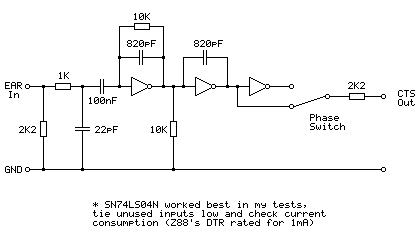
This is based on the tape interface circuit I devised for the Sega Master System and uses an SN74LS04N hex inverter chip as an amplifier to drive the Z88's CTS line. It's designed to be powered from the Z88's serial port which provides 5V at 1mA on the DTR pin. This current limit does seem awfully low and I have seen it reported as 10mA in some places but I'm not sure if that's a typo or not — the user manual states 1mA. In my testing this circuit consumes between 2mA-3mA which is much more than 1mA but it does still work, however I would strongly recommend doing your own testing before hooking anything up to your Z88's serial port. The other hex inverter chips I tried all consumed over 20mA in this use which is far too much for the Z88! There was a noticeable difference in current consumption depending on whether unused inputs were tied high or tied low, so please do your own testing.
The presence of a phase switch does allow this circuit to be used with recorders that reverse the phase when recording but don't provide a phase reversal switch of their own to fix this on playback.
All in all I'm very impressed that the Z-Tape software works as well as it does considering the simplicity of the hardware, and it's been a lot of fun digging into how it works.
Using a VDrive to access USB flash drives from a Cambridge Z88
Saturday, 13th May 2023
The VDrive is a handy module for electronic projects that need to access files on a USB flash drive. It's based around a USB host microcontroller and comes preinstalled with some firmware that provides control over the drive with simple commands sent via a serial connection (UART or SPI).
A few years ago I started putting together some code to connect the module to my Cambridge Z88 computer. All I needed was a way to power the drive and a MAX232 chip to translate the computer's RS-232 interface to the VDrive's logic levels, and after around 150 lines of BBC BASIC I had a program that could show directory listings, let me browse folders, and fetch files from the USB drive to the Z88's file system.
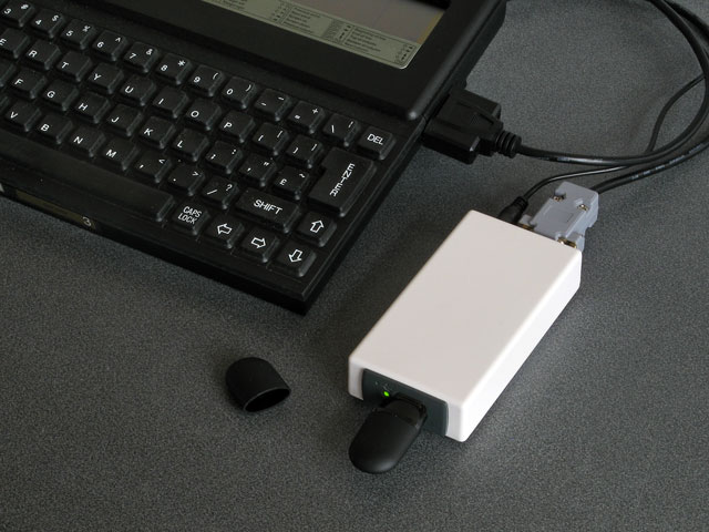
This worked well enough but was a bit clumsy. For example, to maintain good performance rather than alternate between reading a single byte from the drive and writing it to the local file system it's better to read and write larger chunks at a time. BBC BASIC doesn't provide a built-in way to do that, though you can read or write CR-terminated strings. When you read each part of the file this way you therefore need to decide whether the string you've just read is a certain length because you've reached a CR terminator (which isn't included in the read string), whether you've reached the end of the file, or whether the string buffer is full, and from that piece the file back together. I got this working quite well but it's still fundamentally an inelegant hack. Doing it properly would require some assembly code, and that would also be required for some other operations (such as properly transferring date and time modification information) that are otherwise not possible from pure BASIC.
Fortunately, BBC BASIC has a built-in assembler and that makes integration of assembly code in BASIC programs quite a bit easier than it would otherwise be. However, as I considered the amount of assembly code required would be quite high, I thought it might be more sensible to just rewrite the program as a native Z88 popdown application.

Status dialog shown when fetching a file from the drive
This is what I ended up doing, and it can be downloaded from its product page. It was quite a lot of fun to learn my way around the Z88's OS – not just for things like file handling, date and time manipulation, and integration with menu and help system but for some of the challenges involved in writing Z80 code for a system that shares memory between multiple running applications (and the file system) rather than my usual environment of having a big block of contiguous RAM to do whatever I fancied in.
The directory listing is the most obvious place where I had to rely on dynamic memory allocation. Each file or folder name being sent in a directory listing by the VDrive is allocated its own memory and I arranged the names together in a linked list that is sorted with an insertion sort.
Being my first Z88 application it's not especially well written but I've been using it for a while now and it seems to work well enough so I've released it, both on this very website and on GitHub.
Subscribe to an RSS feed that only contains items with the Z88 tag.