Building your own analogue sensors for the SmartBox
Friday, 29th November 2024
This is an extremely belated followup to a post from November last year, though one of the reasons for the delay was repeatedly being sent the wrong electronic components which ultimately led to the post from December. I'll try to explain as best I can...
Towards the end of last year I bought myself a SmartBox, a computer control system that's based around a 65C02 CPU and that runs programs written in an interpreted BASIC-like programming language, with software uploaded via a computer's serial connection (and once the programs are loaded onto the box, the serial connection can be severed and the program will continue to run). In the previous journal entry I focussed more on the software side, though to get practical use out of the box I had experimented with some of the hardware too and had built some analogue sensors that I was hoping to write up for the benefit of anyone else who'd acquired a SmartBox but none of the sensors to go with it.

Two home-made User Adaptors and two home-made temperature sensors.
The four analogue sensor ports on the side of the SmartBox use 5-pin DIN sockets (180° to differentiate them from the 240° 5-pin DIN socket used for the serial port). Each sensor port can measure an analogue value with an 8-bit resolution (between 0 and 255) with the maximum voltage refererence being set to 2.55V – that is, each unit in the 0–255 range reported by the sensor corresponds to 1/100V (10mV), so if you connected a 1.5V source to the sensor port you'd see a value of 150 returned.
Sensors were made that measured specific physical properties (such as light level, humidity, temperature, or sound level) as well as generic "User Adaptor" boxes that allowed users to connect their own sensors:

The SmartBox "User Adaptor" pictured in a brochure.
One other nice trick that the analogue sensors had was that they could report which type of sensor they were directly to the SmartBox, so when you plugged in a temperature probe (for example) it would know that it was measuring temperature on that sensor port. The way this was implemented is via a "sense signal" output pin from the SmartBox to the sensor. In normal operation it was low, and the voltage read on the analogue sense input pin was used as the sensor's current value. Once a second or so the SmartBox would drive this pin high, and the voltage read on the analogue sense input pin was used to determine the type of sensor.
There are 32 possible sensor IDs. The ADC reading mentioned in the table below is the minimum value that will cause the Smart Move software to identify a particular sensor, for example a humidity sensor can be identified with an ADC reading between 157 and 164:
| ADC | Smart Move 1.16 | Smart Move 1.18 |
|---|---|---|
| 0 | No sensor | No sensor |
| 5 | mT | |
| 13 | mm | Temp |
| 21 | No sensor | No sensor |
| 29 | No sensor | No sensor |
| 37 | Temp | Volts |
| 45 | Temp | Temp |
| 53 | mA | Volts |
| 61 | Sound | Temp |
| 69 | Sound | Sound |
| 77 | Sound | PH |
| 85 | Pulse | |
| 93 | Position | Position |
| 101 | ||
| 109 | ||
| 117 | ||
| 125 | Light | Light |
| 133 | ||
| 141 | ||
| 149 | ||
| 157 | Humidity | Humidity |
| 165 | Sound | |
| 173 | Light | |
| 181 | Pressure | Sound |
| 189 | ||
| 197 | PH | Atmos |
| 205 | Light | |
| 213 | User | |
| 221 | Adaptor | Adaptor |
| 229 | Lux | Temp |
| 237 | Volts | LGate |
| 245 | Wind | |
| 253 | Temp | Temp |
Note that Smart Move 1.16 and Smart Move 1.18 have some different names for some sensors. If a space is left blank in the table then the sensor is treated as present but is labelled "SENSORA" to "SENSORD" instead of being renamed according to the sensor type.
An analogue multiplexer (such as a 4053 IC) can be used as the basis for an analogue sensor for the SmartBox, sending either the voltage to measure or a reference voltage set with a preset potentiometer to identify the sensor type. The "sense signal" output from the SmartBox chooses which of the two voltages to return:

When the adaptor is connected to the SmartBox the potentiometer RV1 can be adjusted to choose the sensor type. As this is only checked once per second it can be a little fiddly to dial in the specific value you want — temporarily bridging A0 and A1 on the 4053 (so that RV1 is used as both sensor type and input value) and watching the reported sensor value can make life easier (making sure any sensor is disconnected from the input socket, of course).

The internal components of the home-made User Adaptor.
Whilst this is a useful circuit for building custom sensors, or making a replica of the generic User Adaptor (my DIY effort pictured above) there is a simpler option that can be used for temperature sensors. The original temperature sensor doesn't seem to have very much circuitry of its own, being just a simple probe with a DIN socket on the end of a wire:

The SmartBox "Temperature Sensor" pictured in a brochure.
The temperature sensor provides a reading in Celsius directly in the software, e.g. a temperature of 25°C is reported with a value of 25. This corresponds to a 10mV/°C sensor, and an example of such a sensor is the LM35. One limitation of the LM35 is that without a negative supply voltage pulling down its output it reports a minimum temperature of 2°C, yet the brochure snippet shown above reports a range of 0°C to 100°C. However, reading the manual for the SmartBox it mentions that the Smart Sense temperature sensor measures temperatures between 2°C and 100°C which seems to further indicate that it is indeed something like the LM35.
We could therefore just connect an LM35 to the User Adaptor circuit shown above and that would work, however there is a simpler circuit. If you consult the table of sensor types at the start of this post you'll notice that the temperature sensor appears at the bottom of the table with the highest sensor value. This means that to be identified as a temperature sensor, the sensor must output at least 2.53V when the "sense" pin goes high. A crude way to implement this is to connect a diode from the sense output pin back to the analogue input pin:

When the sense pin is low the voltage at "input" will be higher than the voltage at "sense" so the diode will not conduct and not influence the output of the temperature sensor. When the sense pin is high, however, the voltage at "sense" will be higher than the voltage at "input" and so the diode will conduct and raise the voltage at "input" to above 2.53V, indicating that the connected sensor is a temperature sensor.

The internal components of the home-made temperature sensor.
According to the documentation for the SmartBox the inputs are protected against overvoltage so I believe this is a safe circuit to use, however as with the User Adaptor all circuits here are based on some rough guesses as to how the devices would have originally worked as I don't have any real sensors to test with myself. In any case, these sensors work for me as I've not been able to source any of the original parts, so maybe if you like me have an old SmartBox knocking around these may help you get some more use out of it.
SmartBox experimentation with DOS, RISC OS and C#/WinForms
Monday, 6th November 2023
My latest eBay purchase was influenced by a desire for some practical test/prototype equipment, a bit of nostalgia and a desire to learn something new.
A lot of my projects involve some sort of microcontroller running some software that will take inputs, perform decisions on them, and produce outputs. Getting to that stage tends to involve quite a lot of "boilerplate" hardware and software setup, and I'd quite like something that I can just plug in and get cracking with and write some quick test code instead of having to assemble a circuit on a breadboard or faff around with a clumsy IDE.
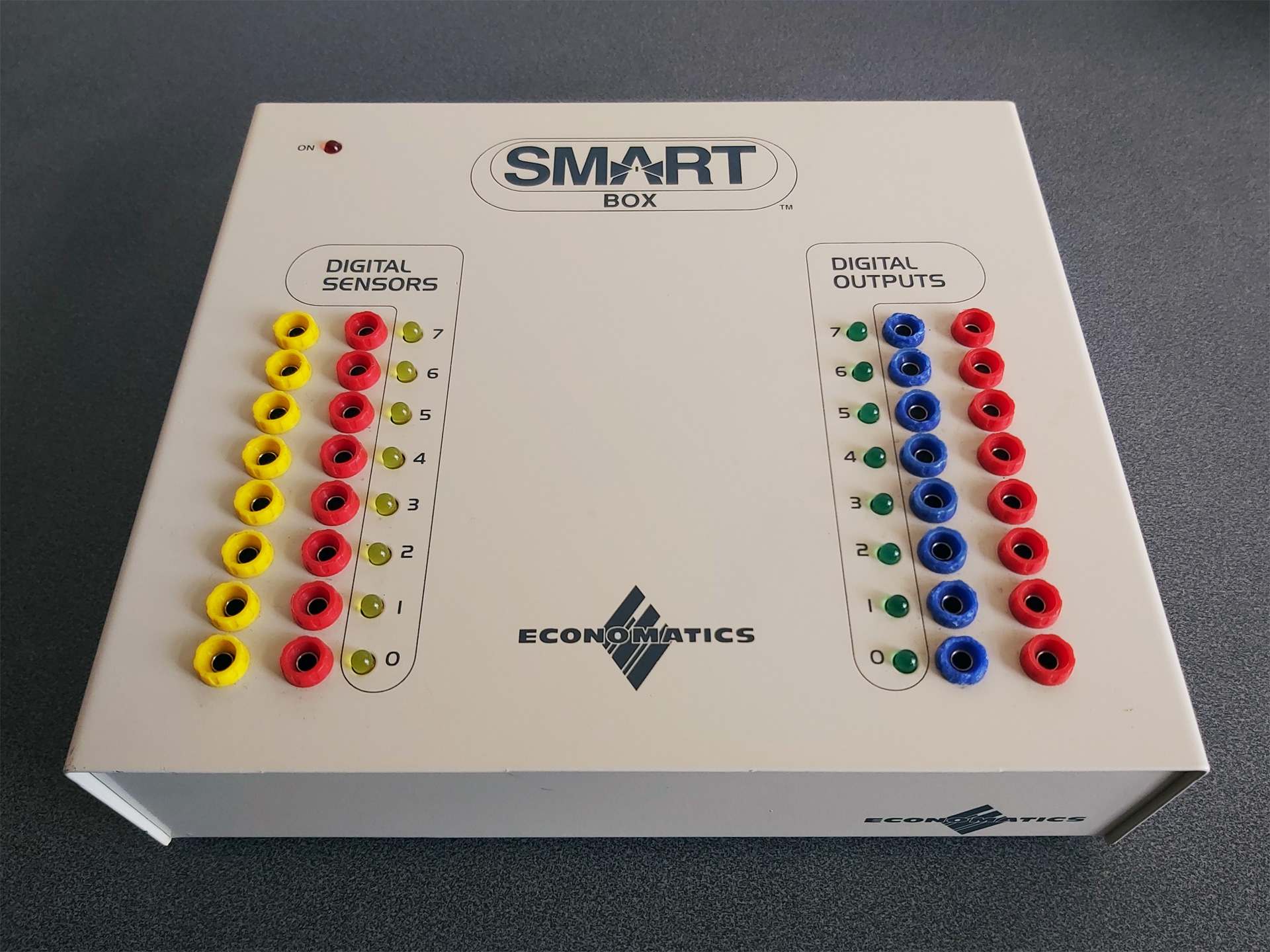
When I was at school in the 1990s one of the devices that got me into microcontrollers in the first place was a computer control system based around the Economatics SmartBox. This plugs into a computer via a serial connection, has eight simple digital inputs, eight simple digital outputs, four analogue inputs and four motor drivers. Programs could be written in a BASIC-like language or in flowchart form, and once you'd run and tested them on the SmartBox you could program them to a PIC microcontroller to run without the host computer.
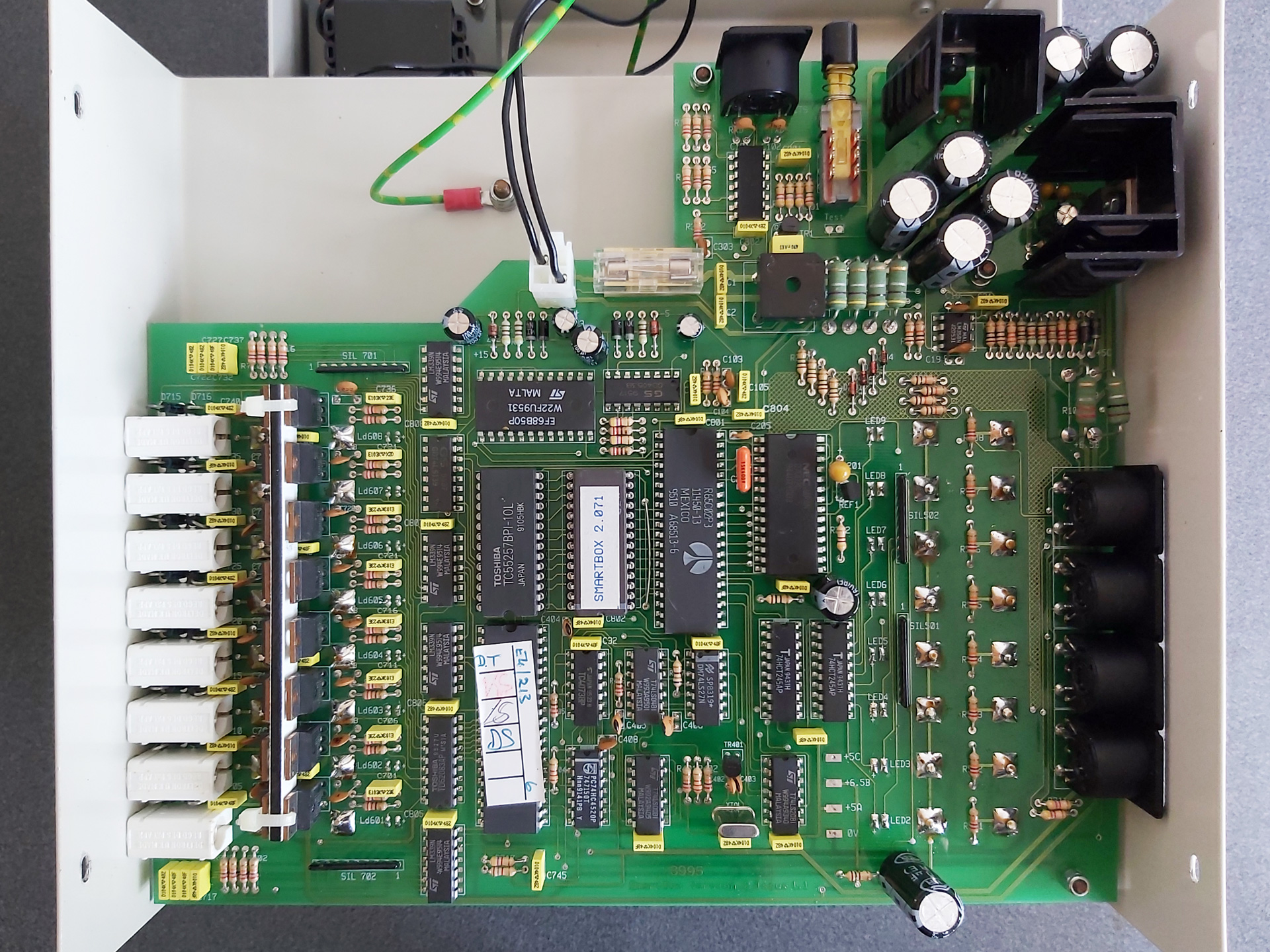
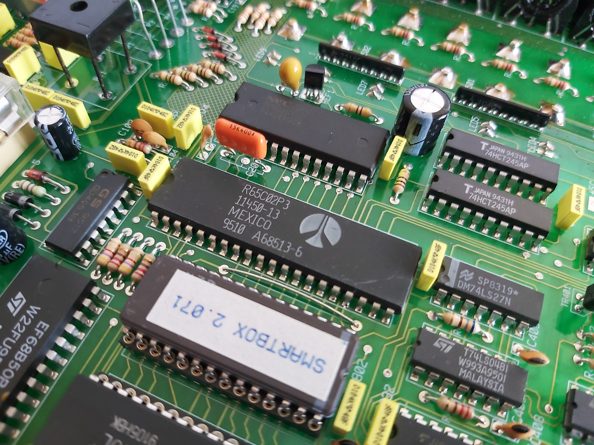
All along I'd assumed that the SmartBox was a simple interface box that relied on the host computer to do all of the processing, but doing some digging I found a thread on StarDot that delved into the heart of the machine and saw that there's a 65C02 CPU inside along with 32KB of RAM and the OS runs from a socketed 8KB ROM. As a long-term Z80 fan I thought it was time I should see how the other side lived – in spite of my fondness for the BBC Micro I don't own one and have not programmed any 6502 assembly, so a SmartBox seemed like it would also provide an affordable 6502 computer for experimentation.
Of course, one challenge was going to be finding the supporting software for the venerable SmartBox. Fortunately in the StarDot thread people had shared archives of the DOS, BBC Master and RISC OS software. One of the many handy features of DOSBox-X is its ability to connect an emulated serial port to a physical one in the host system, and so after building a serial cable for my SmartBox (using a pinout found, once again, via the StarDot thread) I was able to hook it up to my PC and get it working with SmartMove, the BASIC-like programming environment for the SmartBox.
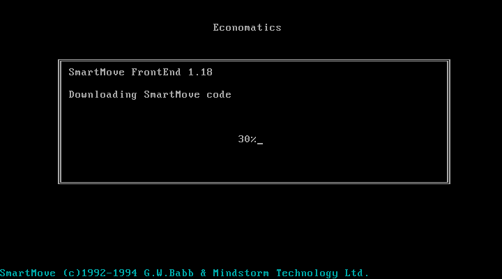
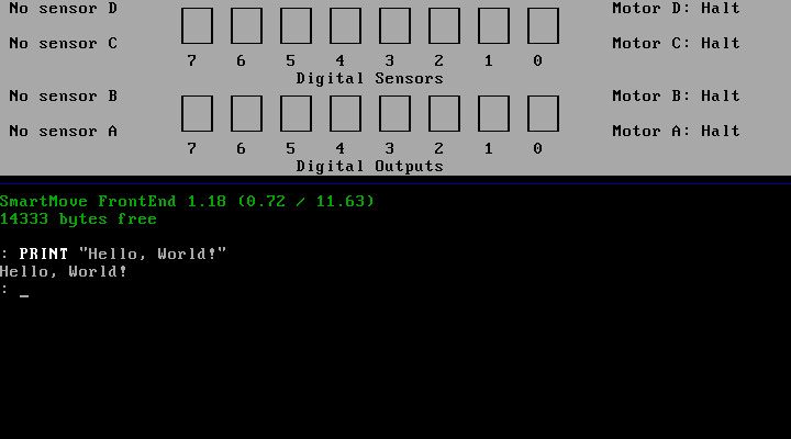
When the software is first run it needs to download SmartMove code into the SmartBox. This is because the programming environment and interpreter is actually running on the SmartBox itself, and the SmartMove software on the host PC is simply loading that interpreter onto the box (found in an accompanying file of 65C02 machine code named AL.COD) and then providing a user interface to that environment as a sort of terminal. This means you can close the SmartMove software (and unplug the serial cable) and your program will continue running on the SmartBox.
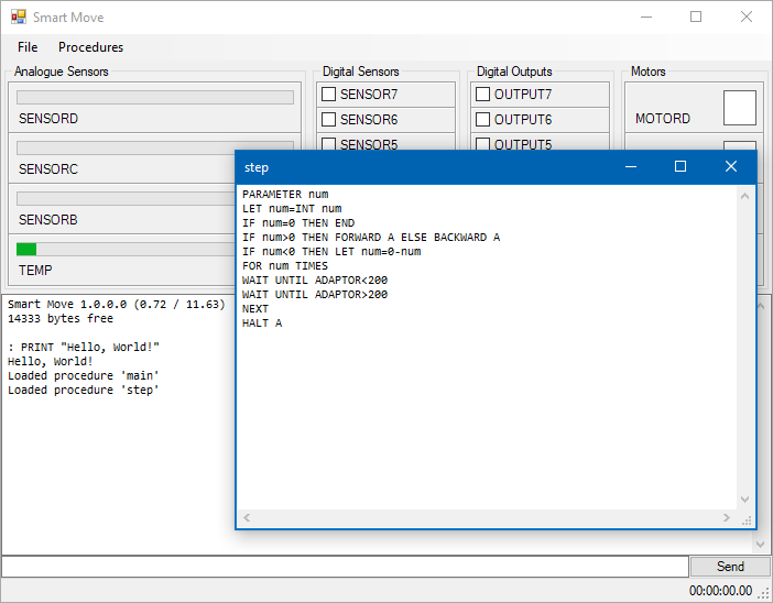
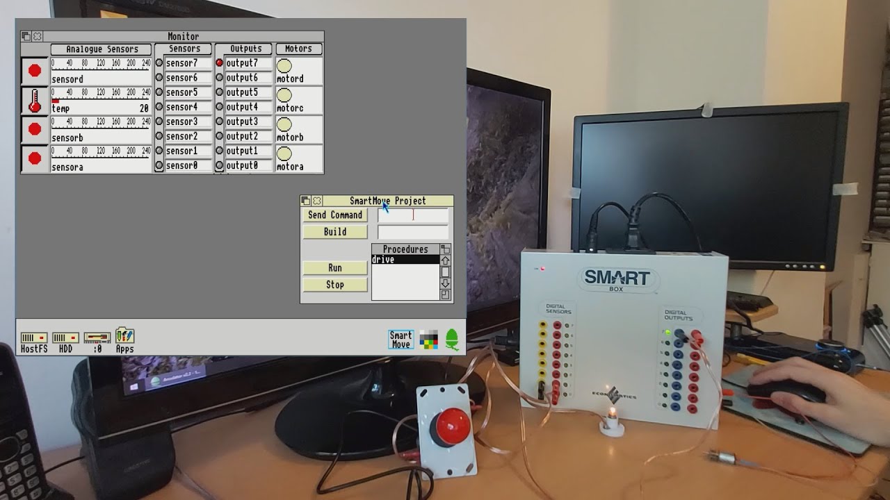
This ability to load and execute code directly on the SmartBox is one of the things that intrigued me as a way to get into 65C02 programming, but for the time being I was interested in digging deeper into the how the existing SmartMove software was interfacing with the box with the intention of writing a simple Z80 host interface that I could then adapt to the Cambridge Z88, my CP/M computer and maybe even the TI-83 Plus calculator series. Fortunately the documentation for the serial protocol used by SmartMove application has been documented so I was able to prototype a crude version of the software in C# using WinForms. It needs some serious tidying up before I can release it but as a basic test it does the job:
The ability to build new versions of the interface software for different platforms without needing to worry about porting over the BASIC interpreter seems sensible considering there were versions of SmartMove available for DOS, BBC Master, RISC OS and Apple Macintosh. All could use the same AL.COD but would just need to provide the relevant UI, input and output routines specific to their host platforms.
I had been using the DOS version of SmartMove as the initial inspiration of the user interface for my C#/WinForms implementation, however the screenshots of the RISC OS version in the user manual looked rather more visually appealing and an archived copy of this software was available. Unfortunately, I don't own an Acorn Archimedes, I was unable to get the software running properly on modern RISC OS on a Raspberry Pi (even with various compatibility shims in place) and I couldn't find an emulator that handled the serial port in a similar fashion to DOSBox-X. However, the excellent Arculator has source code available and armed with a copy of the 6651 UART datasheet I thought I'd have a go at hacking in the feature myself.
"Hack" is definitely the operative word and though my code is abominable it does work well enough to get the available RISC OS software working on my PC. It's downloadable from here and requires the addition of the host PC's serial port name to arc.cfg (e.g. serial_port = COM1).
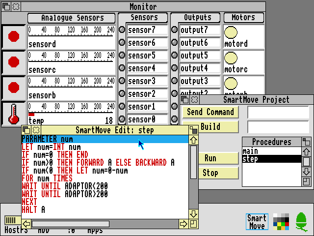
The above screenshot shows the RISC OS version of SmartMove which provided some additional inspiration for how a GUI version of the software should work. As I'd previously loaded some procedures onto the SmartBox via my C# version I could then bring the same procedures up for editing in the RISC OS version of the software. Handy!
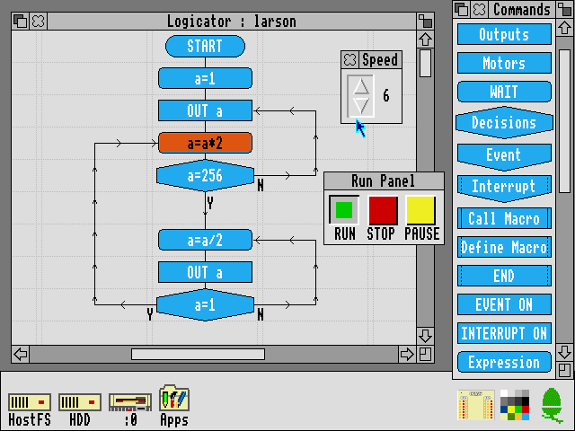
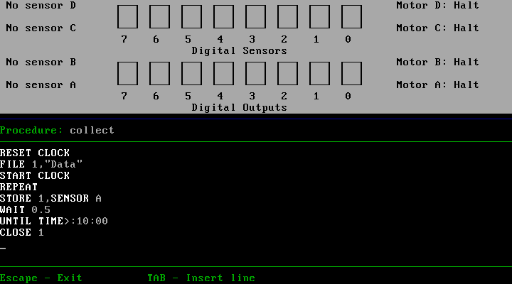
The Logicator software can be used to build programs using flowcharts instead of a BASIC-like programming language. As far as I'm aware Logicator directly accesses the inputs and outputs from a number of different host interface boxes and doesn't rely on 65C02 code loaded onto the box like SmartMove, but this does mean that when you close Logicator your program stops aas it's relying on the host PC to run the show. However, included with the archive of RISC OS software is an application called SmartFlow which first loads a flow chart "interpreter" into the SmartBox:
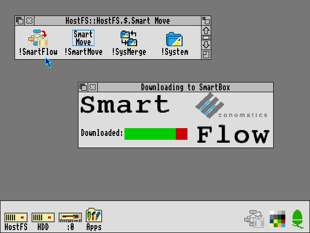
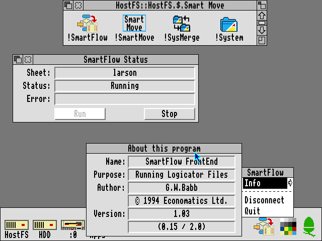
Once loaded you can then load a Logicator-format flowchart onto the SmartBox where it can be run without being connected to a host PC:
All in all it's been quite interesting to dig into the SmartBox and get a feel for how it works and what can be done with it. To this end I recorded a video demonstration of the SmartBox and its usage within RISC OS, though so far I feel I'm only really scratching the surface!
Subscribe to an RSS feed that only contains items with the SmartBox tag.