A useful Z80 computer in a project box
Saturday, 14th August 2010
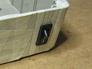
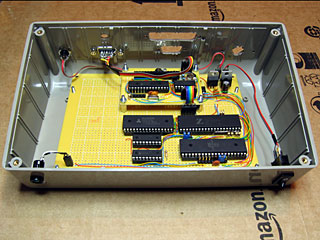
Work continues on the Z80 computer. The two final modifications to the box itself are the holes for the status LEDs and the power switch.
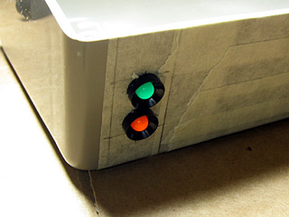
The green LED indicates power and the orange one disk activity. Unfortunately, the project box is fairly scratched on the outside (one scratch on the front is my own fault, but the sides and back were fairly scuffed and scratched when I bought it). If anyone has any tips for polishing scratches out of ABS I'd be glad to hear them; the usual household polishing abrasives (such as toothpaste) remove most of the light scuffs and result in a lovely mirror finish, but don't do anything to the deeper scratches. I'll probably invest in the finest grade wet-and-dry sandpaper I can find and have a go with that followed with a Brasso polish, and if that doesn't help (or makes it worse) just sand the whole thing down and paint it.
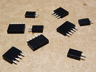
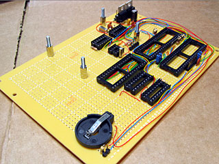
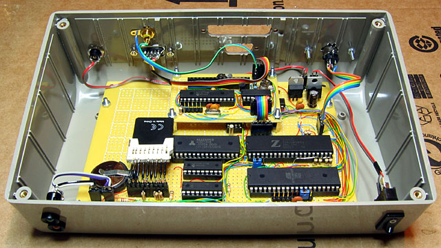
The circuit board inside the case needs to be attached to the case-mounted components somehow. In simpler projects I've resorted to soldering these connectors directly to the board, but this can make maintenance a problem (to remove the circuit board one would have to cut and resolder the wires). For this project I've left pin header strips on the board. The external connectors have leads soldered to them terminated with pin headers cut to size using some wire cutters and a rotary tool to polish them off; these headers are pictured above.
The main circuit board can then be easily installed or removed from the case as required. The small circuit board for the video display controller is connected to the main circuit board in the same way.
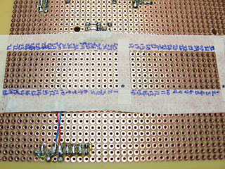
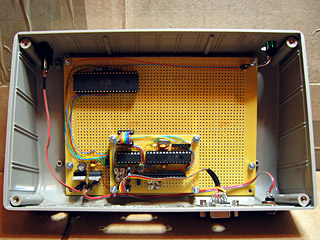
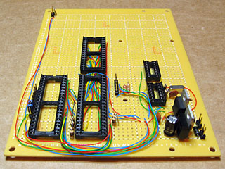
A Z80 computer can't live up to its name without some sort of a Z80 inside it, so I thought that that was the most obvious part to add next. Computers also generally need access to memory so I decided to add the 128KB SRAM chip at the same time. The Z80 communicates with the memory over an eight-bit data bus, a sixteen-bit address bus (to indicate which address in memory it is reading from or writing to) and a number of control lines (to indicate whether the current operation is a memory read or a memory write, for example). This provides a fairly tedious amount of soldering work; each pin on the memory needs to be connected to the corresponding pin on the Z80. To aid in the construction I stuck masking tape to the bottom of the perfboard around the outline of where the two chips would go and wrote the pin numbers onto the tape, shown in the photograph above.
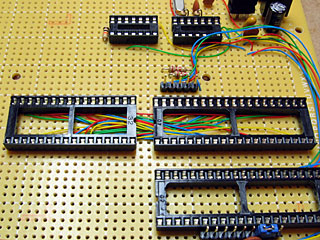
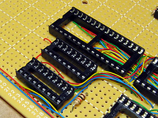
I put the two chips close together so I could put all of the bus wires on the inside of the IC holders rather than going around the outside. This saves a bit of space and avoids having to route the wires around the chip holders which gets a little untidy. The above photograph shows all of the wires in place before the chip holders were soldered in. Adding those in should be a quick and easy job, at least...
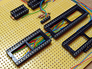
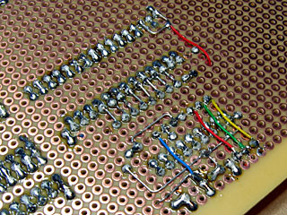
Well, you'd have thought so, but somehow I managed to solder in the 32-pin SRAM socket the wrong way around. Each socket has a notch to help you align the chip using its corresponding notch. As you can see in the above photo the notch points right when it should point left like all of the other sockets. It wouldn't affect the operation of the circuit (as long as the SRAM chip was inserted with the notch to the left) but it looks untidy and I may as well do the job properly.
On the positive side I suppose I got to practice my desoldering skills.
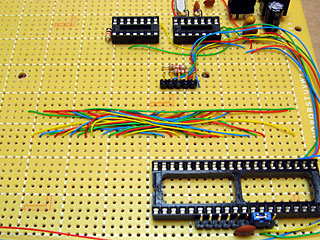
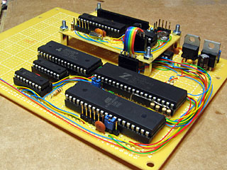
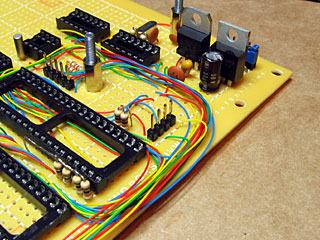
The computer design uses an AVR microcontroller to manage the I/O devices (such as the keyboard, video display controller and SD card) and to load the OS into the Z80's memory on reset. To achieve this the Z80 and the AVR need to be connected together. The above photograph shows some new wires between the AVR (bottom left) and Z80 (bottom middle) to connect the Z80's data bus to the AVR's PORTA and a number of other wires to connect the Z80's control lines to several other I/O pins on the AVR. A number of pull-up resistors have been added to control lines on the Z80 so that when nothing is driving the control bus they rise high (the de-asserted state). If left disconnected ("floating") the other components connected to the control bus may think these lines had gone low (asserted) and treat that as a read or write operation, corrupting data.
The AVR also needs to be connected to the Z80's address bus. This would take another sixteen pins if driven directly by the AVR; sixteen pins that aren't available to me! I am therefore using two MCP23S08 eight-bit I/O expanders, pictured above, to drive the address bus from the AVR. These are controlled over the SPI bus, which only takes up three pins on the AVR (these pins are shared with other SPI peripherals, such as the SD card) plus a single chip select pin that is unique to the I/O expanders. Four pins is better than sixteen, at any rate.
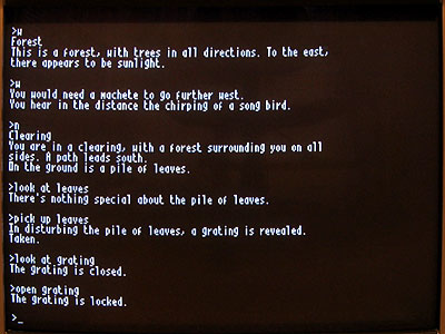
I keep mentioning chips even though the sockets are quite clearly empty in the above photographs. As I was approaching a useful computer circuit at this point I plugged all of the chips into their sockets to test the connections. As there was no SD card, real-time clock or keyboard I had to modify the boot loader on the AVR quite considerably; I started with a test program that wrote random data to blocks of memory then read them back to verify that they had written correctly. Once I had verified that the AVR was able to access memory correctly I reprogrammed it to copy a small Z80 program to memory and then let the Z80 take over. This Z80 program repeatedly output the string 'Z80' to the console output port. With everything plugged in I switched on the computer and saw the screen fill with Z80Z80Z80… so I was pretty certain that I'd wired everything up correctly!
At this point I could start reintroducing the various peripherals to the computer. A DS1307 is used as a real-time clock. This clock needs to keep running when the computer is switched off, so I've added a 3V battery connector to the computer to keep it ticking.
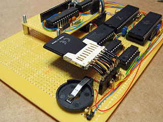
As the computer uses a 512MB SD card for storage, I have added a pin socket strip to the board to plug in the SD card slot I scavenged from a card reader. The card is connected to the SPI bus along with the I/O expanders used to drive the Z80 address bus. SD cards run at 3.3V rather than the 5V that nearly everything else on the board uses so I've used a series of voltage dividers to drop the voltage on each input pin from 5V to around 3V (the resistor values I have don't allow me to get to 3.3V; 3V is the closest I can manage without going over 3.3V). The video display controller board also runs on 3.3V so I do at least have a suitable voltage supply for the card!
The final part of the computer that was on the breadboard prototype but not yet in the final build was the keyboard connector. This is simply a four pin header on the board that is connected to the PS/2 port screwed to the case. However, when I tried to use the computer, the keyboard didn't appear to work. Pressing Num Lock, Caps Lock or Scroll Lock would toggle the associated LED and hitting Ctrl+Alt+Del would reboot the computer but no other key worked. This implied that the AVR was handling the keyboard correctly but the Z80 wasn't receiving any notification of key presses. A bit of digging identified the problem; I'd forgotten to connect the Z80's interrupt pin to the AVR! When a key is pressed the AVR triggers an interrupt to let the Z80 know that a key is available. By soldering a wire between the two chips it started working as intended.
The computer is now up to the same standard as it was when assembled on the breadboard, but is much more practical to work on. I hope to add a serial and parallel port to the computer soon, and would like to mount an LCD into the lid of the project box, but for the time being I am happy that I have managed to get this far.
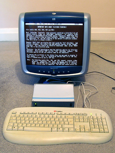
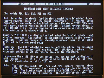
One of the advantages of running CP/M on the computer rather than my own operating system is the availability of existing software. The above photograph shows the computer running VEDIT, which is an excellent visual text editor.
With the hardware in a decent configuration I can start writing my own software. I think the first CP/M program I'll write is a graphical analogue clock, as this is the sort of program that can be left running for long periods as a way to check the stability of the computer.