A clock and a serial port for the Z80 computer
Tuesday, 17th August 2010
At the end of the previous entry I mentioned that I was going to start developing my own programs for the Z80 computer. The first is a graphical clock, taking advantage of my implementation of the BBC Micro's VDU commands and the ability to use those commands to draw graphics onto the screen as well as text:
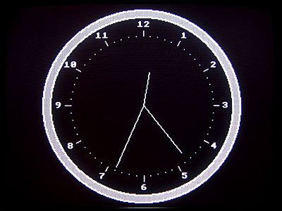
I have uploaded the code and binary to my site for anyone who is interested, though it will only work on a machine running CP/M 3 and that is equipped with a display that implements a handful of BBC Micro VDU commands.
The computer features a display for output and a keyboard for input which is sufficient if you're interacting with a human but it's often nice for computers to be able to speak to eachother, so I've added an RS-232 serial port.
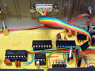
RS-232 is a bit of an unfriendly beast. Whereas the computer's logic uses 0V to indicate a logic low (0, "false") and 5V to indicate a logic high (1, "true") RS-232 uses around +12V for a logic low and -12V for a logic high. This requires that the outgoing signals are inverted and boosted and the incoming signals are inverted and reduced to protect the inputs of the receiver circuit. Fortunately you can easily get hold of chips that perform this task for you when aided by a number of capacitors; in my case I'm using an ST232, which is shown in the bottom left of the above photo. A DE-9M connector is provided on the outside of the case, much like the one you'd find on your desktop if you were trapped in the 1990s.
One issue I have yet to solve is handshaking. The serial port sends or receives data on two wires (TXD and RXD respectively). The receiver has to handle each incoming byte from the transmitter. As the receiver may be busy performing other tasks at the time it may end up receiving data faster than it can process it and it will start losing bytes. There are a number of different ways to avoid this problem. The simplest electronically is to use XON/XOFF handshaking; in this configuration, the receiver can send the XOFF byte to the transmitter when it's busy and the transmitter will stop sending data temporarily. The receiver can then send XON back to the transmitter when it's ready to receive more data. This technique has one major drawback it prevents you from sending binary data containing the XOFF or XON bytes.
An alternative solution is to add two wires to the serial connection Request To Send (RTS) and Clear To Send (CTS). These can be used to signal when each device is available to accept data. This allows you to send XOFF and XON directly over the serial port (extremely useful for binary data) yet requires the addition of two more wires to the port.
Unfortunately whilst implementing both techniques is possible, CP/M only internally refers to XON/XOFF handshaking; there is no way to select RTS/CTS handshaking. I think what I will end up doing is have CP/M's XON/XOFF refer to handshaking in general and then add a hardware-specific utility that lets me choose which particular type of handshaking I wish to use. This utility could also help me select other serial port configuration settings that CP/M doesn't expose (such as parity, number of stop bits or number of data bits).
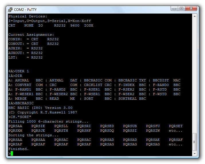
With the hardware installed, the AVR I/O controller updated to use it and the BIOS reprogrammed to expose it to CP/M it is possible to interact with other computers over the serial port. CP/M features five logical I/O devices: CONIN and CONOUT for general console input and output, AUXIN and AUXOUT for general "auxiliary" output and LST for printer output. The BIOS exposes two physical devices; CRT for the keyboard and video display controller and RS232 for the serial port. By using the DEVICE utility you can connect these logical and physical devices together. In the above screenshot I have connected the serial port to both CONIN and CONOUT. This allows me to connect my desktop PC to the Z80 computer using a null modem cable and use terminal emulation software (such as PuTTY) to talk to it.
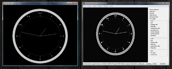
The above screenshot shows VirtualDub capturing the output of the video display controller next to an instance of BBC BASIC for Windows which is running the following program:
aux%=OPENIN("COM2: baud=9600 parity=N data=8 stop=1")
REPEAT
  REPEAT:UNTIL EXT#aux%
  VDU BGET#aux%
UNTIL.
This passes any data received over the serial port to the simulated VDU in BBC BASIC for Windows. As both video devices accept the same commands the result is that both show approximately the same thing.
I have been slightly improving the video display controller as I've gone along. One feature I had to add for the clock was the ability to draw text characters at the graphics cursor position, as opposed to the fixed text grid (this is used to draw the numbers around the dial). At the same time I added the ability to redefine the appearance of characters. One obvious use of this feature is to change the font, but when combined with the ability to render text anywhere on the screen some simple sprite-based games could be written for the computer. Each letter is just a 8×8 pixel sprite, after all.
Another feature I added was a simple implementation of MODE 2 where characters are stretched to sixteen pixels wide. You can't get much text on the screen in this mode but it may be useful for games.