Better drawing, editing, memory and emulation for BBC BASIC on the Sega Master System
Tuesday, 3rd August 2021
I have continued to work on the Sega Master System version of BBC BASIC, and it's feeling much more like a practical version of BASIC than something that was just holding together to run one specific program!
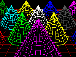
One of the key improvements is to standardise the handling of the different graphics modes. Previously I was using a coordinate system where (0,0) is in the top left corner and all drawing operations were carried out using physical device coordinates (so the screen was treated as being 256 pixels wide and 192 pixels tall). I have now moved the origin (0,0) into the bottom left corner with the Y axis pointing up and scale down all coordinates by 5, effectively making the screen 1280 logical units wide and 960 units tall. This isn't 100% compliant, as the BBC Micro and other versions of BASIC treat the screen as being 1024 units tall, but dividing by 5⅓ is considerably trickier and it would result in the graphics being squished further vertically, so I think using a logical resolution of 1280×960 is an acceptable compromise. I've added some VDU statements to allow you to move the graphics origin as well as define custom graphics and text viewports, so you can control where on the screen graphics and text appear and how they are clipped/scroll.

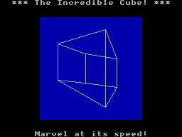
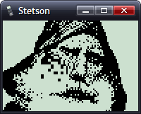
The output of the "Mandelbaum" program following these changes
I have also changed the default palette to more closely match the one used by the BBC Micro and other versions of BBC BASIC. This isn't too difficult when using the Master System's "Mode 4" as that has a user-definable palette, but the legacy TMS9918A modes have a fixed palette so I've tried to match the default palette as sensibly as I can to the TMS9918A palette. It's possible to change the logical to physical palette mappings under Master System "Mode 4" via a VDU command which writes directly to the CRAM (you can either remap one of the 16 logical entries to one of the stock 16 colours, or supply an RGB value directy to select additional colours) which allows for neat tricks like palette cycling, but the TMS9918A modes currently only let you change the current text/drawing colour, not amend the palette as that's fixed in hardware.
I've also added filled/outlined circle and axis-aligned ellipse PLOT commands using some code written by Darren "qarnos" Cubitt which I originally used in the TI-83 Plus version of BBC BASIC. This code is very capable and fully accepted 16-bit coordinates for its inputs, however it was also originally designed to output to a 96×64 pixel screen so the final plotting was done with 8-bit coordinates ranging from -128..127. Fortunately the Master System's screen also fits in 8-bit coordinates at 256 pixels wide but that's not quite enough information as you also need to be able to tell if a particular point is off-screen (less than zero or greater than 255); simply clipping it against those boundaries will result in a vertical smear on the left or right edge of the screen when drawing outlines. Fortunately I was able to figure out how to modify his code to add some extra clipping status flags to ensure that ellipses were clipped and displayed correctly on any part of the screen.

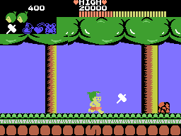
Filled circles and filled/outlined ellipses make these drawings possible
The only graphics operation exposed by the mode-specific drivers before was a simple "set pixel" routine. This is fine for lines but quite slow for filling shapes so graphics mode drivers can now supply a "fill horizontal span" routine for faster shape-filling. If the routine is left unimplemented a stub routine is provided that fills the span using the "set pixel" routine.
I also added a rectangle-filling PLOT command, which is perhaps not the most exciting-sounding graphics operation but it is used to clear the screen so it is at least useful. More interesting is a triangle-filling routine, something I've never enjoyed writing!
Usually I get very bogged down in the idea that the pixels affected when you fill a triangle should exactly fit within the pixels that are outlined by drawing lines between each of the triangle's points, no more and no less. This can be a bit difficult when the triangle is filled by tracing its edges from top to bottom and drawing horizontal spans between them. If the edge is "steep" (its overall height is greater than or equal to its width) then this isn't too bad, as there's only one X coordinate for each Y coordinate where a pixel would have been plotted. However, when the edge is "shallow" (its overall width is greater than its width) there are going to be certain Y coordinates where the line drawn would have had multiple pixels plotted. In that case, where is the boundary of the horizontal span?
The cop-out answer I've used in the past has been to set up three buffers the total height of the screen and to "draw" the three lines first using the same line-drawing algorithm as the line PLOTting command, keeping track of the minimum and maximum X coordinate for each Y coordinate. When it's time to fill the triangle the minimum and maximum X coordinate for each edge can be determined based on the current Y coordinate and a span drawn between them for perfect triangles. On the TI-83 Plus this takes up four bytes per line (minimum and maximum 16-bit values) for a 64 pixel tall screen, with three buffers for the three lines that comes to 4×64×3=768 bytes, pretty bad. On the Sega Master System that would be 4×192×3=2304 bytes, totally unacceptable on a machine with only 8KB total work RAM!
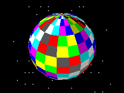
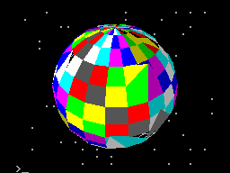
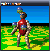
Each face of this 3D sphere is filled by two triangles.
I've instead simply done my best to interpolate from one X coordinate to the other when working my way down the triangle and filling scanlines, doing a bit of extra pre-incrementing and fudging of initial error values depending on whether it's the top half or bottom half of the triangle. My test was to draw the outline of a triangle in bright white and then to fill a dark blue triangle over the top, if any bright white pixels were visible around the outside this indicated a gap. I mostly got it filled, but I then tried my test program on a BBC Micro emulator and found the BBC Micro exhibited similar gaps so I don't think I'm doing too badly! The above screenshot of the 3D sphere was rendered using this triangle-filling code.
I've also been working on improving the line editor. This is called by BASIC when it's asking for a line of text input from you. Previously I'd only implemented adding characters to the end of the line and pressing backspace to remove characters from the end of the line; if you'd typed in a long piece of code and made a mistake at the start you'd need to backspace all the way to the mistake, correct it, then re-type the rest of the line. Now you can use the cursor keys (or home/end) to move around within the line, insert or overwrite new characters (toggled by pressing the insert key on the keyboard) at the cursor position or backspace/delete characters mid-line as required. It sounds like a small thing but it was quite a lot of code to get right and makes a big difference for usability!
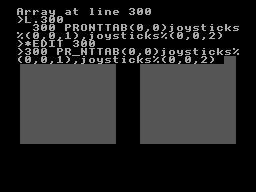
Another feature I've added to aid modifying lines of code is the *EDIT command. This takes a line number as an argument and then brings up the program line you've requested in the line editor, ready for editing. The way this works is a bit sneaky, as it's not natively implemented by BBC BASIC! The trick that makes it work is the ability to override two routines, OSLINE (which BASIC calls when it wants to display the line editor) and OSWRCH (which BASIC calls when it wants to output a character).
When a valid *EDIT <line> command is entered, OSLINE is overridden with the first custom routine. This routine doesn't ask for a line of input, but instead copies L.<line> to the input buffer, overrides OSWRCH with a routine that captures data to RAM, overrides OSLINE with a second custom routine, then returns. BASIC therefore thinks you've typed in a LIST statement so it dutifully starts outputting the line via OSWRCH, but this has been overridden to write the characters to RAM rather than the screen. When it's done this BASIC then calls OSLINE again for the next line of input, which brings up the second custom OSLINE handler. This pulls the data from RAM previously captured by the OSWRCH handler, copies it to the OSLINE buffer, and dispays it on-screen as if you'd just typed it in. It then restores the original OSLINE and OSWRCH handlers before jumping back into the stock OSLINE routine, so you can continue editing the line that you'd requested via *EDIT.
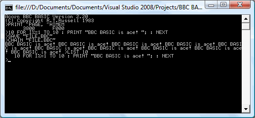
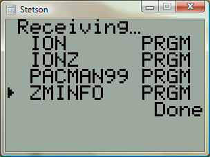
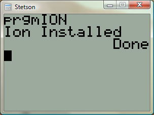
All of this hopefully makes entering programs via the keyboard less cumbersome. Of course, not having to type in programs in full every time you wanted to run them would be even better, and an attempt to give BASIC more memory provides another way to load programs in a somewhat roundabout manner.
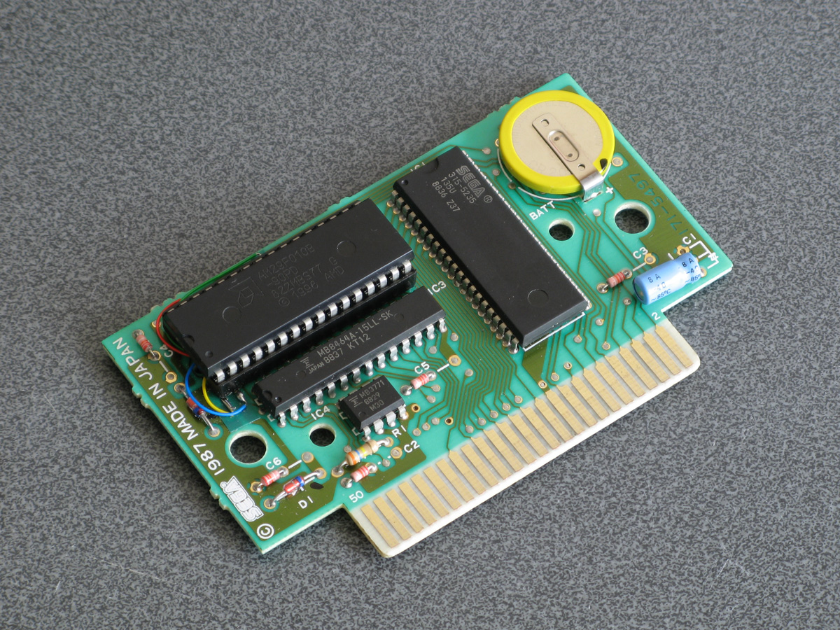
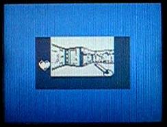
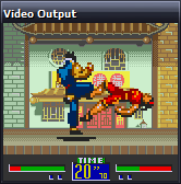
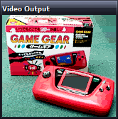
The photograph above shows the modified Monopoly cartridge that I'm now using to test BBC BASIC on real hardware instead of the modified After Burner cartridge I was using before. The advantage of Monopoly is that it has an additional 8KB RAM on board, which is used to save games in progress. Sega's cartridge mapper allows for on-cartridge RAM to be mapped into the address range $8000..$BFFF, immediately below the main work RAM which is at $C000..$DFFF. If present, then, BASIC's memory range (which runs from PAGE to HIMEM) can be extended by enabling the save RAM and moving PAGE down.
$8000..$BFFF is a 16KB range, though, and I mentioned that Monopoly has an 8KB RAM. This is true, and what it means is that the 8KB cartridge RAM is accessible from $8000..$9FFF but is then repeated ("mirrored") from $A000..$BFFF. The cartridge RAM detection therefore has to check two things: firstly that there is RAM in the first place (which can be verified by modifying memory at $8000 and seeing if those values stick) and how big it is (which can be checked by writing to $8000 and seeing if that has also modified the data at $8000+<RAM size>). Once presence of any RAM has been determined during startup, RAM mirroring is checked in 1KB, 2KB, 4KB and 8KB offsets. If any RAM mirroring is detected, then it's assumed the RAM is the size that was being checked at the time, however if not it's assumed that the RAM is the full 16KB. At this point, PAGE (which is $C000 in a stock machine with no cartridge RAM) is moved backwards by the size of the detected cartridge RAM, e.g. to $A000 for an 8KB RAM and $8000 for a 16KB RAM. This results in 16KB or 24KB total available to BBC BASIC, a considerable upgrade from the plain 8KB work RAM!
An added bonus of this is that when you type in programs they grow upwards in memory from PAGE. As PAGE now starts within your cartridge memory, and that cartridge memory retains its contents courtesy of a backup battery, it means that if your entered program is smaller than the size of your cartridge memory you can restore it when you switch the console back on by typing OLD.
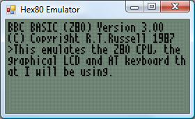
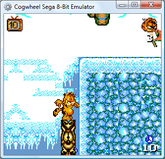
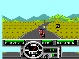
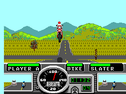
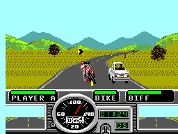
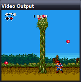
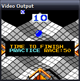
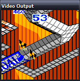
That's very well for life on real hardware, but I continue to do most of my development testing in an emulator. I'm having to use my own emulator as there aren't any other Master System emulators that also include a PS/2 keyboard emulator, but I did end up running into a very weird bug. Certain trigonometric functions in BBC BASIC were producing very wrong values, resulting in very odd-looking output.

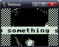
These shapes are on the wonk
Even though the Z80 emulator at the heart of the program passed ZEXDOC (an instruction tester that checks documented functionality) I remembered that it had failed some aspect of ZEXALL which checks the undocumented flags too. I re-ran ZEXALL and found the problem was with my implementation of the bit instruction, so I worked on fixing that including emulation of the Z80's internal temporary memptr/WZ register to ensure that bit n,(hl) set bits 3 and 5 of the flag register appropriately. ZEXALL now passes, but unsurprisingly it didn't fix my problem (as I didn't really think that BBC BASIC would rely on undocumented functionality!)
I ended up isolating certain exact values that when plugged into SIN() or COS() would produce incorrect results. I then dug out my old CP/M emulator and tried plugging those values into the generic CP/M version of BBC BASIC (which has none of my code in it!) and that produced the same, incorrect, results confirming that the issue was definitely in my Z80 emulation and not in some flaw of the BBC BASIC port.
After tracing through the code and dumping out debug values at certain points and seeing where it differed to a known good reference emulator I found that the fault occurred in FMUL, and from there I found that at some point the carry flag (which is either rotated or added to registers with RR or ADC instructions) was being lost. RR looked fine but digging into my implementation for the 16-bit ADC I found the culprit: the code is the same for ADD and ADC, but in ADC if the carry flag is set then the second operand is incremented by one first. This produces the correct numeric answer, but if the second operand was $FFFF on entry to the function then adding a carry of 1 to it would cause it to overflow back to 0. As this happens before any of the rest of the calculations are made it means that the final value of the carry flag was calculated based on op1+0 instead of op1+$10000, hence the loss of the carry flag.
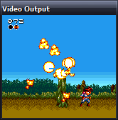
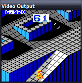
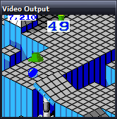
Fortunately, fixing this fixed the wonky output demonstrated above and I feel slightly more confident in my emulation! Now I can continue working on BBC BASIC, I've had an idea for a screen mode that has a reduced number of colours but will hopefully let you draw anywhere on the screen without running out of tiles causing odd corruption (as happens in the usual 16-colour mode 4) and without attribute clash (as happens in the TMS9918A Graphics II mode)...
Emulators and neatened wiring
Tuesday, 12th August 2008
I've decided to switch to a regular 10MHz Z80 rather than a Z180, given the difficulty of using an SDIP 64. I now have a DIP 40 Z80 ready for use, but as I don't have the programmer for the Flash chip (which will hold the OS) there's not much I can do with it physically. I have therefore cobbled together a basic emulator to help develop some of the software beforehand.
To cut hardware costs I'm going to try and handle input in software. One bit of hardware I'm planning on having is an eight-bit open collector I/O port. Open collector pins float high in their reset state, and any device connected to the pin can drive it low. AT devices (keyboard and mouse) use this type of electrical connection, as does the I2C bus and the TI calculator link port. I can use up the eight pins easily - two pins per AT device (keyboard and mouse) makes four, two pins for the I2C bus and two pins for a TI calculator link port.
The I2C bus I mentioned above is a simple way to enhance the computer once built. There will be one device permanently attached to the bus, a DS1307 real-time clock, which will be used to provide time-keeping functions for the OS as well as generating periodic interrupts (the chip could be configured to trigger an interrupt 100 times a second, useful for timing game logic). I could then leave empty space on the circuit board to add other I2C devices over time, or have a socket on the case that could be used to plug in additional I2C modules.
Now that I have some more tools, namely a desoldering pump, I tidied up the horrible hack job I'd done on the graphical LCD (replacing the multiple wires with a single pin header).
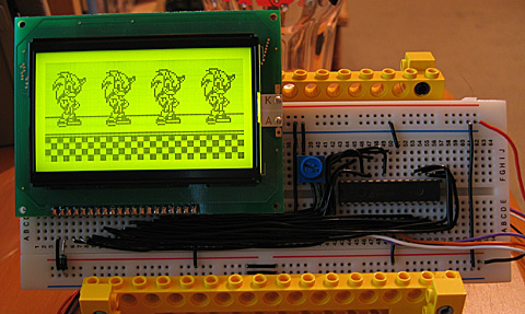
Yes, still the PICAXE here, but I'm using its 256 byte EEPROM to store a 32×64 pixel image of Sonic that is repeated four times horizontally.
I'm still not sure what I'm doing with regards to memory or storage. I'm still working on the simple assumption that ROM is 32KB ($0000..$7FFF) and RAM is 32KB ($8000..$FFFF) but this wastes a lot of memory and isn't very flexible at all. I've planned a bank-switching MMU, but as this will require at least four registers to store what appears in each of the four 16KB windows it will end up being physically very large and painful to wire.
As for storage, I have no idea. I have some 32KB I2C EEPROMs, but 32KB isn't exactly very large. Alternatively, I have an old 512MB SD card, and could try talking to it over bit-banged SPI. (SD cards use 3.3V, though, which complicates matters - not to mention that bit-banged SPI is going to be a little sluggish). I also have a USB module which can talk to USB mass storage devices over a serial connection, so maybe I should add a UART to the project. Adding a fully-blown USB module (which also plays WMA, MP3 and MIDI files) to such an otherwise low-tech computer feels like heresy, though.
Z80 BBC BASIC - Emulated on Windows
Thursday, 22nd May 2008
I've started working with the actual BBC BASIC interpreter. As it won't run in its current state on the TI calculator (it relies on a jump table at &FF80..&FFFF to interact with the host, which is protected) I'm using the Z80 emulator I wrote for Cogwheel to try and puzzle out what the host interface should be doing from the relative sanity of C# code (the jump table is populated with OUT (n), A instructions which are subsequently trapped and handled by the emulator).
One thing I hadn't realised is that the graphics operations that BBC BASIC offers are actually implemented via the OSWRCH handler (OS WRite CHaracter), which means that BBC BASIC's PLOT, MOVE and DRAW commands will also be available, as well as any commands that use them indirectly (such as CIRCLE).
Necromancy
Friday, 8th February 2008
After seeing Scet and Drilian's work on their respective emulator projects I decided I needed to do something with the stagnating Cogwheel source on my hard disk drive.
The only ROM I have tested where I can't find an explanation for a bug is the Game Gear Garfield: Caught in the Act game. Like many games, when left at the title screen it'll run a demo loop of the game in action. At one point Garfield would walk to the left of the screen, jump over a totem pole, shunt it to the right and use it as a way to jump out of a pit. However, in Cogwheel he would not jump far enough to the left, and not clearing the totem pole he'd just walk back to the right and not have anything to jump out of the pit on.
I remembered a post on MaxCoderz discussing a long-standing tradition of thinking that when a JP <condition>, <address> failed the instruction took a single clock cycle. You can see this misreported here, for example. This document, on the other hand, claims it always takes 10 clock cycles - and most importantly of all, the official user manual backs this up.
So, Garfield can now get out of his pit. The user interface has changed (again) - I'm now using SlimDX to dump pixels to a Panel, which seems to be the least hassle distribution-wise and doesn't throw LoaderLockExceptions.
Emulating TI-OS 1.15 and a greyscale LCD
Monday, 29th October 2007
OS 1.15 appears to boot, and if I run an OS in Pindur TI, archive the files (copy them to Flash ROM) then use that ROM dump in my emulator the files are still there, where they can be copied to RAM.
Trying to re-archive them results in a fairly un-helpful message, as I haven't implemented any Flash ROM emulation (nor can I find any information on it)...
Applications (which are only ever stored and executed on Flash ROM) work well, though.

I've also updated the LCD emulation a little to simulate the LCD delay; greyscale programs (that flicker pixels on and off) work pretty well now.


Brass 3 and TI-83+ Emulation
Friday, 26th October 2007
Brass 3 development continues; the latest documentation (automatically generated from plugins marked with attributes via reflection) is here. The compiler is becoming increasibly powerful - and labels can now directly store string values, resulting in things like an eval() function for powerful macros (see also clearpage for an example where a single function is passed two strings of assembly source and it uses the smallest one when compiled).
Thanks to a series of hints posted by CoBB and Jim e I rewrote my TI-83+ emulator (using the SMS emulator's Z80 library) and it now boots and runs pretty well. The Flash ROM archive isn't implemented, so I'm stuck with OS 1.12 for the moment (later versions I've dumped lock up at "Defragmenting..."). I also haven't implemented software linking, and so to transfer files I need to plug in my real calculator to the parallel port and send files manually.
Quake 2 and Emulation
Wednesday, 1st August 2007
The current design of the Quake project is that there are a bunch of classes in the Data namespace that are used to decode Quake's structures in a fairly brain-dead manner. To do anything useful with it you need to build up your own structures suitable for the way you intend on rendering the level.
The problem comes in when you try to load resources from different versions of Quake. Quake 1 and Quake 2 have quite a few differences. One major one is that every BSP level in Quake contains its own mip textures. You can call a method in the BSP class which returns sane texture coordinates as it can inspect the texture dimensions inside itself. Quake 2 stores all of the textures externally in .wal resources - the BSP class can no longer calculate texture coordinates as it can't work out how large the textures are as it can't see outside itself.
I guess the only sane way to work this out is to hide the native types from the end user and wrap everything up, but I've never liked this much as you might neglect to wrap up something that someone else would find very important, or you do something that is unsuitable for the way they really wanted to work.
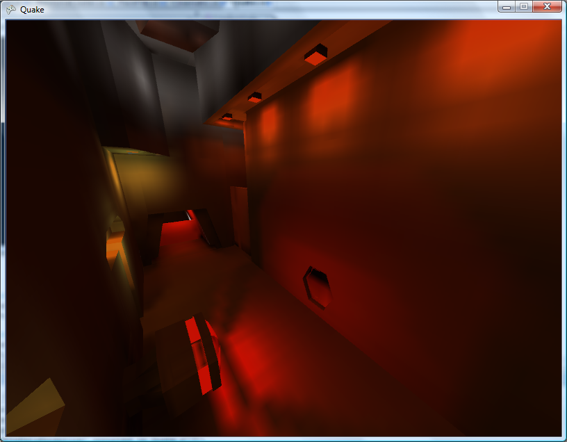
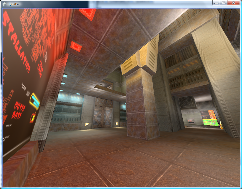
Anyhow. I've hacked around the BSP loader to within an inch of its life and it seems to be (sort of) loading Quake 2 levels for brute-force rendering. Quake 2 boasts truecolour lightmaps, improving the image quality quite significantly!
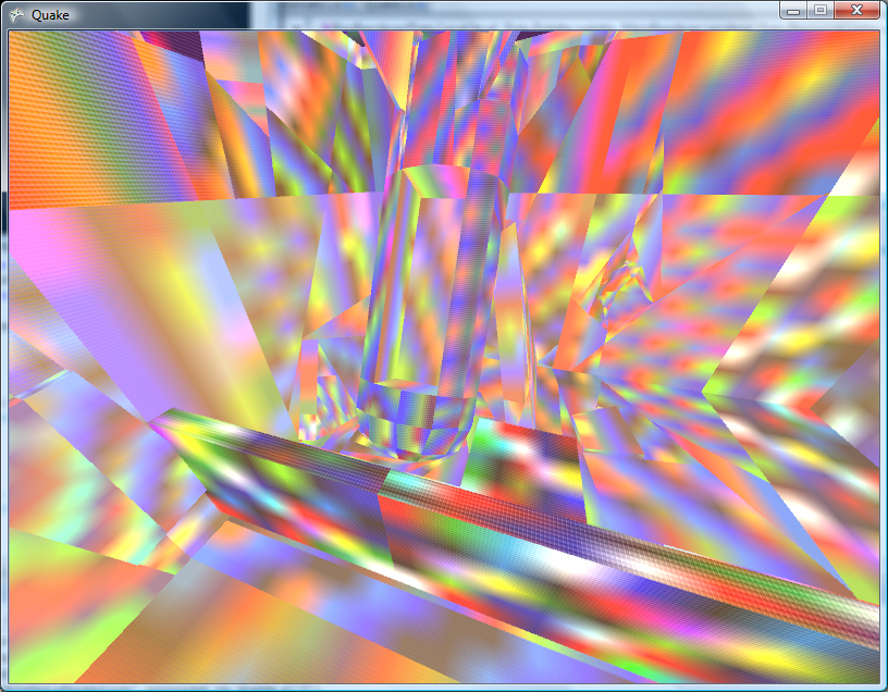
The truecolour lightmaps show off the Strogg disco lighting to its best effect. One of the problems with the Quake II BSP file format is that the indexing of lumps inside the file has changed. Not good.
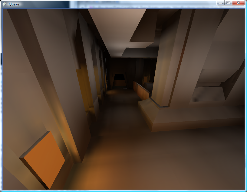
That's a bit better.  Quake II's lightmaps tend to stick to the red/brown/yellow end of the spectrum, but that is a truecolour set of lightmaps in action!
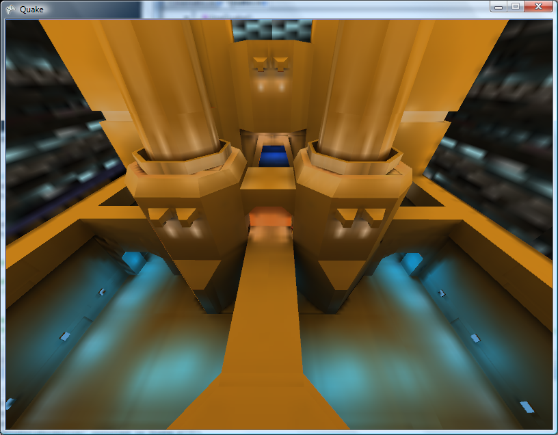
The lightmaps tend to look a bit grubby where they don't line up between faces. Some trick to join all lightmaps for a plane together into a single texture should do the trick, and reduce the overhead of having to load thousands of tiny textures (which I'm guessing have to be scaled up to a power-of-two). I'll have to look into it.
On to .wal (wall texture) loading - and I can't find a palette anywhere inside the Quake II pack files. I did find a .act (Photoshop palette) that claimed to be for Quake II, but it doesn't quite seem to match. It's probably made up of the right colours, but not in the right order.
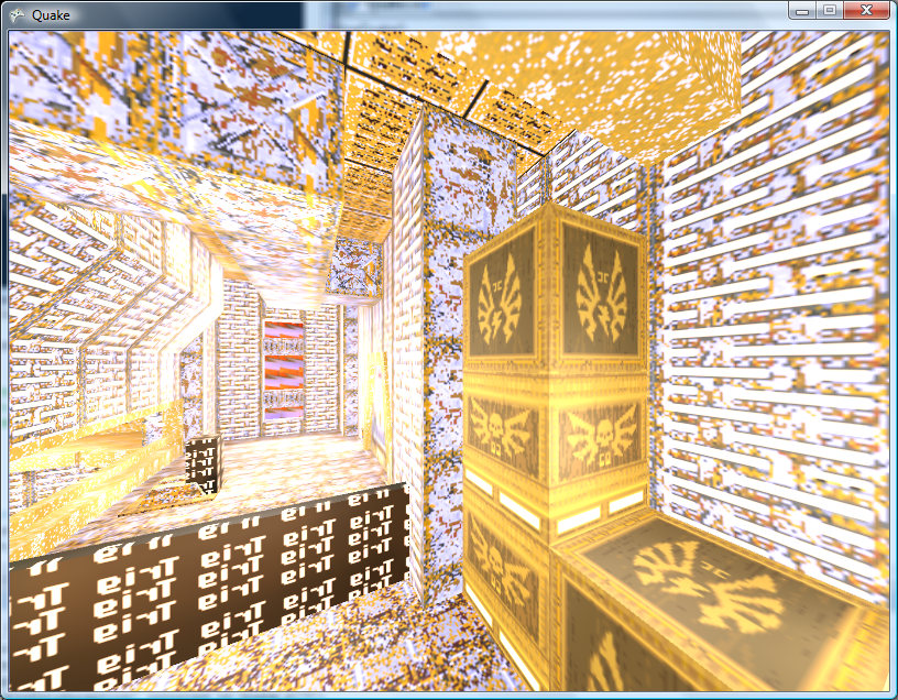
Fortunately I have some PAK files with replacement JPEG textures inside them and can load those instead for the moment.

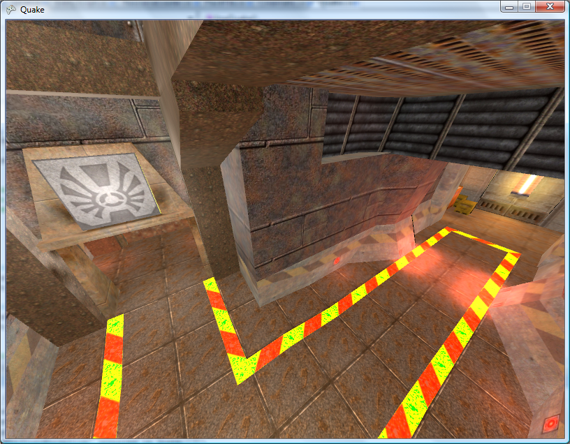
The brightness looks strange due to the bad way I apply the lightmaps - some kludgy forced two-pass affair with alpha blending modes set to something that sort of adds the two textures together in a not-very-convincing manner.
Can anyone recommend a good introduction to shaders for XNA? I'm not really trying to do anything that exciting.
This is a really bad and vague overview of the emulation technique I use in Cogwheel, so I apologise in advance. Emulation itself is very simple when done in the following manner - all you really need is a half-decent knowledge of how the computer you're emulating works at the assembly level. The following is rather Z80-specific.
At the heart of the system is its CPU. This device reads instructions from memory and depending on the value it reads it performs a variety of different actions. It has a small amount of memory inside itself which it uses to store its registers, variables used during execution. For example, the PC register is used as a pointer to the next instruction to fetch and execute from memory, and the SP register points at the top of the stack.
It can interact with the rest of the system in three main ways:
- Read/Write Memory
- Input/Output Hardware
- Interrupt Request
I assume you're familiar with memory. The hardware I refer to are peripheral devices such as video display processors, keypads, sound generators and so on. Data is written to and read from these devices on request. What the hardware device does with that data is up to it. I'll ignore interrupt requests for the moment.
The CPU at an electronic level communicates with memory and hardware using two buses and a handful of control pins. The two buses are the address bus and data bus. The address bus is read-only (when viewed from outside the CPU) and is used to specify a memory address or a hardware port number. It is 16 bits wide, meaning that 64KB memory can be addressed. Due to the design, only the lower 8-bits are normally used for hardware addressing, giving you up to 256 different hardware devices.
The data bus is 8-bits wide (making the Z80 an "8-bit" CPU). It can be read from or written to, depending on the current instruction.
The exact function of these buses - whether you're addressing memory or a hardware device, or whether you're reading or writing - is relayed to the external hardware via some control pins on the CPU itself. The emulator author doesn't really need to emulate these. Rather, we can do something like this:
class CpuEmulator {

	public virtual void WriteMemory(ushort address, byte value) {
		// Write to memory.
	}

	public virtual byte ReadMemory(ushort address) {
		// Read from memory.
		return 0x00;
	}

	public virtual void WriteHardware(ushort address, byte value) {
		// Write to hardware.
	}

	public virtual byte ReadHardware(ushort address) {
		// Read from hardware.
		return 0x00;
	}

}
A computer with a fixed 64KB RAM, keyboard on hardware port 0 and console (for text output) on port 1 might look like this:
class SomeBadComputer : CpuEmulator {

	private byte[] AllMemory = new byte[64 * 1024];

	public override void WriteMemory(ushort address, byte value) {
		AllMemory[address] = value;
	}

	public override byte ReadMemory(ushort address) {
		return AllMemory[address];
	}

	public override void WriteHardware(ushort address, byte value) {
		switch (address & 0xFF) {
			case 1:
				Console.Write((char)value);
				break;
		}
	}

	public override byte ReadHardware(ushort address) {
		switch (address & 0xFF) {
			case 0:
				return (byte)Console.ReadKey();
			default:
				return 0x00;
		}
	}

}
This is all very well, but how does the CPU actually do anything worthwhile?
It needs to read instructions from memory, decode them, and act on them. Suppose our CPU had two registers - 16-bit PC (program counter) and 8-bit A (accumulator) and this instruction set:
00nn   : Load 'nn' into accumulator.
01nn   : Output accumulator to port N.
02nn   : Input to accumulator from port N.
03nnnn : Read from memory address nnnn to accumulator.
04nnnn : Write accumulator to memory address nnnn.
05nnnn : Jump to address nnnn.
Extending the above CpuEmulator class, we could get something like this:
partial class CpuEmulator {

	public ushort RegPC = 0;
	public byte RegA = 0;

	private int CyclesPending = 0;

	public void FetchExecute() {
		switch (ReadMemory(RegPC++)) {
			case 0x00:
				RegA = ReadMemory(RegPC++);
				CyclesPending += 8;
				break;
			case 0x01:
				WriteHardware(ReadMemory(RegPC++), RegA);
				CyclesPending += 8;
				break;
			case 0x02:
				RegA = ReadHardware(ReadMemory(RegPC++));
				CyclesPending += 16;
				break;
			case 0x03:
				RegA = ReadMemory((ushort)(ReadMemory(RegPC++) + ReadMemory(RegPC++) * 256));
				CyclesPending += 16;
				break;
			case 0x04:
				WriteMemory((ushort)(ReadMemory(RegPC++) + ReadMemory(RegPC++) * 256), RegA);
				CyclesPending += 24;
				break;
			case 0x05:
				RegPC = (ushort)(ReadMemory(RegPC++) + ReadMemory(RegPC++) * 256);
				CyclesPending += 24;
				break;
			default:
				// NOP
				CyclesPending += 4;
				break;
		}
	}

}
The CyclesPending variable is used for timing. Instructions take a variable length of time to run (depending on complexity, length of opcode, whether it needs to access memory and so on). This time is typically measured in the number of clock cycles taken for the CPU to execute the instruction.
Using the above CyclesPending += x style one can write a function that will execute a particular number of cycles:
partial class CpuEmulator {

	public void Tick(int cycles) {
		CyclesPending -= cycles;
		while (CyclesPending < 0) FetchExecute();
	}

}
For some truly terrifying code, an oldish version of Cogwheel's instruction decoding switch block. That code has been automatically generated from a text file, I didn't hand-type it all.
Um... that's pretty much all there is. The rest is reading datasheets! Your CPU would need to execute most (if not all) instructions correctly, updating its internal state (and registers) as the hardware would. The non-CPU hardware (video processor, sound processor, controllers and so on) would also need to conform to data reads and writes correctly.
As far as timing goes, various bits of hardware need to run at their own pace. One scanline (of the video processor) is a good value for the Master System. Cogwheel provides this method to run the emulator for a single frame:
public void RunFrame() {
	this.VDP.RunFramePending = false;
	while (!this.VDP.RunFramePending) {
		this.VDP.RasteriseLine();
		this.FetchExecute(228);
	}
}
In the Master System's case, one scanline is displayed every 228 clock cycles. Some programs update the VDP on every scanline (eg changing the background horizontal scroll offset to skew the image in a driving game).
The above is embarrassingly vague, so if anyone is interested enough to want clarification on anything I'd be happy to give it.
TI Emulation, Functions in Brass and Gemini on the Sega Game Gear
Tuesday, 13th February 2007
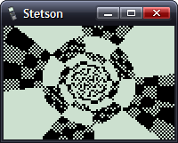
This post got me wondering about a TI emulator. I'd rather finish the SMS one first, but so as to provide some pictures for this journal I wrote a T6A04 emulator (to you and me, that's the LCD display driver chip in the TI-82/83 series calculators). In all, it's less than a hundred lines of code.
The problem with TI emulation is that one needs to emulate the TIOS to be able to do anything meaningful. Alas, I had zero documentation on the memory layout of the TI calculators, and couldn't really shoe-horn the ROM dump into a 64KB RAM, so left it out entirely. That limits my options as to what I can show, but here's my Microhertz demo -
I've added native support for functions in Brass.
The old Brass could do some function-type things using directives; for example, compare the two source files here:
.fopen fhnd, "test.txt"          ; Opens 'test.txt' and stores a handle in fhnd
.fsize fhnd, test_size           ; Stores the size of the file in test_size

.for i, 1, test_size
    .fread fhnd, chr             ; Read a byte and store it as "chr"
    .if chr >= 'a' && chr <= 'z' ; Is it a lowercase character?
        .db chr + 'A' - 'a'
    .else
        .db chr
    .endif
.loop

.fclose fhnd                      ; Close our file handle.
I personally find that rather messy. Here's the new version, using a variety of functions from the 'File Operations' plugin I've been writing:
fhnd = fopen("test.txt", r)

#while !feof(fhnd)
    chr = freadbyte(fhnd)
    .if chr >= 'a' && data <= 'z'
        .db chr + 'A' - 'a'
    .else
        .db chr
    .endif
#loop

fclose(fhnd)
I find that a lot more readable.
An extreme example is the generation of trig tables. Brass 1 uses a series of directives to try and make this easier.
.dbsin angles_in_circle, amplitude_of_wave, start_angle, end_angle, angle_step, DC_offset
Remembering that is not exactly what I'd call easy. If you saw the line of code:
.dbsin 256, 127, 0, 63, 1, 32
...what would you think it did? You'd have to consult the manual, something I'm strongly opposed to. However, this code, which compiles under Brass 2, should be much clearer:
#for theta = 0, theta < 360, ++theta
    .db min(127, round(128 * sin(deg2rad(theta))))
#loop
By registering new plugins at runtime, you can construct an elaborate pair of directives - in this case .function and .endfunction - to allow users to declare their own.
_PutS = $450A

.function bcall(label)
    rst $28
    .dw label
.endfunction

bcall(_PutS)
You can return values the BASIC way;
.function slow_mul(op1, op2)
    slow_mul = 0
    .rept abs(op1)
        .if sign(op1) == 1
            slow_mul += op2
        .else
            slow_mul -= op2
        .endif
    .loop
.endfunction

.echo slow_mul(log(100, 10), slow_mul(5, 4))
I had a thought (as you do) that it would be interesting to see how well a TI game would run on the Sega Master System. After all, they share the CPU, albeit at ~3.5MHz on the SMS.
However, there are some other differences...
- Completely different video hardware.
- Completely different input hardware.
- 8KB RAM rather than 32KB RAM.
- No TIOS.
The first problem was the easiest to conquer. The SMS has a background layer, broken up into 8×8 tiles. If I wrote a 12×8 pattern of tiles onto the SMS background layer, and modified the tile data in my own implementation of _grBufCpy routine, I could simulate the TI's bitmapped LCD display (programs using direct LCD control would not be possible).
You can only dump so much data to the VRAM during the active display - it is much safer to only write to the VRAM outside of the active display period. I can give myself a lot more of this by switching off the display above and below the small 96×64 window I'll be rendering to; it's enough to perform two blocks, the left half of the display in one frame, the right in the next.
As for the input, that's not so bad. Writing my own _getK which returned TI-like codes for the 6 SMS buttons (Up, Down, Left, Right, 1 and 2) was fine, but games that used direct input were a bit stuck. I resolved this by writing an Out1 and In1 function that has to be called and simulates the TI keypad hardware, mapping Up/Down/Left/Right/2nd/Alpha to Up/Down/Left/Right/1/2.
The RAM issue can't be resolved easily. Copying some chunks of code to RAM (for self-modifying reasons) was necessary in some cases. As for the lack of the TIOS, there's no option but to write my own implementation of missing functions or dummy functions that don't do anything.
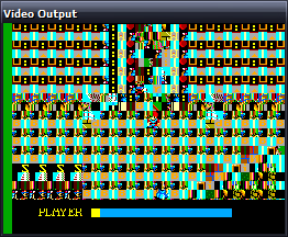
Even with the above, it's still not perfect. If I leave the object code in Gemini, the graphics are corrupted after a couple of seconds of play. I think the stack is overwriting some of the code I've copied to RAM.
No enemies make it a pretty bad 'game', but I thought it was an entertaining experiment.
Sega BASIC
Monday, 8th January 2007
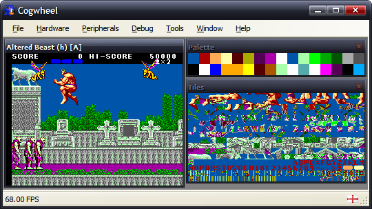
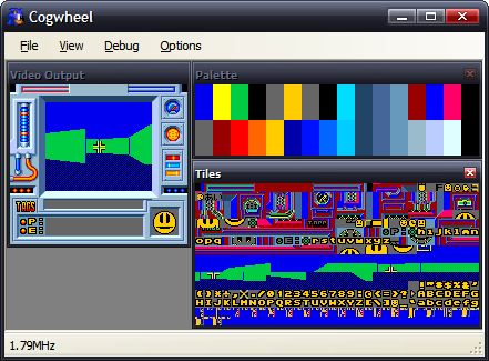
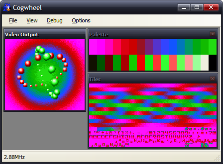
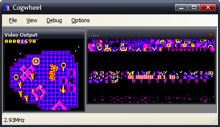
I have returned to the MDI view for this project which makes life easier when it comes to putting in debugging tools. For the moment all there is is a palette and tile viewer, but I hope to add some helpful utilities - and work out a way to tie the new Brass and an emulator together for debugging assembly programs.
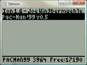
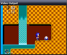
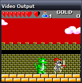
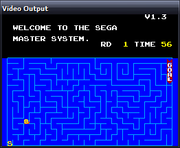
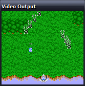
I've extended the SG-1000 emulation some way towards the SC-3000 (Sega Game 1000 vs. Sega Computer 3000) which has mainly involved adding keyboard emulation. The result is the ability to run Sega BASIC, and so you get the obligatory program that everyone writes sooner or later...
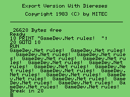
There is no tape drive emulation, and I'd like to ideally emulate the SF-7000's floppy drive and disk BASIC, but don't quite follow the datasheets I've read thus far (or rather, how everything is tied together).
In the first screenshot you might have noticed that the video output window has "Altered Beast (h) [A]" in the caption. I've added ROM library support, and am currently using the data from the .romdata files arranged by Maxim for his SMS Checker utility. As well as identify a name, there is a more important reason to use the database - it can identify dodgy dumps and be used to correct them (in this case, Altered Beast has an additional header - hence the (h) - that needs to be removed).
SG-1000
Wednesday, 3rd January 2007
I've added some support for the SG-1000, Sega's first? home video game console.

The Master System's VDP is a modified TMS9918, and so most Master System games run in its extended 'Mode 4' setting. That was the only video mode, therefore, that I'd emulated in any form.
For some reason, the older computer games are, the more charm they seem to have to me (maybe because the first games I played would have been on a BBC Micro, which certainly looked a lot more primitive than the Master System games I've been attempting to emulate thus far). I dug out TI's TMS9918 documentation - the differences are quite significant! Tiles are monochrome (though you can pick which foreground and background colour is in use - to some extent), the palette is fixed to 16 pre-defined colours (one of which being 'transparent') and sprite sizes and collisions are handled differently. Various features found in the Master System's VDP (scrolling, line-based interrupts) also appear to be missing from the 'vanilla' TMS9918, but I'm not sure whether or not they make an appearance in the SMS variation of the VDP or not, along with the original TMS9918 limitations.
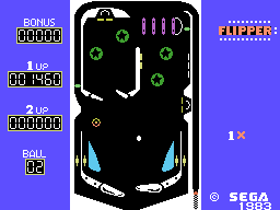
Flipper
At any rate, the emulator now has a 'SG-1000' mode. The only differences at the moment are that the TMS9918 palette is used and line interrupts are disabled, so you can still (for example) use mode 4 on it.
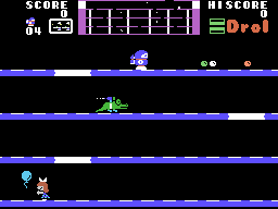
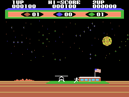

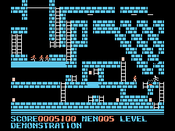
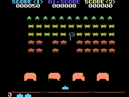
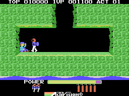
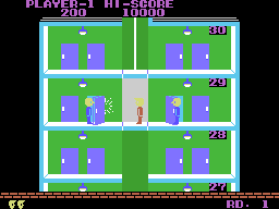
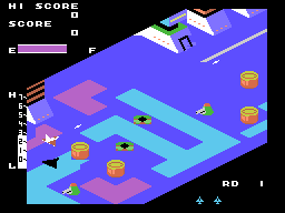
From first to last: Drol, Choplifter, Hustle Chummy, Championship LodeRunner, Space Invaders, H.E.R.O., Elevator Action, and Zaxxon.
All but one of the SG-1000 games I had ran - and that was The Castle. According to meka.nam, this has an extra 8KB of onboard RAM. Whilst doing some research into the SG-1000 and the TMS9918, I found a forum post by Maxim stating "The Castle runs nicely on my RAM cart :)". Enter the new ROM mapper option to complement Standard, Codemasters and Korean - it's the RAM mapper, which simply represents the entire Z80 address range with a 64KB RAM.
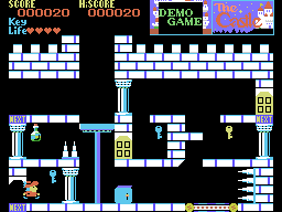
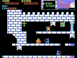
That seems to have done the trick!
I mentioned that the palette was different in the SMS VDP and the original TMS9918 - here's an example (SMS on the left, SG-1000 on the right):


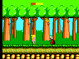
I'm assuming this is the result of truncating the TMS9918 palette to the SMS 6-bit palette without needing to implement two palette modes on the new VDP. Another comparison is between two versions of Wonder Boy - SMS on the left again, SG-1000 on the right:
VDP Interrupts
Wednesday, 20th December 2006
The VDP can generate two different types of CPU interrupt.
The first, and easiest, is the frame interrupt, which is requested when an entire frame has been generated. This is requested, therefore, at a regular 60Hz in NTSC regions and 50Hz in PAL regions - it's a useful timer to synchronise your game to.
The second, and more complex, is the line interrupt. This interrupt is requested when a user-definable number of scanlines have been displayed. An internal counter is decremented each active line (and one more just after), and when it overflows it resets to the value held in a VDP register and requests the interrupt (so 0 would request an interrupt every line, 1 every other line and so on). For every other line outside the active display area, the counter is reset to the contents of the VDP register.
Both interrupt types can be enabled or disabled by defined bits held in the VDP registers.
(The above should be loosely correct, the below is a little more uncertain).
Once an interrupt is requested, a flag for said interrupt is set. The flag is not reset until the VDP control port is read, so you must read the VDP control port if you expect any further interrupts.
To differentiate between line and frame interrupts you can check the value read from the control port. If the most significant bit is set, a frame interrupt (at least) was requested. Reading the vertical counter port (which returns the current scanline's vertical position) will also let you know where you are.
Something is a little wonky with my vertical counting code, as all lines end up being one too large. For the moment I'm subtracting one before returning the value (and waiting one extra scanline before triggering the frame interrupt) which is a horrible solution, but for the moment it has fixed a number of games that weren't working at all before.
Earthworm Jim, which relies on line interrupts to switch on zoomed sprites to dipslay the status bar at the bottom, now plays. It's missing some graphics on the title screens, though.
For some reason, rebuilding my Z80 emulator (which is in a different project) fixed some other interrupt-related glitches, so I have a sneaking suspicion most of my earlier problems are related to using an out-of-date DLL.
Road Rash highlighted another bug. The VDP can draw doubled sprites - that is, when a particular bit is set it will draw sprites as 8x16 pixels, stacking two consecutive sprite tiles on top of each other. Road Rash uses this mode, but also uses odd sprite indices (odd as opposed to even, not strange). The VDP will only take even indices, so a line of code to clear the least significant bit if using doubled sprites fixed that.
Still no sound, though.
Real 3D on classic 2D hardware
Monday, 18th December 2006
My existing implementation of the standard mapper used the values $1FFC..$1FFF in RAM as the paging registers. This is incorrect; from what I can now tell the paging registers are only updated if you write to the $FFFC..$FFFF range, and isn't anything to do with the RAM anyway (the fact that they end up in RAM is a side-effect, not the main way of doing things).
Updating my code to handle this, rather than using the values in RAM, fixed some games; notably Phantasy Star and Space Harrier.
Thanks to Maxim's post, I fixed the Codemasters mapping for the Excellent Dizzy Collection:
A fun bit of hardware is the 3D glasses. These LCD shutter glasses could be used with certain games, and are controlled by writing to the memory range $FFF8..$FFFB. The least-significant bit controls which shutter is open and which is shut, and by alternating frames rapidly in time with the shutters you can display two views; one for the left eye, one for the right.
I've added four different 3D glasses mode. No effect doesn't do anything special, so you just get an unsightly flickery view. Frozen displays frames for one eye only, giving you a 2D view of the 3D game.
To recreate the 3D view on your PC, though, there are two methods. The first method is the standard red-green anaglyph view, for use with those red-green glasses:
Unfortunately, on top of the usual shimmery view you get from anaglyphs, this is made even worse by the fact that I don't remove the existing colour information from the frames. This looks nicer without glasses, but looks really quite horrible when viewed (as intended) through the glasses. For example, the red text is invisible through the green filter, but strongly visible through the red filter, making it shimmer.
By sacrificing the colour and only taking the luminance of the orignal frames, you get an anaglyph that remains stable when viewed.
Fortunately, there is an easy way to retain full colour information in a 3D image, which is to use a stereo pair.
The image on the left is to be viewed by your right eye, and the one on the right by your left eye. If you cross your eyes until the two images overlap, and concentrate on the middle one, you should be able to focus on a 3D image.
I tried adding sound emulation back in, but the timing has confused me once more. If you can help, I've posted the relevant thread here.
Turning Japanese
Friday, 15th December 2006
The Z80 CPU uses 16-bit addressing, which limits it to a 64KB address space. As well as fitting the program ROM into this space, we need to fit in the machine's 8KB RAM, limiting us even further.
To get around this limitation, the memory is broken down into a series of windows ("frames"), and you can change what is visible in some of these windows.
The memory range $C000..$DFFF can be used to address the 8KB RAM. This is mirrored from $E000..$FFFF; that is, reads and writes to $E000 work as if you were reading and writing to $C000.
There are three other windows; from $0000..$3FFF, $4000..$7FFF and $8000..$BFFF. By changing the contents of RAM (addresses $FFFC..$FFFF) you can adjust what is accessible from these memory ranges.
The lower 1KB cannot be paged out - this is because when the device boots the contents of RAM (and thus paging registers) are undefined, and you need something fixed in place to set up the machine correctly.
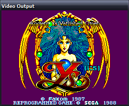
I had already implemented most of the above, with two omissions. The first was that certain cartridges contained their own additional RAM chips (accessible by setting flag bits in paging register $FFFC) that could be used as saved game area. Ys appears to use this area, and so didn't work without it. That was the garbled screenshot I posted earlier:
The Flash now works too.
The second omission was that Codemasters games use a different mapping system to the standard one. Fortunately it is significantly simpler; the 32KB from $0000..$7FFF is locked, and the 16KB from $8000..$BFFF is offset based on a value previously written to address $8000. ($C000..$FFFF is 8KB work RAM as usual).
The Excellent Dizzy Collection as seen at the top of this post doesn't entirely work; when you pick a game it resets. Some other emulators do this too. The Game Gear games Cosmic Spacehead and Micro Machines (1 and 2) work well, though.
After some fiddling around with the VDP emulation and interrupts, some more games work (but I'm not sure why they now work):
Other parts of the emulator have been improved. It can now be set to either domestic (Japanese) or export (everyone else) modes, which affects some games in a variety of ways - from translated text, to removing the Mark III bumper screen, to changing the title of the game.
For Game Gear games, detecting whether it's a Japanese machine or not is simple - test the 6th bit returned when you read port $00. If it's set, you've got an export machine.
However, port $00 is Game Gear-specific - the Master System hardware has a peculiarity that is used to detect region. There are two ports for controllers, and each controller has up, down, left, right, TL, TR and TH lines. You can set the TR and TH lines to be inputs or outputs (and the output level if configured as output) by writing to the I/O control port. If you set them to outputs and try and read from them, on export hardware you get the values you are telling them to output. On Japanese machines, however, they return 0s regardless of the chosen output level.
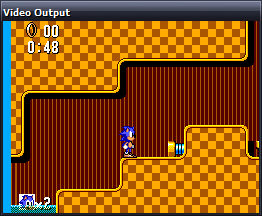
A more fun addition is Game Genie support. A simple call to Emulator.AddGameGenieCode("3A0-21C-2A2"); and Sonic can stand here all day:
Of course, the technical information above is my interpretation of what I've gathered so far from various documents from far brainier chaps than I, and the fact that all I have is a broken emulator indicates that it is probably complete rubbish.
New Z80 emulator
Wednesday, 6th December 2006
One chap I cannot thank enough is CoBB for all his hard work in the Z80 field.
I've rewritten the Z80 emulation from scratch; this time it uses an expanded switch block (the 'manual' way) to decode instructions. Rather than write every combination of instructions out by hand, the code making up the switch blocks up is generated by another program, reading instruction information from a table copied from an Excel spreadsheet.
At the cost of a significantly larger assembly (from 40KB to 140KB) I now get a 100% speed increase (from ~50MHz to 100MHz).
I still can't pass the port of ZEXALL I'm testing with (and the same instructions too - not bad for a 100% rewrite to end up with exactly the same bugs), but after comparing some of my offending tables against CoBB's ones I've isolated some of the hiccoughs. The only instruction group test I fail is, naturally, the one that takes the longest to execute - getting a hardware, or indeed emulator, comparison takes well over an hour.
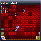
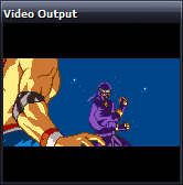
Anyhow, rewriting the Z80 emulation seems to have been the right thing to do. As you might have guessed from the picture at the top of this entry, Sonic now runs.
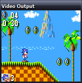
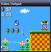
My VDP (Video Display Processor) emulation is still rather rough-and-ready (I've really been concentrating on the Z80 bit) and the second column of background tiles is not updated correctly, so I apologise in advance for the distortion! It only appears in SMS mode (the display is cropped in Game Gear mode).
The fill colour (in the left column here) is incorrect in most games too.
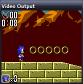
I rather preferred Sonic 2, but maybe that's because you can pick up dropped rings and I'm rather lousy at it otherwise.
I accused the previous Wonder Boy III shot of not reading the start button. Somehow I also failed to notice the missing sprites (clouds and main part of the castle), which was part of the main problem. It now appears to play well.
Support for zoomed sprites seems to be missing in some emulators (at least, the versions of Dega and Pastorama I have to hand), but I use them so implemented them to let my programs work when testing - it's nice to see a commerical game use them too!
Gunstar Heroes runs, but flickers and jumps (not the visible sprite 'flicker' in those screenshots) - some bug in my CPU interrupt handling or VDP interrupt generation.
Psycho Fox runs insanely fast - even faster than The Flash as seen to the right - making an already difficult game to control virtually impossible. I'm really not sure what could be causing that, but the enemy sprites sometimes flicker up and back down quickly, so it could be one of the remaining CPU bugs.
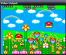
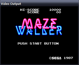
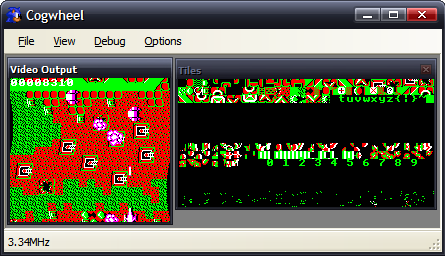
Fantasy Zone demonstrates both the blanking colour bug (that left column should be green) and the distorted second column bug, but plays well. I tried to get a better screenshot of Maze Walker, but not handling 3D glasses makes looking at the screen a rather unpleasant experience (it flickers the left and right eye views in quick succession; the 3D glasses had two LCD shutters that opened and closed in sequence with the images on-screen).
I might add a Dega-esque red/green anaglyph filter, but I find those rather unpleasant to look at so might provide a stereo pair view.
In any case, the most important SMS game now runs -
I shall refrain from using the Terry Pratchett quote (just this once).
Some games look like the above, which makes me happy - it's the ones that do nothing at all that worry me. What with the CPU bugs, dodgy emulation of the mapper, missing (important!) hardware ports and hackish VDP, it's surprising anything runs. It's getting better.
EDIT: How are there so many spelling errors? Fantasy Start as opposed to Fantasy Zone, Video Display Hardware as the expansion of the VDP acronym... I should not write these so late at night.
Compatibility increases further...
Thursday, 23rd November 2006
I've added better memory emulation (that is, handling ROM paging, RAM mirroring and enabling a BIOS or not). I wouldn't dare say "more accurate", as that might indicate that something about it is partially accurate.
I've isolated one of the biggest problems - and that's programs getting caught in a loop waiting for an interrupt that is never triggered.
The source of these interrupts is the VDP. It can generate two kinds of interrupt - on a line basis (where you can configure it to fire an interrupt every X scanlines) or on a frame basis (where it fires an interrupt at the end of the active display).
Two bits amongst the VDP's own registers control whether the interrupt fires or not. On top of that, there are two internal flags that are set when either of the interrupts fire. They are reset when the VDP's control port is read.
Bit 5 of register $01 acts like a on/off switch for the VDP's IRQ line. As long as bit 7 of the status flags [this is the frame interrupt pending flag] is set, the VDP will assert the IRQ line if bit 5 of register $01 is set, and it will de-assert the IRQ line if the same bit is cleared.
…
Bit 4 of register $00 acts like a on/off switch for the VDP's IRQ line. As long as the line interrupt pending flag is set, the VDP will assert the IRQ line if bit 4 of register $00 is set, and it will de-assert the IRQ line if the same bit is cleared.
The way I've chosen to emulate this is as a boolean storing the IRQ status, and to call a function, UpdateIRQ(), every time something that could potentially change the status of it happens.
private bool IRQ = false;
private void UpdateIRQ() {
    bool newIRQ = (LineInterruptEnabled && LineInterruptPending) || (FrameInterruptEnabled && FrameInterruptPending);
    if (newIRQ && !IRQ) this.CPU.Interrupt(true, 0x00);
    IRQ = newIRQ;
}
This detects a rising edge. Falling edge hasn't worked so well. Well, truth be told, neither work very well. So, hitting the I key in the emulator performs a dummy read of the control port which usually 'unblocks' the program.
I'm hoping that my problem is related to this similar one, as the fix seems pretty straightforwards.
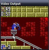
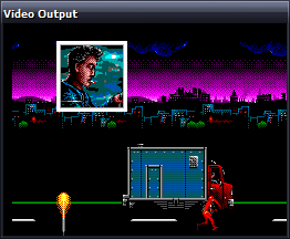
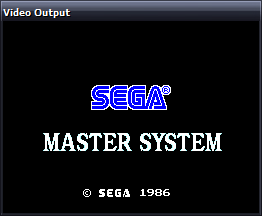
The SEGA logo at the top of this entry is not the only evidence of working commerical software...
Not reading the Start button is a common affliction.
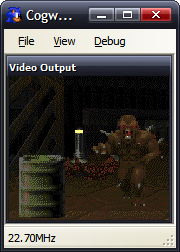
Here's the Game Gear DOOM for Scet.
Marble Madness appears to be fully playable, though needs prompting from my I key every so often.
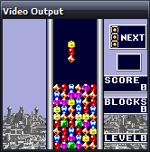
Columns can't find the start button either, but the demo mode works.
Getting as far as a title screen is still an achievement in my books.
My luck can't hold out forever, but the homebrew scene is still providing plenty of screenshots...
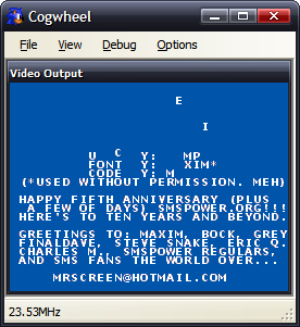
Maxim's Bock's Birthday 2002 has been immensely useful for sorting out ROM paging issues.
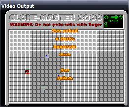
Bock's Birthday 2003 demonstrates the interrupt bug, but appears to run healthily otherwise.
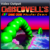
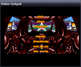
Chris Covell's Hicolor Demo also demonstrates this bug, needing a prod before each new image is displayed.
Aypok's Digger Chan appears to play fine.
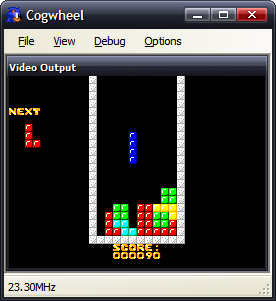
Martin Konrad's Zoop 'em Up and GG Nibbles games run, Zoop 'em Up seems to have collision detection issues (aluop-related bug).
The bug in the Z80 core still eludes me - how aluop with an immediate value passes and aluop with a register fails is rather worrying. At least part of the flags problem has been resolved - the cannon in Bock's KunKun & KokoKun still don't fire, but at the switches now work so you can complete levels.
Screenshots galore
Tuesday, 21st November 2006
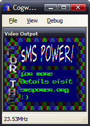
I downloaded a collection of homebrew releases from SMS Power! for testing. Here are the obligatory screenshots.
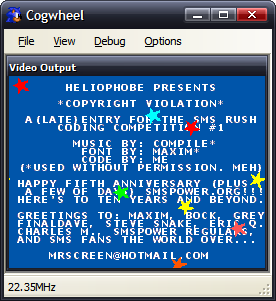
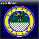
Copyright Violation is displayed incorrectly - the text should be on top of the stars, but that VDP feature is as yet unsupported.
Yes, Windows and DOOM were ported to the Game Gear. That second screenshot is DOOM's automap. 
There are still lots of ROMs that won't go - that could be due to poor VDP emulation, or it could be due to ROM paging errors (the emulated memory is just straight 64KB RAM), or could be down to the remaining bugs in the Z80 emulation.
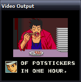
Sega: Enter the Pies
Monday, 20th November 2006
The Z80 core is now a bit more accurate - ZEXALL still reports a lot of glitches, and this is even a specially modified version of ZEXALL that masks out the two undocumented flags.
The VDP (Video Display Processor - the graphics hardware) has been given an overhaul and is now slightly more accurate. A lot more software runs now. I have also hacked in my PSG emulator (that's the sound chip) from my VGM player. It's not timed correctly (as nothing is!) but it's good enough for testing.
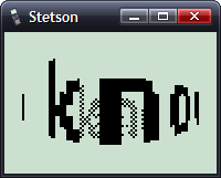
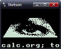
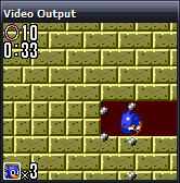
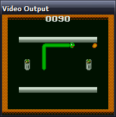
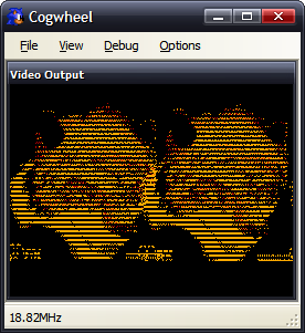
Picohertz, the demo I have been working on (on and off) now runs correctly. The hole in the Y in the second screenshot is caused by the 8 sprite per scanline limit. The first screenshot shows off sprite zooming (whereby each sprite is zoomed to 200% the original size). The background plasma is implemented as a palette shifting trick.
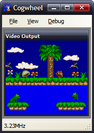
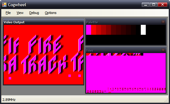
Fire Track runs and is fully playable. The second shot shows a raster effect (changing the horizontal scroll offset on each scanline.
Seeing as I understand the instructions that my programs use (and the results of them), and have my own understanding of parts of the hardware, it's not really surprising that the programs I've written work perfectly, but ones written by others don't, as they might (and often do) rely on tricks and results that I'm not aware of, or on hardware that I haven't implemented accurately enough. At least I do not need to emulate any sort of OS to run these programs!
SMS Power! has been an amazing resource in terms of hardware documentation and homebrew ROMs. I've been using the entries to the 2006 coding competition to test the emulator.
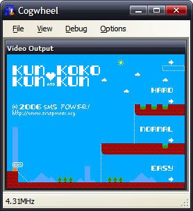
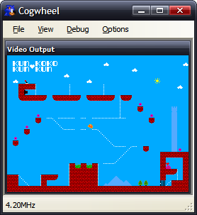
Bock's game, KunKun & KokoKun, nearly works. The cannon don't fire, which would make the game rather easy if it wasn't for the fact that the switch to open the door doesn't work either. I suspect that a CPU flag isn't being set correctly as the result to an operation somewhere.
Haroldoop's PongMaster is especially interesting as it was not written in Z80 assembly, but C. It's also one of the silkiest-smooth pong games I've come across.
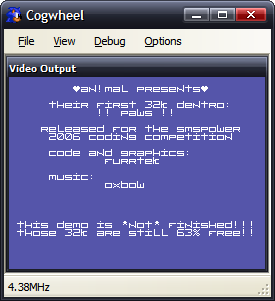
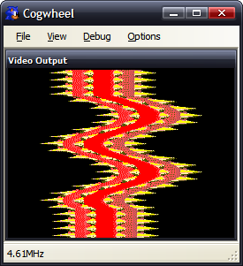
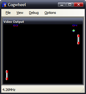
An!mal/furrtek's Paws runs, but something means that the effect doesn't work correctly (the 'wavy' bit should only have one full wave in it, not two - it appears my implementation of something doubles the frequency of the wave). The music sounds pretty good, though.
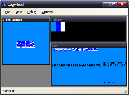
Sega's Columns gets the furthest of any official software - the Sega logo fades in then out.
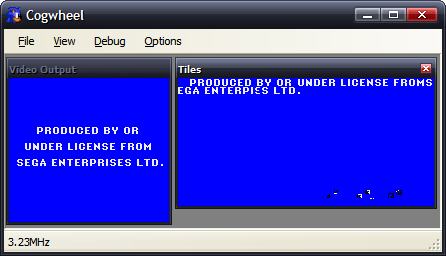
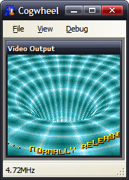
I do like the idea that Sega is an ENTERPIεS. (From the Game Gear BIOS). (I believe this is a CPU bug).
Charles Doty's Frogs is a bit of a conundrum. The right half of the second frog is missing due to the 8 sprites per scanline limitation of the VDP. However, Meka, Emukon, Dega and now my emulator draw the rightmost frog's tongue (and amount if it showing) differently, as well as whether the frog is sitting or leaping. There's a lot of source for such a static program (it doesn't do anything in any emulator I've tried it on, nor on hardware). Dega is by far the strangest, as the tongue moves in and out rapidly. I'm really not sure what's meant to be happening here.
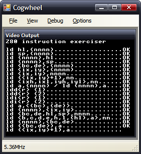
Here are the results of ZEXALL so far.
Z80 instruction exerciser

ld hl,(nnnn).................OK
ld sp,(nnnn).................OK
ld (nnnn),hl.................OK
ld (nnnn),sp.................OK
ld <bc,de>,(nnnn)............OK
ld <ix,iy>,(nnnn)............OK
ld <ix,iy>,nnnn..............OK
ld (<ix,iy>+1),nn............OK
ld <ixh,ixl,iyh,iyl>,nn......OK
ld a,(nnnn) / ld (nnnn),a....OK
ldd<r> (1)...................OK
ldd<r> (2)...................OK
ldi<r> (1)...................OK
ldi<r> (2)...................OK
ld a,<(bc),(de)>.............OK
ld (nnnn),<ix,iy>............OK
ld <bc,de,hl,sp>,nnnn........OK
ld <b,c,d,e,h,l,(hl),a>,nn...OK
ld (nnnn),<bc,de>............OK
ld (<bc,de>),a...............OK
ld (<ix,iy>+1),a.............OK
ld a,(<ix,iy>+1).............OK
shf/rot (<ix,iy>+1)..........OK
ld <h,l>,(<ix,iy>+1).........OK
ld (<ix,iy>+1),<h,l>.........OK
ld <b,c,d,e>,(<ix,iy>+1).....OK
ld (<ix,iy>+1),<b,c,d,e>.....OK
<inc,dec> c..................OK
<inc,dec> de.................OK
<inc,dec> hl.................OK
<inc,dec> ix.................OK
<inc,dec> iy.................OK
<inc,dec> sp.................OK
<set,res> n,(<ix,iy>+1)......OK
bit n,(<ix,iy>+1)............OK
<inc,dec> a..................OK
<inc,dec> b..................OK
<inc,dec> bc.................OK
<inc,dec> d..................OK
<inc,dec> e..................OK
<inc,dec> h..................OK
<inc,dec> l..................OK
<inc,dec> (hl)...............OK
<inc,dec> ixh................OK
<inc,dec> ixl................OK
<inc,dec> iyh................OK
<inc,dec> iyl................OK
ld <bcdehla>,<bcdehla>.......OK
cpd<r>.......................OK
cpi<r>.......................OK
<inc,dec> (<ix,iy>+1)........OK
<rlca,rrca,rla,rra>..........OK
shf/rot <b,c,d,e,h,l,(hl),a>.OK
ld <bcdexya>,<bcdexya>.......OK
<rrd,rld>....................OK
<set,res> n,<bcdehl(hl)a>....OK
neg..........................OK
add hl,<bc,de,hl,sp>.........OK
add ix,<bc,de,ix,sp>.........OK
add iy,<bc,de,iy,sp>.........OK
aluop a,nn...................   CRC:04d9a31f expected:48799360
<adc,sbc> hl,<bc,de,hl,sp>...   CRC:2eaa987f expected:f39089a0
bit n,<b,c,d,e,h,l,(hl),a>...OK
<daa,cpl,scf,ccf>............   CRC:43c2ed53 expected:9b4ba675
aluop a,(<ix,iy>+1)..........   CRC:a7921163 expected:2bc2d52d
aluop a,<ixh,ixl,iyh,iyl>....   CRC:c803aff7 expected:a4026d5a
aluop a,<b,c,d,e,h,l,(hl),a>.   CRC:60323322 expected:5ddf949b
Tests complete
The aluop (add/adc/sub/sbc/and/xor/or/cp) bug seems to be related to the parity/overflow flag (all other documented flags seem to be generating the correct CRC). daa hasn't even been written yet, so that would be the start of the problems with the daa,cpl,scf,ccf group. adc and sbc bugs are probably related to similar bugs as the aluop instructions.
The biggest risk is that my implementation is so broken it can't detect the CRCs correctly. I'd hope not.
In terms of performance; when running ZEXALL, a flags-happy program, I get about ~60MHz speed in Release mode on a 2.4GHz Pentium 4. When ZEXALL is finished, and it's just looping around on itself, I get ~115MHz.
The emulator has not been programmed in an efficient manner, rather a simple and clear manner. All memory access is done by something that implements the IMemoryDevice controller (with two methods - byte ReadByte(ushort address) and void WriteByte(ushort address, byte data)) and all hardware access is done by something that implements the IHardwareController interface (also exposing two methods - byte ReadDevice(byte port) and void WriteDevice(byte port, byte data)).
Most of the Z80's registers can be accessed via an index which makes up part of an opcode. You'd have thought that the easiest way to represent this would be, of course, an array. However, it's not so simple - one of the registers, index 6, is (HL) - which means "whatever HL is pointing to". I've therefore implemented this with two methods - byte GetRegister(int index) and void SetRegister(int index, byte value).
Life isn't even that simple, though, as by inserting a prefix in front of the opcode you can change the behaviour of the CPU - instead of using HL, it'll use either IX or IY, two other registers. In the case of (HL) it becomes even hairier - it'll not simply substitute in (IX) or (IY), it'll substitute in (IX+d), where d is a signed displacement byte that is inserted after the original opcode.
To sort this out, I have three RegisterCollections - one that controls the "normal" registers (with HL), one for IX and one for IY. After each opcode and prefix is decoded, a variable is set to make sure that the ensuing code to handle each instruction works on the correct RegisterCollection.
The whole emulator is implemented in this simplified and abstracted manner - so I'm not too upset with such lousy performance.
I'm really not sure how to implement timing in the emulator. There's the easy timing, and the not-so-easy timing.
The easy timing relates the VDP speed. On an NTSC machine that generates 262 scanlines (60Hz), on a PAL machine that generates 313 scanlines (50Hz). That's 15720 or 15650 scanlines per second respectively.
According to the official Game Gear manual, the CPU clock runs at 3.579545MHz. I don't know if this differs with the SMS, or whether it's different on NTSC or PAL devices (the Game Gear is fixed to NTSC, as it never needs to output to a TV, having an internal LCD).
I interpret this as meaning that the CPU needs to be run for 227.7 or 228.7 cycles per scanline. That way, my main loop looks a bit like this:
if (Hardware.VDP.VideoStandard == VideoStandardType.NTSC) {
    for (int i = 0; i < 262; ++i) {
        CPU.FetchExecute(228);
        Hardware.VDP.RasteriseLine();
    }
} else {
    for (int i = 0; i < 313; ++i) {
        CPU.FetchExecute(229);
        Hardware.VDP.RasteriseLine();
    }
}
The VDP raises an event when it enters the vertical blank area, so the interface can capture this and so present an updated frame.
The timing is therefore tied to the refresh rate of the display.
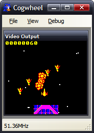
Here's the fictional Super Game Gear, breezing along at 51MHz. The game runs just as smoothly as it would at 3MHz, though - as the game's timing is tied to waiting for the vertical blank.
Actually, I tell a lie - as Fire Track polls the vertical counter, rather than waiting for an interrupt, it is possible for it to poll this counter so fast (at an increased clock rate) that it hasn't changed between checks. That way "simple" effects run extra fast, but the game (that has a lot of logic code) runs at the same rate.
This works. The problem is caused by sound.
With the video output, I have total control of the rasterisation. However, with sound, I have to contend with the PC's real hardware too! I'm using the most excellent FMOD Ex library, and a simple callback arrangement, whereby when it needs more data to output it requests some in a largish chunk.
If I emulate the sound hardware "normally", that is updating registers when the CPU asks them to be updated, by the time the callback is called they'll have changed a number of times and the granularity of sound updates will be abysmal.
A solution might be to have a render loop like this:
for (int i = 0; i < 313; ++i) {
    CPU.FetchExecute(229);
    Hardware.VDP.RasteriseLine();
    Hardware.PSG.RenderSomeSamples(1000);
}
However, this causes its own problems. I'd have to ensure that I was generating exactly the correct number of samples - if I generated too few I'd end up with crackles and pops in the audio as I ran out of data when the callback requested some, or I'd end up truncating data (which would also crackle) if I generated too much.
My solution thus far has been a half-way-house - I buffer all PSG register updates to a Queue, logging the data written and how many CPU cycles had been executed overall when the write was attempted. This way, when the callback is run, I can run through the queued data, using the delay between writes to ensure I get a clean output.
As before, this has a problem if the timing isn't correct - rather than generate pops or crackles, it means that the music would play at an inconsistent rate.
Of course, the "best" solution would be to use some sort of latency-free audio solution - MIDI, for example, or ASIO. If I timed it, as with everything else, to scanlines I'd end up with a 64µs granularity - which is larger than a conventional 44.1kHz sample (23µs), so PWM sound might not work very well.
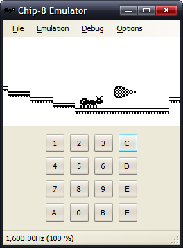
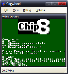
Incidentally, this is not the first emulator I have written - I have written the obligatory Chip-8 emulator, for TI-83 calculator and PC. Being into hardware, but not having the facilities to hand to dabble in hardware as much as I'd like to, an emulator provides a fun middle-ground between hardware and software.

And now for something completely different
Friday, 17th November 2006
A long time ago I thought I'd try my hand at this emulation malarkey.
The hardware is the Z80-based Sega Master System and Game Gear.
Due to the design, it was a huge, messy, poorly written series of hacks that could just about produce the above result if you didn't breathe too hard.
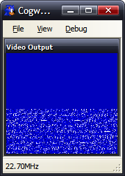
After finding this document, I had a bit of a blast at rearranging the Z80 core and timing the video hardware a bit more correctly. Here's that old Fire Track project:
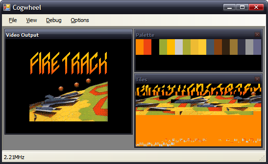
All this does is run the emulation for 100 scanlines on a Timer's tick, hence the low reported clock speed.
The Game Gear's LCD cropped the output screen, so you wouldn't see the junk to the sides of the display here.
My implementation of the VDP doesn't support sprites yet.
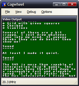
Of course, these are the most exciting screenshots:
Two versions of ZEXALL, one that displays the results on the SMS screen, the other in an SDSC debug console.
One day I shall purge all of these CRC errors. One day! But not now, as I don't have the time to put any work on this (I stole a couple hours for the above), and in spare time (hah!) I should really focus on the Latenite software. Which, whilst it doesn't provide such pretty screenshots, is a great deal more useful.
Subscribe to an RSS feed that only contains items with the Emulation tag.