A larger level, moving sectors and failed optimisation attempts
Monday, 29th November 2010
I've made a few attempts to boost the performance of the 3D engine for the TI-83+ I'm working on with little success. I had previously failed to get any improvement by adding bounding boxes around each BSP node (the idea being that if a node falls outside the view you can discard it and, by extension, all of its children) but the act of transforming the bounding box to determine whether it was inside or outside the view was more CPU intensive than blindly handling the nodes whether they were inside the view or not.
A simpler test, I reckoned, would be to use bounding circles. These only have one point to transform, and determining whether they are in the view is one comparison to ensure that they're in front of the camera followed by one multiplication (by the constant √2) and two more comparisons to determine whether they are to the left or right of the camera's view; far simpler than a bounding box!
The bounding circles did cut down the number of BSP nodes that were handled each frame but the additional checks made the engine slightly slower in general than it had been before. In some circumstances it was slightly faster, but not enough to make a noticeable difference. The additional data per BSP node added over 900 bytes to the level data, too, so the attempted optimisation had to go.


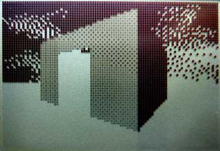
The newly added rooms to the demo level
One tweak that did boost performance noticeably was to cache the projected X coordinate of each vertex. All vertices in the map have at least two walls connected to them and so are projected to the screen at least twice if within the view. I already had a table that was used to indicate whether a vertex had been transformed around the camera or not that frame so it was easy enough to add the X coordinate of the projected vertex to that table, adding around a 15% boost to the framerate.
Points are projected to the screen by dividing their X (left/right) or Z (up/down) component by their Y (depth) component. Division is slower than multiplication so I tried to calculate the reciprocal of the depth for the vertex then perform all subsequent projection operations by multiplying the X or Z component by this reciprocal. Unfortunately, this resulted in a lack of precision owing to my use of 16-bit fixed-point numbers (walls "wobbled" as you moved the camera) and performance was about the same as it had been before, so I rolled back the changes.
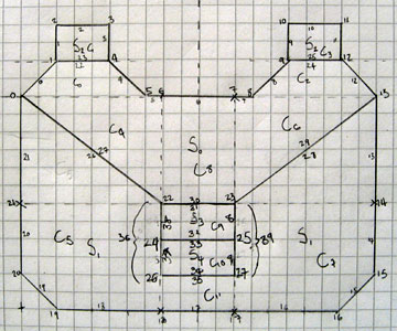
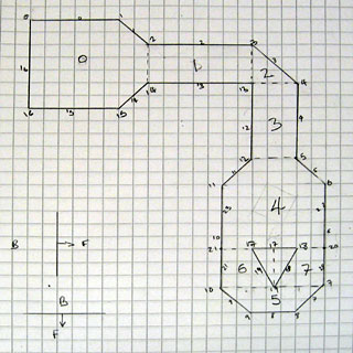
The block of screenshots in the above text shows a new region that has been added to the demo level, and the image below is a map of that level — fans of DOOM may notice that it's based on a small portion of E2M7 (The Spawning Vats).
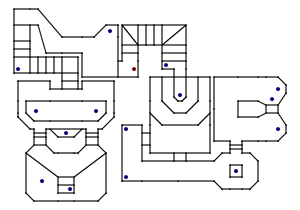
Map of the level
This level now uses every one of the 256 walls that are available, so is probably a good indication of the maximum size of a single level (and at 6,626 bytes it's certainly rather taxing on the limited amount of memory in a TI-83+ calculator).
This is, however, the maximum size of a single level. It does not take long to load and unload levels, so it would be quite possible to construct a continuous level that appears larger by unloading the current one and loading a different one when the user moves to a particular region. This could be implemented in an obvious manner (such as the player stepping into a teleporter) or transparently (by moving the player into an identical copy of the room he left to hide the transition). The latter option also introduces the option of level geometry that would otherwise be impossible in a 2D-based engine, such as rooms above rooms. Special effects could also be tried, such as an infinite corridor that warps you back to the beginning when you reach its end.

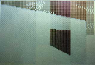
However this feature is implemented, there would need to be some way to trigger the action. The above animated screenshot demonstrates the current trigger system which is used to set a sector in motion. A sector, in this instance, is a region with a particular floor height and ceiling height. Each wall indicates which sector is in front of it and which sector is behind it. Convex sub-sectors contain sets of walls and also indicate which sector they are part of, and are attached to the leaves of the BSP tree. Given a point, you can quickly find out which convex sub-sector it is in by walking the BSP tree. When you have found the convex sub-sector you can then look up its sector. This is currently used to set the player's height, as the sector tells you the floor height.
If you keep track of the player's sector each frame you can tell when they have moved from one sector to another. This then fires an event, reporting which sector the player used to be in and which they are in now. In the above screenshot, the platform is set to descend whenever the sector surrounding it is entered from any sector other than the platform itself (this is to stop it from automatically descending when the player walks off the top of the raised platform). It is also set to rise whenever the platform's own sector is entered. This produces a simple lift; doors are handled in a similar fashion elsewhere in the level.
If you'd like to try this demo on your calculator, you can download the binaries for the TI-83 and TI-83+ in Nostromo.zip. As ever, please back up any important files on your calculator before running the demo; it may well clear your RAM. For those without calculators, an animated screenshot is available.
Collision detection makes the world feel solid
Sunday, 21st November 2010
One of the larger problems with the 3D engine for the TI-83+ calculator series I have been working on is that it's possible to move the camera through walls. This doesn't make the world feel especially solid, so I've started working on some collision detection routines.
Work commitments have left me with little time to spend on this project over the last couple of weeks so progress has been very slow, but I've got a basic collision detection system mostly working.

I spend most of the above screenshot running into walls. The code seems to work relatively well and quite quickly, though it's far from perfect. The still image shows the new settings screen, which is hopefully a little easier to use than remembering which keys do what. It also has the advantage of displaying the state of the current settings.
The walls are stored as line segments between two 2D vertices, and the collision detection has to ensure that the player does not get too close to any of these walls. The technique I have used starts by calculating the closest point on the line to the player.
The above image shows a wall (the solid line segment) and three possible player positions (the heavy dots). The arrows point to the closest point on the wall's line. The closest point on the line to the top player position is past the end of the line segment, so it is ignored. The other two closest points lie on the line segment, so these are checked in more detail.
The distance between the closest point on the line and the player position is then calculated and compared to a threshold value (the radius of the player). The above image highlights the out-of-bounds region in tan. The lower player position is outside this region so is ignored, but the upper player position is inside it and needs to be corrected.
The correction is quite straightforward. We know the closest point on the wall to the player. The angle of the wall's normal is stored in the level file, so we can easily calculate a vector from that to push the player a fixed distance away from the wall.
In addition to the above 2D checks, a very simple height check is performed for "upper and lower"-type walls. These are walls with a central hole so you can pass over or under them, and are used to connect sectors with varying floor and ceiling heights. The top of the player's head is used to check the ceiling height. Rather than use the height of the player's feet to check the floor height their knee height is used. This is to allow the player to climb low walls (such as the edges of steps).
When I first implemented these collision detection techniques I checked every wall in the map. This halved the framerate in places, and as the framerate is not particularly high in the first place I needed to find a way to reduce the number of tests. Taking further inspiration from DOOM I implemented a "blockmap". This breaks the map down into square blocks and each block contains a list of which walls pass through it. To perform collision detection I look up which block the player is in and from that I can retrieve a reduced list of which walls they may end up walking into. The original implementation had to check well over a hundred walls for each movement; the blockmap reduces this to 26 in the worst case scenario for the current level design.
Sadly, this additional blockmap enlarged the size of the map quite a bit, so I've attempted to reduce it a little. For simplicity and performance most structures referred to other structures by pointer (for example a sub sector contained a list of pointers to walls and each wall contained pointers to a front and back sector). I've changed most of these to now refer to other structures by index, which shaved a few hundred bytes off the map at the cost of a few hundred clock cycles. Overall performance still isn't great, though I haven't found it noticeably slower than the previous demos.
I added very primitive physics for moving the player up and down relative to the floor to complement the collision detection. This retrieves the floor height from the sector directly under the centre of the player and compares it to the current player height. If the new floor height is higher than the old floor height then the player's foot height is set to a point half way between the two; this smoothes the animation slightly when climbing up stairs (rather than just snapping to the new floor height). When moving from a higher floor to a lower floor the player's downward speed is increased to roughly simulate gravity.
A demo for the TI-83+ series and TI-83 can be found in Nostromo.zip. As always, this is a piece of software in development and there may be calculator-crashing bugs, so please back up any important files before running it.
Enlarging the world
Sunday, 7th November 2010
There have been very few changes to the features of Nostromo recently. I have tried a number of ways to optimise the performance and whilst the handful of micro-optimisations I have made have boosted the frame rate a little none of the higher-level optimisations have done much. I did try, for example, storing a bounding box around each BSP node and ignoring it (and all its children) should this bounding box fall outside the field of view; the additional code to check the bounding box ended up halving the framerate rather than improving it.


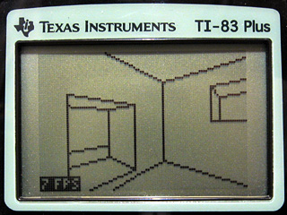
I have, however, enlarged the level quite considerably. A staircase connects the central room with the pit to a rather strangely-shaped arrangement of walls (again copied from E2M7). The room with a pit continues to cause issues; looking across it towards the room with the small central staircase forces the engine to step through a very large number of convex sub-sectors and check many walls. This drops the frame rate down to about 3 FPS on a TI-83+. However, this is specific to that room; the newly-added rooms have not noticeably affected the frame rate in other parts of the level.
Another minor improvement is that the engine now supports different sprites. I'm not too good at drawing them, as you can probably tell from the above screenshots, but at least the code is there to support them.
You can download a TI-83 and TI-83+ binary to try the demo on your calculator (please back up any important files first). Alternatively, here is an animated screenshot.
Adding sprite objects to the 3D world
Tuesday, 2nd November 2010
The previous entry showed a room from a map copied from DOOM's E2M7. I have since added the adjacent room:
It may not look as interesting as the other room but it is significantly more costly to render due to the sheer number of lines visible at a time in it. Looking across it from the far corner dropped performance down to around 2 FPS on the 6MHz TI-83+, which was really not a very good effort. I spent a fair amount of time over the weekend trying to optimise the code as much as I could, and manage to bring the frame rate in the player's starting position from 6 FPS up to the target 10 FPS. Looking across the length of the new room still dropped the framerate to around 4 FPS at 6MHz, but it's a start.
Once the engine had been made a little faster it seemed a good idea to slow it back down again by adding a feature. I had been pondering how to add objects in the form of scaled sprites to the world. Working out where to put them on the screen isn't so difficult, but clipping them against the world geometry so that they couldn't be seen through walls is another matter entirely. One way that seemed popular is to draw the objects in reverse depth order (drawing the sprites that were further away before those that were closer) and using a depth buffer for the world geometry to clip each pixel of the sprite against the world. This would take up a lot of memory on the calculator and run very slowly (populating the buffer with a depth value for each pixel would be a very expensive operation, as you'd have to interpolate depth values between the ends of walls and edges of floors).
The engine makes use of three per-column clipping tables when rendering the scene. One keeps track of columns that have been completed (usually by drawing a "middle" wall to that column); once completed no more pixels may be drawn to that column. The other two tables are used to define the upper and lower clipping bounds. At the start of the scene these are reset to the top and bottom edges of the display. As the world is rendered from front-to-back these regions are reduced to clip geometry that is further away against geometry that is nearer (think of looking through a hole in a wall — things that are further away from you will never be drawn in the space above or below that hole).
Fortunately, you can use this clipping information to clip sprites against the world geometry too. Each sprite object needs to be associated with a convex subsector. These subsectors are made up of walls and are drawn from front-to-back (sorted by the BSP tree) as the world is rendered. Before each one of these subsectors is drawn it is checked to see if it contains any sprite objects — if it does, the current clipping buffers and a reference to the subsector are pushed onto a stack. When all of the walls and floors have been drawn this stack contains a list of all of the subsectors containing sprites and the clipping regions used to draw those subsectors in front-to-back order. Stacks are Last In, First Out structures and so when you pull the data back out of this stack you end up retrieving a list of sprites to draw and the associated clipping regions in back-to-front order. This allows you to effectively unwind the clipping operations, so as you draw the sprites from back-to-front you can gradually enlarge the clipping regions in the opposite order to the way that they were reduced when drawing the walls. You would still need to sort the sprites manually from back-to-front within each subsector, but for the time being I've limited myself to one sprite per subsector for ease of development.
The above screenshots demonstrate an initial test of the "things" (as they are apparently technically called), rendering them as solid black squares.
Scaled sprites tend to be more useful than solid black squares, however, so here are a pair of candlesticks (well, that was the intention at any rate; call them cacti if you must). The sprite was simply ORed to the display, so pixels could be black or transparent.

I then added support for "white" pixels too. The above screenshot is a link to an animated GIF showing the engine in action. The sprites appear to jiggle up and down and have invalid data drawn underneath them in places, which was caused by my accidentally overwriting an important register before rendering each column (fortunately an easy one to spot)! The relatively high frame rate in the above image was helped by running at 15MHz and using the old single-room map.
The above screenshot (click for the animated GIF) fixes the dancing sprites and restores the second room, though is still running at 15MHz. For a bit of fun I added animated doors; all this does is adjust the floor heights of the sectors used to represent "doors" (pressing Alpha will toggle both doors open or shut) but it makes the world look a little more dynamic.
There are still some rendering bugs in the engine. The above animated screenshot demonstrates one; when close to a wall edge you will sometimes see a temporary vertical line the height of the screen or the screen will flash white. I reckon this is probably an integer overflow issue causing the projected height of a line to be on the opposite side of the screen than the one it should be (the bottom edge of a hole in a wall may be projected above the screen rather than below it, causing the entire screen to be clipped out, for example). One bug that took a while to identify (it only appeared in very particular positions; moving one unit in any direction cured it) was caused by truncating a 32-bit integer to a 24-bit one. When viewing a long wall from a long distance the result of a 16-bit (difference between end and start X coordinates) by 16-bit (Y coordinate of the start of the wall) multiplication was resulting in a value of $00800000 or so (a large positive number). When truncated to 24 bits this becomes $800000, which has the most-significant bit set and was therefore treated as a large negative number. As this was part of the wall clipping code it would end up clipping a wall end a long way behind the camera instead of within the view; fortunately this obvious mistake is easy to spot and correct (the answer can only be positive, so if you get a negative one just negate it).
If you'd like to try the demo on your own calculator please download Nostromo.zip. As this is a work in progress there are likely to be bugs so please back up any important files first!
Adapting a room from DOOM's E2M7 to the TI-83+ calculator
Thursday, 28th October 2010
The level I've been working with as a test for the TI-83+ 3D engine was something I quickly threw together. I've never been much good at the design side of things, and my lack of imagination was producing something very simple that wasn't really challenging the engine and testing whether it could be used in a game. Looking for inspiration, I played through map E2M7 in DOOM and found a fairly interesting room to try to convert.
I'm sure you can tell which is the original room from DOOM and which is my adaptation of it.
Since the last post I have had to make quite a few tweaks to the engine. In the previous build there was a bug which cropped up when the top or bottom edges of walls appeared above or below the screen bounds. This turned out to be caused by a routine that was intended to clip a signed 16-bit integer to the range 0-63; it would return 0 for values 128 to 255 instead of 63. Fortunately this was an easy fix.
Another bug was in the way "upper and lower" walls were handled. Sectors have different heights and "upper and lower" walls go between two adjacent sectors and connect the ceiling of one to the other and the floor of one to the other, leaving a gap in the middle.
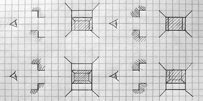
The above picture shows the four main types of sector-to-sector transition through an "upper and lower" wall type. Different transitions require different numbers of horizontal wall edges to be traced; in the bottom left example (going to a sector that has a lower ceiling and higher floor than the current one) four lines would be required and in the top right example (going to a sector that has a higher ceiling and lower floor than the current one) two lines would be required. The previous version of the engine always drew four lines, which would produce a spurious line above or below the "hole" for three out of the four different combinations of sector-to-sector transition. By comparing sector heights the right number of horizontal lines can be drawn, which greatly improves the appearance of the world and slightly increases the performance, too.
A less immediately obvious limitation was in my implementation of the BSP tree structure. Each node on the tree splits the world geometry into two halves; one half is in "front" of the partition and the other is "behind" it. Each chunk of split geometry can be further subdivided by additional partitions until you're left with a collection of walls that surround a convex region. You can then walk the tree, checking which side of each partition you are on to determine the order that the walls should be rendered in. For more detailed information the Wikipedia article on binary space partitioning is a good starting place but the basic requirement is that you should be able to slice up level geometry into convex regions with partitions. I had naïvely assumed that horizontal or vertical partitions would be sufficient (and they are useful as you can very quickly determine which side of a horizontal or vertical line the camera is on). However, this room demonstrated that such a limitation would not be practical.
Consider the above geometry. The black lines are walls and the small grey lines represent the wall normals; that is, the walls face the inside of the "Z". The wall in the middle is double-sided; you could put the camera above or below it and see it. However you slice that map up with horizontal or vertical partitions you will still end up with regions that are not convex.
A single partition along the central wall divides the map into two convex regions. I had initially thought that checking which side of such a partition the camera lay would be an expensive operation, but it's not too bad; as a line can be represented by the expression y=mx+c I can store the gradient m and y-intercept c in the level data and simply plug in the camera's x and compare to y to determine the side. A single multiplication and an addition isn't too much to ask for.
Fortunately, there are only two of these partitions in the level!
I have added some other features to the demo program. Pressing Zoom when using a calculator that can run at 15MHz (a TI-83+ SE or any TI-84+) toggles the speed between 6MHz and 15MHz. Pressing Mode or X,T,Θ,n allows you to look up or down. Pressing Window toggles between the default free movement and a mode which snaps you to a fixed height above the floor. These additions are shown in the below screenshot (click to view the animation):

Unfortunately, performance is lousy. Viewing the stairs drops the framerate to a rather sluggish 6 FPS when running at 6MHz (most of the above screenshot is recorded at 15MHz). The LCD's natural motion blur helps a little (it feels a lot more fluid on the calculator than it does on a PC emulator) but I'm aiming for a minimum of 10 FPS, so I need to make quite a few optimisations. There are several low-level ones that could be made; for example, when clipping the 2D line segments to the display I'm using a generic line clipper that clips the line both horizontally and vertically. As wall has been clipped to the horizontal field of view by that point I only really need to clip it to the top and bottom edges of the display. There are also some high-level optimisations to be made; for example, double-sided walls are currently stored as two distinct walls with the vertex order swapped. This means that to handle both sides of the wall the engine has to clip and project it twice, which involves lots of expensive divisions and multiplications. The results of these operations could be cached so that they only needed to be calculated once.
A TI-83 and TI-83+ binary is available if you'd like to try the demonstration on your calculator: please download Nostromo.zip. The usual disclaimers about backing up your data before running the program apply!
Varying wall heights in a 3D engine for the TI-83+
Monday, 25th October 2010
I've done a little more work on the 3D engine for TI-83+ calculators that I mentioned in the previous entry. The main difference is in limited support for varying the heights of floors and ceilings, illustrated in the following screenshots.
Walls now refer to one or two "sectors". A sector is a 2D region of the map of any size or shape; it can be concave or even have holes in it. Walls are also grouped into convex regions named subsectors for rendering purposes. Each wall has a sector in front of it and a sector behind it; these sectors have a specified floor and ceiling height. There are now two types of wall; a "middle" wall which connects the floor and ceiling of the sector in front of it and an "upper and lower" wall which connects the ceilings of the sectors on each side and the floors of the sectors on each side.
This makes occlusion a little trickier and determining where to draw lines around the edges of walls even more so!


The previous version of the renderer worked by drawing walls back-to-front, clearing rectangles the height of the screen behind the wall segments as they were drawn. The first attempt to improve this exchanged rectangles the full height of the screen with trapezia. The screenshot to the left shows the bounding rectangle around each wall segment being filled and the one to the right shows each wall filled as a trapezium. (As before, clicking an image with a border will display an animated screenshot).
Rather than attempt to calculate where lines should be drawn around wall edges I thought I'd experiment with dithered wall fills instead. The left screenshot shows this addition (each wall has a different shade) and the right screenshot shows the addition of support for wall heights (still drawn in the simple back-to-front technique, resulting in significant amounts of overdraw).
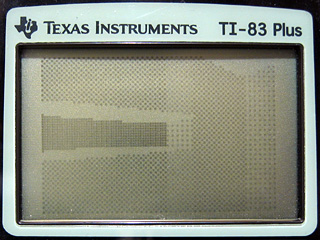
Unfortunately, the LCD on the calculator copes rather poorly with dithered fills; the above photograph was taken at the highest contrast setting. Rotating the camera to look at walls with a different dither pattern brings the world back into view. This is rather unacceptable, and is something I ran into with my previous implementation. I think I'll stick to stroked wall outlines rather than filled walls.
I had been experimenting with a new level design in the C# prototype of the engine that added another room accessible via a tunnel from the starting room. I added some code to the C# program to output the level data in a form that could be assembled into the Z80 version. This is shown above, having reverted to a simple wireframe view in anticipation of the new wall drawing code.
The new way to implement occlusion works very differently to the previous one. I had been sorting the geometry from back-to-front and rendering it in order, drawing walls in the foreground on top of walls in the background. This wasn't very efficient and wouldn't scale well. The new approach renders from the front to the back and works on information stored about each column of pixels on the screen. The screen is 96 pixels wide, so there are 96 columns to deal with. A counter is set to 96 at the start of rendering. When a column of a wall is rendered, a flag is set to indicate that that column has been completed and the counter is decremented. When the counter reaches zero, that means that every column on the screen has been completed and the renderer terminates. This is demonstrated in the above screenshot when compared to the previous one; walls that are some distance away from the camera (and behind other wall segments) are not always drawn as the renderer has decided that it has finished before reaching them.
An obvious issue with the above screenshot is that even though some of the geometry is culled, individual walls can still be seen through other ones.
Part of the solution is to use a custom line-drawing routine that checks each pixel against the completed columns table. If a column is marked as completed, the pixel is not drawn; if it isn't, the pixel is drawn. This is shown above.
I previously mentioned that there were two types of wall; "middle" walls (solid ones from the floor to the ceiling) and "upper and lower" ones (these have a hole in the middle). Only "middle" walls flag a column as being completed, as you need to be able to see through the hole in "upper and lower" ones. This causes the rendering bugs in the previous screenshot above and below the holes in the wall. The way to fix this is to add two new per-column clipping tables; one which defines the top edge of the screen and another which defines the bottom edge. These both start at the maximum values (0 for the top edge and 63 for the bottom) and are reduced whenever an "upper and lower" wall type is encountered.

The new code to do this is demonstrated in the above screenshot. There is still, however, a bug in this implementation. The per-column clipping tables are updated by the code that draws the line along the bottom or top edge of the hole in the wall. If this line is partially (or completely) off the screen, these tables are not updated and the rendering bugs appear again (as demonstrated at the end of the above screenshot). A final manual pass over parts of the line that are clipped off the screen corrects the issue:

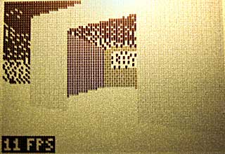
As can be seen in the bottom left corner of the above screenshot I have added an FPS counter. This is accompanied by code that scales movement by elapsed time so you move at the same speed regardless of how long each frame takes to render. The engine is quite slow (and could no doubt be heavily optimised by someone who's good at assembly) and has quite a few bugs in it but it's certainly looking a little better than it did a week ago. As I only have a regular TI-83+ I'm aiming for something usable at 6MHz; the more modern calculators can run at 15MHz but this feature is not used in the demo.
For those interested in trying the demo on their calculators, click on the above image to download an archive containing a TI-83+ and TI-83 binary. As before, this is experimental and may well crash your calculator, so please back up any important files first!
A primitive 3D engine for the TI-83+
Sunday, 17th October 2010
As you may have guessed from the number of spinning cubes in my projects, I am quite fond of primitive 3D. As you may also have guessed from the number of TI-83+ calculator projects I have undertaken, I'm also quite fond of programming on low-end machines. I have never really successfully put 3D and the TI-83+ together, though.

One way to build a 3D world in software is raycasting (e.g. Wolfenstein 3D). This typically results in blocky worlds where all walls are at 90° angles to each other. There are several games using raycasting engines on the TI-83+ already; they are much faster and better-looking than my sorry attempt pictured above.

Another method is to use true 3D geometry (e.g. Quake). Many years ago I attempted to work on something that looked a little like Quake. I built this on the Matt3D engine, which supported basic 8-bit coordinates and lines, but not solid objects. The result was even less useful than the above raycaster!

Another method somewhere between the two is a "2.5D" engine, where level geometry is defined between points in 2D space but projected in 3D (e.g. DOOM). This allows for walls that are not at 90° angles to each other, whilst simplifying the rendering procedure significantly. I spent some weeks working on such an engine a few years ago yet never managed to get any further than the above screenshot. As you can probably tell from the fact that you can see the walls through each other I never found a good way to handle occlusion, and the project ended up stagnating.
Looking for a quick weekend project I thought back to the work I'd done with the DOOM and Quake engines. These engines use a BSP tree structure to sort the level geometry for rendering. I reckoned that if simplified a little a similar tree structure could be used to render a 3D world on the TI-83+ calculator. The four screenshots above show that this technique is indeed quite successful. My implementation could certainly do with a lot of work but I think the theory is at least sound.
I decided that one way to make this project a bit more fun was to set myself a challenge; to design a level that I would, ultimately, be able to walk around in. This level is shown above, and contains a number of walls that are not parallel to the X or Y axis and a pillar. I have split the world into eight convex "sectors" (labelled 0 to 7) with a dotted line between them to show where the BSP tree is partitioned. All of the partitions are either horizontal or vertical to speed up tree traversal; the TI-83+'s Z80 CPU does not support floating point arithmetic, let alone multiplication or division, so being able to decide which side of a partition you're on quickly is very useful.
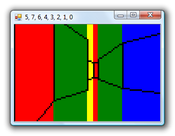
Rather than dive straight into Z80 assembly programming I knocked together a quick prototype in C#. This allows for quick and easy debugging; the blocks of colour allow me to quickly identify walls and the application title bar contains the order in which the sectors have been rendered. These can then be checked against the version running on the TI-83+ in case there are problems.

With the C# version running satisfactorily I started converting it to Z80 assembly. The above screenshot shows the first step; transforming the level's vertices around the camera. Clicking on the screenshots will take you to an animated version; as some of them are quite large I have linked to them rather than embedding them directly.

The next step was to traverse the BSP tree. The numbers across the top of the screen indicate the order in which to render the sectors, from back to front — however, due to a simple bug, they are actually listed from front to back. This was fortunately very easy to fix.

Walls are connected between the vertices, so I quickly threw something together to display all of the walls on the screen. The walls will have to be clipped against the camera's view (or discarded entirely if they are outside the view) so being able to see them is a great debugging aid!

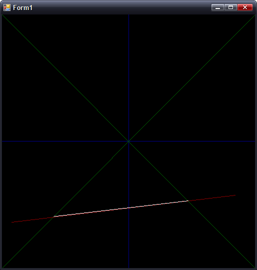
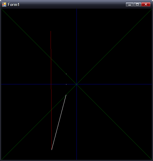
We are only interested in drawing walls that are in front of the camera, so the first bit of clipping code deals with clipping the walls against Y=0.


The above screenshots show the final three stages of clipping to the camera's view, defined by Y>0, Y>+X and Y>-X. The first screenshot shows culling of any wall that does not satisfy this in any way; walls that are completely outside the view are discarded. The second screenshot shows walls being clipped against Y=+X, and the third finally adds clipping against Y=-X. The lack of hardware floating-point arithmetic makes the code fairly slow and ugly but it does seem to be working relatively well.
We are only really interested in dealing with walls that are facing the camera; we don't want to draw the back of walls. To work out which we want to keep and which we want to ignore, we project the wall to the screen and check whether its projected start vertex appears to the left or the right of its end vertex.


A simple perspective projection is performed to turn this clipped 2D world into what appears to be a 3D one. The X coordinate of each vertex is divided by its Y to get the X coordinate on-screen and the height of the wall is divided by the vertex Y to get the Y coordinate on-screen. The left screenshot shows the top and bottom of wall edges; the right screenshot adds lines between the floor and the ceiling to produce a more convincing "wireframe" view of the world.

The final step is to make the world appear solid, by hiding walls that are far away behind walls that are closer to us. Traversing the BSP tree gives us the order in which to draw the walls, so all that is required is to draw solid quadrilaterals for each wall rather than the lines around its outside. A fast clipped quadrilateral filler would take me some time to write so I cheated by drawing a solid white rectangle the width of the wall and the height of the entire screen before drawing the wall outlines. As the camera is half-way up each wall and all of the walls are the same height there are no cases where a foreground wall only partially covers a background one so this trick works for the time being.
I'm glad I achieved my goal of walking around the 3D world I'd sketched in pencil at the start of the weekend but I'm not sure where I'll be able to take the project now. Turning it into a useful 3D engine for a game would certainly require a lot of work. The level and its BSP tree were generated by hand, which would not lend itself well to anything but the simplest of levels. However, the lack of variation in wall heights produces fairly dull levels in any case; DOOM-style levels would be something to strive for, but I'm not sure how well the calculator would be able to cope with them. I'm also unsure how well the engine would scale; this very primitive version only achieves around 12 FPS on a 6MHz TI-83+. It's certainly given me something interesting to think about!
If you would like to try the program on your calculator, please download Nostromo.8xp. It requires an Ion-compatible shell to run. It is very primitive, likely to be quite buggy (you may encounter rendering bugs when very close to walls due to integer overflow in the clipping and projection code) and may well crash your calculator; please back up any important files before running it. Use the arrow keys to move around, Trace and Graph to strafe and Clear to quit.
Map Editing
Wednesday, 26th July 2006
I added five-level grey:
The greyscale effect is optional (adds about 8 lines of code, only runs once per frame and can be disabled with a single switch in the engine package's Settings.inc file.
Anyway, I've started throwing together a very primitive level editor. (GDI+)
Insert inserts a new vertex at the mouse location; delete removes the closest vertex. Point at a vertex, hold W, move to another vertex and release W to insert a new wall. (Single-sided, hold shift at the same time to add a double-sided wall). Use D to remove walls in the same way. That sort of thing.
The two different types of wall are represented with white lines (single-sided) and grey lines (double-sided). There are therefore 9 different sectors in the above image.
Imagine that the walls have been kept simple (fixed floor/ceiling heights, single segment) and can have one of 6 different 'colours' - from 0 (invisible/transparent) to 1 (white) through to 3 (50% grey) and finally 5 (black).
Therefore, for the sake of simplicity, assume that all of the double-sided grey walls in the above screenshot are invisible. The room in the south-west of the screenshot is an octogonal room with a doorway in the eastern wall and a square pillar in the middle.
The four double-sided walls in this south-western room are not redundant. You will notice that the level has been cut up into convex sectors. This has one small advantage - it reduces the number of walls that will need to be sorted, as I only need to sort entire sectors for occlusion purposes.
Also, I can see that I can get some sort of portal*-based system up and running. Suppose I use the editor to create this:
If I was to start in the left sector, I would go through and draw each wall. I'd hit the double-sided wall at some point, and know that after this sector I'd have to move into the sector in the middle. After that sector, I'd know that I'd have to move to the sector to the right. With me so far?
Let's do something radical and make that central sector a door, and close it (move the ceiling height down to meet the floor height). This time, when I move through the sectors, I'll hit this sector and see that it's closed. No matter, say I - rather than carry on walking through the sectors, I stop at that point.
By liberally sprinkling a world with doors, and keeping them shut most of the time, you can cut out a fair chunk of geometry. :)
I cannot think of the best way to handle sorting. I don't think I can just use the order in which I wander through the sectors - imagine this:
Imagine you're in the north 'triangle' and looking south. As you can see, you need to travel through more sectors to get to the larger rectangular room than the south triangular room - and using that for sorting is just wrong.
One potential workaround I can think of is that each sector has a visibility list - a list of in which order sectors appear (in front->back order - else we wouldn't be able to take advantage of portals). Problems; MASSIVE amount of data that grows exponentially with each added sector! From what I can also tell, that also seems a precomputed BSP list, done per sector (rather than work out which side of the split to follow each branch, it's already calculated for us). On the other side, this can also be used to calculate (through some nifty ray/plane intersection algorithm) which sectors will NEVER be visible from a particular sector... Hmm. I'm not afraid of 'wasting' RAM with gigantic tables - if we assume a smallish, plain level of 50 sectors, each sector would need a list of at most 49 other sectors. 49*50*2=4900B - not actually too bad. :
(Bah) Just realised that would not work (precomputed sorting based on sectors) at all.
Let's say the red line is your 'view' (not a wall, quick and dirty diagram). It intersects the front of two walls, so it appears that the sort should go north->east->west sectors. However, imagine I move to the other side of the sector and look the same way (mirror the diagram, basically). Now the order goes north->west->east, and I'm still in the same sector :( Do I just clump all the sectors together and sort them all together based on the distance to the central (average) coordinate of each and the camera? (Not fast!)
Thoughts?
*I hope that's the correct word.
Coloured walls and FPS counters
Monday, 17th July 2006
I fixed most of the wall filling code. It now fills by scanline (so is considerably faster), which gives me more flexibility over what I can do with it.
For the moment, I have sacrificed speed with a routine that can handle three different fills - black, white, or 50% dithered. The routine will always blank the wall, mask out the pattern you wish to fill then OR it - which works nicely, but wastes time if you are filling plain black or white walls.
The result is quite pleasing:

As you can also see, I added scrolling skies.
The dithered walls look a bit nicer on hardware. The option to switch the initial dither pattern on alternate frames (resulting in a pseudo-greyscale) can be switched on or off, as it looks rather bad in emulators.
There is one horrible problem with the physical LCD, though - it really cannot cope with columns of alternating pixels. Compare the two shots, one being much closer to the wall (and so having more columns of alternating pixels):
Not so good. Hopefully the world in-game will have enough content to break up the columns, but I'll have to wait and see on that count.
One major concern I've had is keeping the speed of the engine constant. Just moving the player X units per frame is not an option, as the framerate can vary wildly. I need some sort of timing!
Luckily, the calculator has fairly limited timing hardware built-in. I can use this timer via interrupts. There are various pieces of hardware that can trigger interrupts - including the On key, activity on the link IO port (any line held low will trigger an interrupt) or this timer. The TIOS seems to use this timer to scan the keypad a few times a second, so it can read a key and store it for the key reading routines.
Fortunately, it is possible to take advantage of interrupt mode 2 on these calculators to install your own handler. When the engine is initialised, it adds the new handler - which is very simple. All it does is increment a 16-bit counter!
I added a piece of code that read this value and set it to zero each frame, displaying the result (ticks). I then added a piece of code that toggled the data lines of the link IO port, and used a PC program to monitor this rate (I used this technique before to work out interrupt-based timing for the 60Hz CHIP-8 clock). By comparing two extremes - a large viewpoint where I could see all of the walls, close up and a viewpoint where I could see nothing, I could see that one view ran at 16FPS and accounted for 20 ticks, and another ran at 44FPS and accounted for 8 ticks. This shows that one tick is approximately 3ms long, and that a FPS counter could be implemented by dividing 333 by the tick count.
A quick check with my PC program shows that the counter is fairly accurate (close enough for my liking). I can now use these tick counts to scale the movement of the player, so the speed is consistent. Another advantage is that I can set the SE edition calculators to 15MHz, and they can benefit from more fluid framerates (nb: any program I run will still need to run merrily on the 6MHz calcs for me to be happy. I'm not going SE-only!)
That's not to say I can now go and build an exciting level and release a nifty demo. There are still big holes in the engine - simple graphics bugs, like the wall filling code still not supporting top edge slopes with a y difference of over 127: (overflow-related bug)

...to there still not being any proper occlusion (sorting)...
I'd like to get occlusion up and running, so I can throw a nifty level together (for example, showing off non-90° walls). Thing is, it's tricky trying to show off cool stuff and not walk into an area where you can see the world isn't quite as solid as it should be. 
Filling
Friday, 7th July 2006

I chucked some simple filling in to the engine as a test. It scans along the top and bottom edges of the shape, then fills columns. This is rather inefficient (filling scanlines is much faster - the screen is shorter than it is wide, so tracing Ys for the boundaries is faster than scanning Xs, and when filling by scanline you can write 8 pixels - a byte - in a single shot) but it served the purpose of a quick demo. It's rather broken, and doesn't match the lines correctly (so there are slight gaps and overflows). It's only temporary.
I'd like to extend the filling to support different dithered fills - white, 25%, 50%, 75% and black walls would look nice.
There is no sorting as yet, I just arranged the walls in back-to-front order in the level file.
@philipptr: I don't know if you ever completed your triangle filling, but the way I've done it in the past is to split the triangle into two halves (y0→y1 and y1→y2, where y0<y1<y2). I would then trace down the sides of the triangle, calcuating the X bounds for the top and bottom halves (Bresenham), then filling in the horizontal lines using these values. Only uses integer arithmetic, so nice and fast.
Whether this will be turned into a game or not depends on whether I can get it to scale sensibly with decent-sized levels; especially with the addition of scaled sprites. If I can get a nice sized level that you can walk around nicely, then I'll try and add a game - pointless planning a game around an engine that isn't up to par!
Clipping works! (Almost)
Monday, 3rd July 2006
Clipping now works in nearly all cases:

One of the problems was lack of precision. Here's the typical case that worked, running in my mockup:
In this case, where |dX| > |dY|, all is good. However, switch that around so that |dY| > |dX|, and you get the following:
(Fixed point isn't so good for holding values that tend towards infinity). The solution is to have two branches for the clipping arithmetic, switching to the alternative form when |dY| > |dX|.
Preparation:
m = (Y1 - Y0) ÷ (X0 - X1) ; m is negative gradient.
c = Y0 + m × X0 ; Not sure what to call this, but it's used in all the below calculations
Clipping to y = 0:
x = c ÷ m
y = 0
Clipping to y = +x:
y = c ÷ (1 + m)
x = +y ; not used as we can skip having to transform.
Clipping to y = -x:
y = c ÷ (1 - m)
x = -y ; not used as we can skip having to transform.
The reason for clipping to y = 0 is to make sure the line is clipped to the correct side.
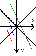
If you look at the red and blue lines, you can see that the far out-of-range points both have x < 0. This indicates that you should clip to y = -x. However, the green line also has the far end at x < 0, but we actually need to clip to y = +x. We can fix this problem by first clipping to y = 0, then checking the sign of x.
To fix the steep gradient problem, I just need to switch to these alternative sums:
First up, the gradient and c are calculated as:
m = (X0 - X1) ÷ (Y1 - Y0) ; Flipped
c = X0 + m × Y0 ; Again, X/Y flipped.
For clipping to y = 0:
x = c ; No need to divide by m!
The only other difference is to make sure that when clipping y = -x:
y = c ÷ (m - 1) ; as opposed to (1 - m)
...and all is hunky-dory.
The only remaining problem is if you are positioned directly inside a wall, which collision detection should fix.
Clipping
Tuesday, 27th June 2006
Clipping (adjusting walls to ensure that they are in the field of view so that they can be drawn correctly is being a right pain).
Firstly, I rewrote some of the really ugly wall-handling code:

Clipping follows the fairly simple maths:
(Where m is the gradient of the wall). The resulting Clip value then corresponds to the new (X,Y) coordinate - if you want to clip to x=-y all that's needed is (1 - m) becomes (1 + m) and Clip must be negated before using it as the new X coordinate.

The result (with added adjustment layer to turn the grey clipped line into red for clarity's sake) seems to work pretty well.

...or not. When implemented with the rest of the code, something goes rather wrong when I look at the wall from the wrong side. Thankfully, that was a simple bug in the division routine, causing it to trash the accumulator when one of the operands was negative (the accumulator itself formed part of one of the operands).

With that fixed, things look a bit more positive, but it's still rather unstable.
Latenite 1.0.6.0
Tuesday, 20th June 2006
There's a new Latenite beta - 1.0.6.0 - available from my site. I hope this is the last Latenite 1 release; I'm moving away from the current IDE towards a revised Latenite 2, the focus more on interactivity with the assembler and the debugger (better 'Intellisense', breakpoints, variable watching and so on). This mainly revolves around a much improved text editor, currently in the works.
Not a very exciting thing to look at, but handling text selection, editing, copying, pasting, and highlighting - and keeping it fast - is being a bit of a pain.
For the most part, it is fast enough, but gets seriously sluggish when scrolling up and down at high resolutions (has to repaint the entire control as none of it is buffered).
That little 3D engine for the calculator I was working for (codenamed Nostromo) is not dead, as you might have thought;

(Old screenshot to refresh your collective memories). I have recently 'ported' the TASM-style code to the new Brass syntax, rewritten all of the wall handling code for increased performance and fixed some of the graphical glitches caused by overflow (lines wrapping incorrectly around the display). I have increased the resolution and accuracy of the maths in use as well, but it's still pretty sluggish with large amounts of data and still lacks occlusion and wall clipping to the view.
One (easy) way of speeding things up would be to split the world up into 'rooms' (or zones, pick whatever terminology you like) where each room is entirely self-contained and cannot be seen from any other room. By opening and closing doors between rooms you can add and remove which rooms are in the list to be drawn, keeping the geometry count low.
Of course, for this to work, I'd need a bit of collision detection to be able to work out which room the camera is in.
In terms of occlusion, I'm a bit stumped. As far as I can tell, BSP might be the way to go, but have never been able to write a working 'BSP engine'. If anyone had any links they'd recommend on the theory and implementation behind this, I'd be very grateful.
Variable height sectors
Wednesday, 12th April 2006
I switched from 16/8 division to 24/16 division, and wall heights are now calculated rather than being dragged off a lookup table.
There's also backface culling (the cylinder around the central cube is marked as double-sided, hence no culling there) but there is still no clipping or occlusion.
@philipptr: I'm guessing your technique is to calculate the angle of the point, add an offset to it, then convert back into a new coordinate? I just adapted some 3D point rotation code I had, simplifying (mathematically) it and removing any references to z.
I will probably not use textured walls - not so much for performance issues, but for aesthetic reasons. Scaling a texture down on a wall displayed on a 96x64 monochrome display (without antialiasing) looks pretty ugly. Simple lines look a lot cleaner.
Oh, and hello aCiD2 
Oldschool 3D
Wednesday, 5th April 2006
All this DOOM work had got me interested again in simple 3D engines, and so thoughts turned to my favourite Z80 platform, the TI-83 Plus.
There are a handful of 3D engines out there for it already; Matt3D is a vector-based wireframe engine put to good use in a roller-coaster builder/simulation game and a racing game (that even supports two-player over the link port). However, it's 8-bit and so worlds created with it tend to be very small or distorted thanks to low-resolution (I tried writing a Quake game with it years ago).
The best "wall" engines (displaying a 3D world rather than a 3D object) have been the raycasters. Gemini impresses me the most; it's a Wolfenstein-level engine with objects, sliding "half-block" doors and moving wall blocks, all neatly texture-mapped.
I'm going to try, therefore, to get a vector-based "wall" engine (there must be a proper term for it) up and running. Keeping the map to 2D simplifies the maths a lot; hopefully with a few tricks things should be fast enough! Also, I'll use 16-bit arithmetic throughout to enhance the quality and scale of the maps.

Like DOOM, I'm isolating the vertices from the wall definitions. This way, I can cut down on the number of rotations/transformations required. The maths required to rotate a point around the origin is fairly simple;
Yr = Xo × cos(a) - Yo × sin(a)
For the moment, I'll use a simple lookup-table for wall heights. Ultimately, I'd like to have variable height walls, but these will do for the moment:

The translated X is just 48+(Xr/Yr), as the screen is 96 pixels wide.
Throwing in a few extra lines for walls...

As you might be able to see, there is no clipping if any part of a wall falls outside the viewing range. Also, the walls are not occluding eachother, something you'd really want.
Subscribe to an RSS feed that only contains items with the Nostromo tag.