Integrating the dsPIC33 VDC with the Z80 computer
Saturday, 31st July 2010
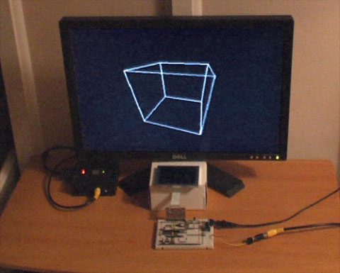
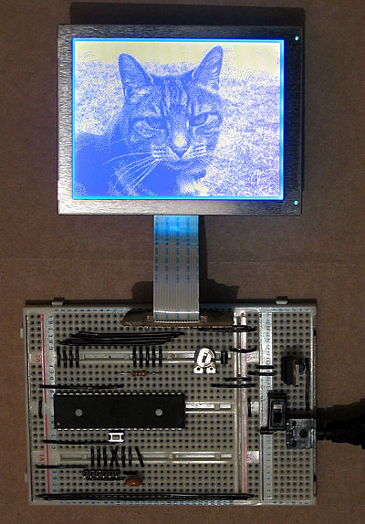
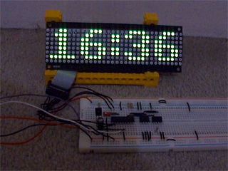
The ultimate goal for the video display controller module I have been working on is to drive the display in my Z80 computer project. As I have now got a pretty good set of features I thought it would be a good idea to join the two projects together.
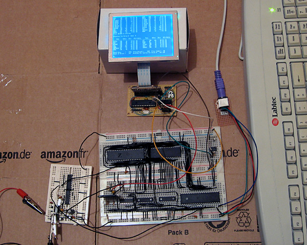
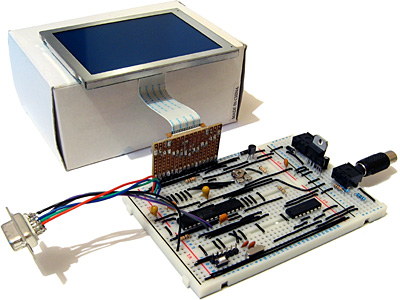
The big board in the lower middle of the above photograph is the main body of the computer, including the Z80, its RAM, the ATmega644P that is used to handle I/O, an SD card for storage and a DS1307 real-time clock. The small board in the bottom left of the photo is the power supply (supplying both 5V and 3.3V) and clock generator (providing a 20MHz and 10MHz clock).
At the top of the photo is the video display controller, connected to a 320×240 graphical LCD. A pin header is used to connect this VDC board to the rest of the computer. Three pins are required for power; 0V, 3.3V (dsPIC33 and output buffer) and 5V (LCD). The VDC is connected to the computer's ATmega644P I/O controller using the two-wire I2C bus (the same bus that is used to access the DS1307 clock). Rather than run a series of graphical demos, the VDC now waits for commands to be written to the I2C slave address 0xEE which it acts on to control what is shown on the screen. I'm aiming for these commands to work in the roughly same way as they did on the BBC Micro VDU, which should make porting the enhanced TI-83+ version of BBC BASIC to this computer a bit easier. The BBC Micro's VDU could be accessed by calling OSWRCH (assuming it was being used as the current output stream), which typically has an address of &FFEE — hence my choice of 0xEE as the I2C slave address!
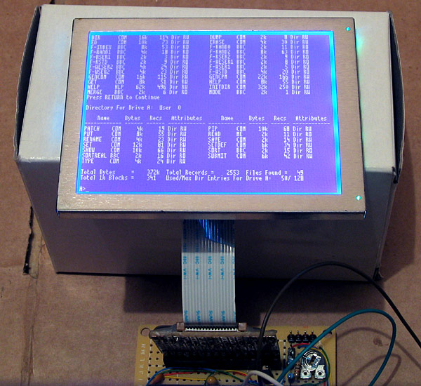
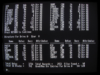
A handful of these VDU commands have been implemented, which is sufficient to run simple CP/M software. The generic CP/M version of BBC BASIC does not, naturally, support any hardware-specific features and as such lacks advanced text or drawing support (one can send commands directly to the output stream with the VDU statement but this isn't very user-friendly). I will need to work on this now that the hardware is coming together! The current VDC code can be downloaded here if you are interested in the changes that have been made.
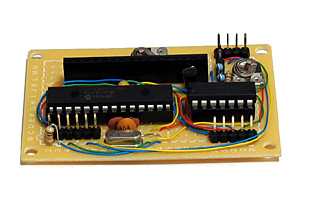
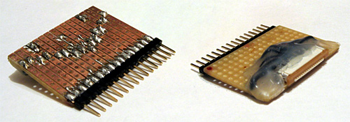
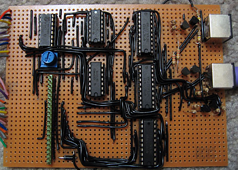
The above photo shows the newly constructed VDC hardware. All of my previous projects have been assembled on stripboard; as the projects have become more complex or simply smaller I've found stripboard to be increasingly awkward to work with. ICs can only really be orientated in one direction, and to reduce the size of circuits I've had to start cutting the tracks between holes (rather than the usual method which is to drill out an entire hole). The supplier I normally acquire parts from, Bitsbox, recently added three different sizes of perfboard to their catalogue so I thought I'd give it a go. I've found it much more pleasant to work with than stripboard, though not as easy to correct if you make a mistake and need to desolder a connection. You can certainly perform some interesting space-saving tricks on the underside of the board!
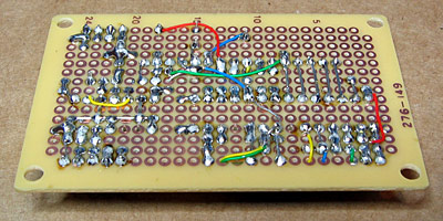
The Kynar insulation on the wire I switched to using also has the advantage of not melting when heated with a soldering iron, as I've had problems in previous projects where tightly-spaced wires will end up getting shorted together as the insulation between them melts.
I have mentioned that one pin header is used to connect the VDC to the computer. There are three others on the board; the two-pin one is for the composite video output, the six-pin one is for connection to a PICkit to reprogram the dsPIC and the four-pin one for the VGA output.
Now that I have moved the VDC onto a permanent circuit board I feel that I can start moving the rest of the computer in the same direction. The software is far from complete and the hardware is pretty rudimentary but it does basically work and having a more robust system to work on should make life a bit easier.
VGA output for the dsPIC33 VDC
Sunday, 25th July 2010
I have spent quite a while working on different projects that generate PAL video signals in software. This may seem a bit odd if you consider the fact that I don't own a TV, so tend to rely on a video capture card or VGA box to see the output of these projects on a computer monitor — something I do have a fair number of.
This reliance on another piece of technology between my project and the display device is not something I'm too keen on, so have spent some time adding native 640×480 60Hz VGA output to my dsPIC33 video display controller.
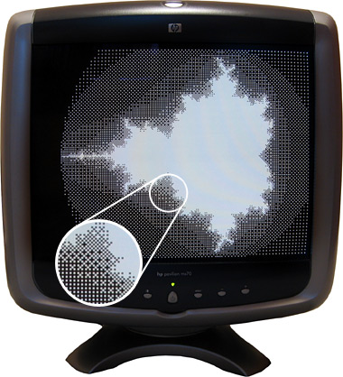
Another advantage of using a VGA monitor directly is that individual pixels are shown very crisply, unlike my video capture card or VGA box which tend to blur the image horizontally. This is shown in the zoomed in part of the above photo.
Generating a video signal for a VGA monitor is easier than generating a composite video signal for a PAL TV, as there are distinct pins for the image data, horizontal sync and vertical sync. One problem I did have, however, is with the length of the vertical sync pulse. I started with a very brief pulse (the same duration as the horizontal sync pulse) which worked fine with my old analogue CRT monitors but didn't work at all with my modern LCD monitor. The documentation I was using for timing information indicated that there were "two scanlines" for vertical sync so I extended the pulse to last for those two frames, which worked on the LCD but didn't on the CRTs. My final compromise has been to assert the vertical sync pin for the duration of a single scanline, which seems to work on all of my monitors.
When connected to a TV two microcontroller pins are used to drive a single load (composite input). When connected to a VGA monitor, however, a single microcontroller pin is used to drive three loads (red, green and blue inputs). I thought it prudent to check the datasheet for the dsPIC before connecting this increased load to the output pin where I was surprised to discover that the maximum source or sink current for each output pin is a measly 4mA — not even enough to drive an LED! I have added a buffer to each video output pin to protect the dsPIC — any buffer capable of sourcing up to 30mA or so should be sufficient (I'm using a 74F125, which can be seen in the bottom right of the above photo). I had previously been occasionally using the video output pins as inputs to check if there is a load on the output or not (such a load would indicate whether a TV or VGA monitor is plugged in or not) but I can no longer do this with the external buffer IC so have had to revise the circuit somewhat. Updated source code featuring the new VGA output code and an accompanying schematic are available for those who are interested!
Text and filled shapes for the dsPIC33 VDC
Thursday, 22nd July 2010
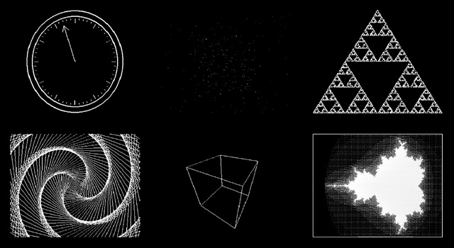
The dsPIC33 video display controller project I am working on needs to support several common text output and drawing operations offered by existing BBC BASIC implementations. The previous demo included basic point, line and circle outlining functions, but I also need to output text and outline (or fill) rectangles, circles, ellipses and triangles. On top of that the drawing operations need to support multiple colours and plotting modes. Owing to processing power and memory limitations the output is black and white only but different "shades" can be implemented with dither patterns. The plotting modes allow you to perform logical operations between what you are drawing and what's currently on the buffer — for example, you could fill a circle that is logically ORed with the existing background or draw a line that inverts every pixel along its length rather than applying the new colour.
Filled rectangles and text output produce the above image.
Finding suitable algorithms for some of these routines has been a little tricky at times. Due to the way that filled shapes can be set to invert (rather than overwrite) what's on the background there has to be zero overdraw and the outline of filled triangles should exactly match the outline of a triangle drawn by plotting a line between its three vertices; this makes combining triangles to form more complex shapes possible, as you can guarantee that the overlap between the two shared vertices of a pair of triangles covers the same pixels as a line drawn between those two vertices.

Filled triangles produce a solid cube.
I ended up writing a program in C# that would plot a random triangle using the triangle filler I was attempting to write and then compare its outline to that of a triangle drawn by plotting lines between the three vertices. The final code is chock full of special cases and workarounds but has been tested against hundreds of thousands of random triangles and seems to be working!
Due to a shortage of memory there is only a single frame buffer, which (naturally) means there is no double-buffering and hence smooth animation becomes a little tricky. When connected to a TV one can take advantage of the vertical blanking period to update the buffer (this is a period below and above the active display where you only need to feed sync signals, not image data, to the TV) and still get decent effects as long as you don't try to do too much. The LCD has no such vertical blanking period and so some of the demos look rather flickery.

I have captured a video of the output of the circuit when running the demo which can be seen above. The horizontal grey lines are a limitation of my video capture card; these lines appear correctly as alternating black and white pixels on a real TV set! You can download the code for this demo from my site along with a PDF of the schematic. As this is a work in progress I'm sure there are plenty of bugs left to squash but I think it's getting there, slowly but surely!
dsPIC33 VDC with GLCD or PAL TV output
Sunday, 4th July 2010
I have currently been using some terminal emulation software on my PC to see the output of the Z80 computer. It seems a little silly to rely on a large multi-gigahertz, multi-megabyte machine just to display the output from a machine at the megahertz and kilobyte end of the scale. I had previously done some work with a dsPIC33 to drive a 320×240 pixel graphical LCD so dug out its breadboard and dusted off the code to try to make something of it.
Inspired by John Burton's recent experiments with PAL TV output I decided that the first thing I should do is add support for TV output. The graphical LCD is nice but a little small and responds to pixel changes rather slowly, making animation very blurry.
I think the results are reasonably good. A lot of the code is shared with the old LCD driving code, which means that the LCD demos work fine with the TV too. Fortunately, retracing the TV is a much less CPU-intensive job than retracing the LCD. The PIC has an SPI peripheral that allows you to clock out eight or sixteen bits a bit at a time at a selected speed by writing to a single register, which is great for clocking out the pixel data on each scanline. Even better are the PIC's DMA channels, which allow you to output a selected number of bytes or words to a selected peripheral from a specified location in RAM with no CPU involvement; all I need to do on each line is to copy a complete scanline to the DMA memory, initiate a transfer from this memory to the SPI peripheral and the job is as good as done. Using the DMA hardware as opposed to writing to the SPI registers directly reduced the rendering time of the Mandelbrot fractal part of the demo from 33 seconds to 18 seconds.
One problem I haven't been able to resolve is that the PIC inserts a small delay between every DMA/SPI transfer, which results in every sixteenth pixel being a bit wider than the fifteen before it. This is especially noticed on dithered regions. If I write to the SPI registers directly this delay vanishes. I'm not sure if the picture quality increase is worth the loss of performance, so I'd rather find a proper fix for this! For the time being, here's a video of the demo as it currently runs:
The TV contains a 75Ω resistor to ground on its composite video input. Two resistors are used on two PIC pins to form a voltage divider to produce the required output voltages (0V for sync, 0.3V for black and 1V for white). When the TV is disconnected the output of the circuit is 3.3V (the supply voltage, equivalent to a logic "high") as there's no load resistance to pull it to the correct 0.3V (a logic "low"). This can be used to periodically check whether a TV is connected and to switch between the LCD and TV output modes.
The above is rather vague, and I would recommend Rickard Gunée's article entitled How to generate video signals in software using PIC for more detailed information! The code for the demo can be downloaded from my website for those who are interested.
Update: I've updated my code to use the SPI peripheral in slave mode and use a timer and output compare unit to generate the clock signal. This regular clock signal produces pixels of identical sizes the new code can be downloaded here.
Superprobe
Saturday, 10th April 2010
I have recently been working on building my own Superprobe. This is a cheap and simple tool based around a single PIC 16F870, a four-digit display and a handful of other parts. Hardware details and software can be found on the Superprobe section of the Mondo Technology website.
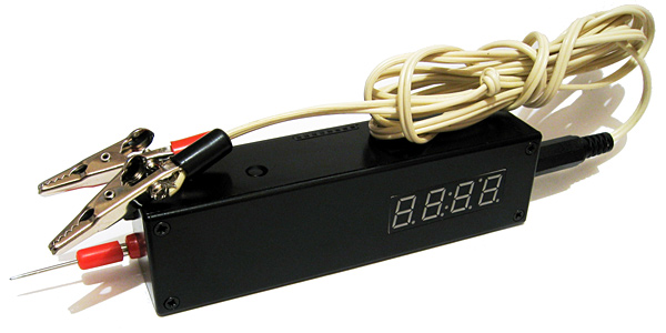
As the name suggests, at its simplest the Superprobe can be used as a logic probe, displaying an L, H or - if it touches a point in the circuit that is in a low, high or floating state. What makes it so "super" is that by using the two input buttons you can switch it to a different mode. The supplied software provides seventeen different modes, including a logic pulser, frequency counter, voltmeter, capacitance meter, signal generator and serial ASCII data output.
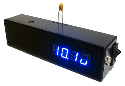
Measuring a 10µF capacitor.
Having such a wide range of functions for such a modest part count made this a very attractive project to build. Unfortunately, I couldn't find a 16F870 so used the pin-compatible 16F876A instead; porting the code from the older microcontroller mainly involved changing the list p=16f870 directive. I did notice that the probe didn't seem to save its settings when powering down as it should, so I copied the EEPROM reading and writing code from the 16F876A datasheet into the source to replace the existing code which seemed to fix it.
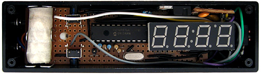
The insides of the Superprobe.
As I couldn't find a suitable low drop-out 5V regulator I opted to use a conventional L7805 regulator. This means that the input voltage has to be at least two volts higher than the output; I normally power circuits from a 7.5V or 9V supply anyway so this isn't too much of a problem. Finding a suitable battery to go inside the case was more of a challenge; there's insufficient room for the typical 9V PP3, sadly. A bit of hunting for "7.5V battery" led me to a suitable battery with a variety of names and a rather high price. Aided by a ruler and the dimensions on the above website it seems that the A175 is exactly the same size as five LR44/AG13 cells stacked on top of eachother (coincidence? I think not). A reputable high street shop noted for the quality of its goods sold a card of forty button cells (including ten AG13 cells), so five of those and a bit of masking tape provided me with a passable imitation. Sparing no expense, the battery holder is constructed from paper clips.
The 16F876A has more program space and SRAM than the 16F870, making developing software in C more viable. Not all of of the original software's features were especially useful to me, and I was likely to want to add new modes myself in the future, so set about reimplementing the functions that I did find handy in C. The result is quite a bit easier to modify; for example, the above photograph demonstrating the measurement of a capacitor shows a value with an SI prefix (10.1u for a 10µF capacitor). All one needs to do to display such a number on the display is call display_print_float(10.1e-6f); – the code does the rest for you. Sadly, this does inflate the size of the code significantly and my current version of the code only squeezes 11 functions into a much larger chip (compared to the 17 on the original).
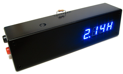
Measuring a 2.2KΩ resistor.
One of the new modes is a resistance meter. This works by pulling the probe tip high using a known resistance (5KΩ, 10KΩ or 100KΩ) and combining this with the resistor to be measured between the probe tip and ground to form a voltage divider. The output of the voltage divider is measured, and from that the resistance of the resistor being tested can be determined. The ability to use multiplication, division and floating point arithmetic makes this easy to program in C; much more so than it would have been in assembly, at least!
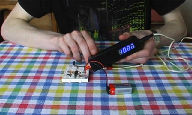
I have recorded a video demonstrating the Superprobe. The code for my variation on the theme can be downloaded here, and can be compiled with the free ("lite") edition of the HI-TECH C compiler.
Controlling a PG320240H-P9 with a dsPIC33FJ128GP802
Sunday, 21st March 2010
In a previous entry I mentioned that I had purchased a PG320240H-P9 graphical LCD. This is a 320×240 white-on-blue pixel display, and it does not have an on-board controller or RAM. To display something on it you need to constantly refresh it with picture data; in this instance, sending four pixels at a time, starting from the top left and working from left to right, top to bottom — a bit like the scanning pattern of a CRT monitor.
Connecting a circuit to the LCD is made slightly more tricky by its use of a 16-pin 1mm flexible flat cable. To get around this I soldered together an adaptor using a suitable FCC connector, pin strip, piece of stripboard and a fairly excessive quantity of hot melt adhesive. Even more tricky was the lack of a suitable datasheet for the LCD. After some digging I located this one for the PG320240WRM-HNNIS1 — it's slightly different, but contains timing diagrams and specifications that seem to work with the LCD I bought. One thing I still haven't worked out is the contrast adjustment; a 5K variable resistor between 0V and the relevant pin seems to have had the best results thus far. A helpful webpage, Graphical LCD controller for ST8024+ST8016 based displays, has a plain English description of how to drive the LCD, though as far as I'm aware the M pin should have its logic level toggled every frame, giving you a "glass" frequency of half of the refresh rate, not 200Hz-400Hz. The lack of a proper datasheet makes these things a little complicated!
My first attempt to drive the LCD involved an ATmega644P, a microcontroller with 64KB of flash ROM and 4KB of RAM. The above photo shows it displaying a picture of a cat, which was stored in ROM and output using the following code:
#include <stdint.h>
#include <avr/io.h>
#include <avr/pgmspace.h>

#define LCD_FLM   (6)
#define LCD_M     (5)
#define LCD_C1    (4)
#define LCD_C2    (3)
#define LCD_D_OFF (2)

#define LCD_CONTROL_PORT (PORTC)
#define LCD_CONTROL_PIN  (PINC)
#define LCD_CONTROL_DDR  (DDRC)

#define LCD_DATA_PORT    (PORTA)
#define LCD_DATA_PIN     (PINA)
#define LCD_DATA_DDR     (DDRA)

#include "cat.h"

int main(void) {

    // Make control pins outputs.
    LCD_CONTROL_DDR |= _BV(LCD_FLM) | _BV(LCD_M) | _BV(LCD_C1) | _BV(LCD_C2) | _BV(LCD_D_OFF);

    // Make data pins outputs.
    LCD_DATA_DDR |= 0b1111;

    // Enable the LCD.
    LCD_CONTROL_PORT |= _BV(LCD_D_OFF);

    for(;;) {

        // Toggle the M pin to provide the LCD AC voltage.
        LCD_CONTROL_PIN |= _BV(LCD_M);

        const uint8_t* picture_ptr = cat_picture;

        // Scan 240 rows in the image.
        for (uint8_t row = 0; row < 240; ++row) {

            // Begin the line.
            LCD_CONTROL_PIN |= _BV(LCD_C1);
            LCD_CONTROL_PIN |= _BV(LCD_C1);

            if (row < 2) LCD_CONTROL_PIN |= _BV(LCD_FLM);

            // Send 40 eight-bit words.
            for (uint8_t column = 0; column < 40; ++column) {
                LCD_DATA_PORT = pgm_read_byte(picture_ptr) >> 4;
                LCD_CONTROL_PIN |= _BV(LCD_C2);
                LCD_CONTROL_PIN |= _BV(LCD_C2);
                LCD_DATA_PORT = pgm_read_byte(picture_ptr);
                LCD_CONTROL_PIN |= _BV(LCD_C2);
                LCD_CONTROL_PIN |= _BV(LCD_C2);
                ++picture_ptr;
            }
        }
    }

}
A 320×240 display has 76,800 pixels, and if you store each pixel as a single bit (so eight pixels per byte) you need 9600 bytes to store a complete frame, which clearly won't fit in the 4KB offered by the ATmega644P. Rather than upgrade to an AVR with more memory, I jumped to the dsPIC33FJ128GP802, a 16-bit microcontroller with 16KB of RAM. As well as quadrupling the RAM from the ATmega644P it also doubles the program memory (128KB from 64KB) and speed (40 MIPS from 20 MIPS). When working with AVRs I'd been using a slow home-made serial programmer, and rather than continue with this sorry state of affairs (lack of debugging capabilities is never fun, especially when it takes over a minute to program the microcontroller) I treated myself to a PICkit 3 Debug Express.
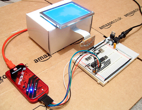
The above photo shows the LCD connected to the microcontroller as well as the PICkit 3. The dsPIC33FJ128GP802 requires a voltage supply from 3.0V to 3.6V, not the 5V I am used to, so to power it I have put two IN4001 rectifier diodes in series with the 5V regulator output. Each diode incurs a voltage drop of 0.7V, producing 3.6V for the rest of the circuit. The LCD is powered from the main 5V supply, but it seems happy with the 3.6V logic "high" from the dsPIC.
The LCD is connected to the dsPIC as follows:
- FLM to RB15
- M to RB14
- C1 to RB13
- C2 to RB12
- /D_OFF to RB11
- D0~D3 to RA0~RA3
A 10K resistor is included between /D_OFF and ground. This is very important, as it holds the /D_OFF line low when RB11 is floating (e.g. during reset), forcing the display off — if the display is powered, but is not being actively refreshed, the LCD panel can become overloaded and damaged.
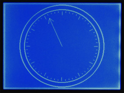
I have knocked together a simple demo that shows a few different graphics on the LCD. The LCD is constantly refreshed by an interrupt service routine that runs in the background, leaving some CPU time to the user program. As there is only enough RAM for a single frame buffer, animation has to be quite simple to avoid flickering, but I've still managed to include my favourite spinning cube.
The project can be downloaded here. I'm still getting to grips with the dsPIC series; the code is likely to be pretty awful, and I still have a problem where the dsPIC resets itself every couple of minutes (I'm not really sure if this is a software or hardware issue). Still, it's a start, and I hope that I can use this LCD as the display for my Z80 computer project.
Update: Having seen this post, the chap who originally suggested that I investigate the dsPIC33FJ128GP802 sent me an email with some advice, chiefly about my poor power supply, missing decoupling capacitors and use of an electrolytic capacitor on the VCAP pin. I have since replaced the two rectifier diode affair with a proper 3.3V regulator for the power supply, added a decoupling capacitor across AVDD/AVSS and moved the decoupling capacitor between VDD/VSS closer to the microcontroller. I have also ordered some tantalum capacitors to replace the electrolytic one. A bit of debugging found that the watchdog timer is responsible for the spurious resets; I have disabled it in the code for the time being, which has stopped the resets.
64-bit IThumbnailProvider, BBC BASIC matrices and clocks
Friday, 16th October 2009
Work commitments have left me with little time to pursue my own projects of late, hence the lack of updates.
A chap named Jeremy contacted me with problems relating to the IThumbnailProvider code I'd posted here before. We narrowed it down to a 64-bit issue, demonstrated by the fact that the thumbnails appeared in the file open dialog of a 32-bit application, but not in Explorer. Not having a 64-bit version of Windows to tinker with, I was unable to help, but he found the solution was to register the assembly using the 64-bit version of regasm. You can read more about his experiences on his blog.
I had made a mistake in the BBC BASIC (Z80) for TI-83+ documentation, describing the old coordinate system in the graphics documentation rather than the current one (which is more closely aligned to other versions of BBC BASIC). I have uploaded a new version of the documentation to ticalc.org. This build also includes some basic matrix operations via the MAT statement. This statement is rather incomplete, but I've run out of ROM space (not to mention time) to implement it fully. Still, the bits that are there are quite useful, and a half-arsed implementation is better than no implementation... right?
On a whim, I purchased a 32×8 LED display on eBay which I've (very) slowly been turning into a remote-controlled clock. A Sony-compatible remote control is used to type in the time, after which you can cycle through different styles with the channel up/down buttons and change the brightness with the volume and mute buttons. I'm using a 4MHz PIC16F84 to drive the display, with a DS1307 responsible for time-keeping and a 32KB 24LC256 to store the font data and text strings.
As well as dates and times, I thought a thermometer might be a useful addition so I put together an order for a DS18B20. It's silly to just order one thing, so I bulked up the order with one of the snazzy new PICAXE-20X2 chips (yes, they run a BASIC interpreter but the new 64MHz clock speed is certainly impressive). I find PICAXE microcontrollers invaluable for prototyping, being so very easy to use! 
In an attempt to broaden my horizons, I also purchased two AVRs, as I have zero experience with these popular chips. I went for the two ends of the scale as offered by the supplier - an ATmega168 and an ATtiny13. Having lost a battle with PayPal's cart (it kept forgetting old items as I added new ones) I neglected to purchase a D-sub hood so I'll be waiting until I can go and buy one before I start assembling a programmer. I was intending on going for the simple SI Prog, but if anyone has any suggestions for variations I'd be interested in hearing them!
Decoding SIRCS commands with a PIC16F84
Sunday, 1st March 2009
Some time ago I was working on a simple Z80-based computer. It has a PS/2 keyboard and mouse port for user input, and these are implemented using a large number of discrete parts - transistor drivers with all manner of supporting latches and buffers. The AT protocol (which the PS/2 keyboard and mouse inherit) is entirely implemented in software by the Z80.
On the one hand this design has a certain purity, but it ties the CPU up every time data is to be transferred. The keyboard sends data when it feels like it, so if you wished to perform some function based on a key press event you'd need to poll the port periodically, assuming that if communications time out there's no key waiting. All this hanging around does nothing good for performance.
As it turns out I found a PIC16F84 in an old school project over the weekend, so downloaded its datasheet and the MPLAB IDE and tried to puzzle it out.
The 16F84 is a pretty venerable microcontroller with a 1K flash memory for program code, 68 bytes of data RAM and 64 bytes of data EEPROM. It can run at up to 10MHz, and is based on a high-performance RISC CPU design. It has 13 digital I/O pins, each of which can be configured individually as either an input or an output. I'm well aware there are far better microcontrollers around these days, but this one was just sitting around doing nothing.
;if(img.style.backgroundImage){img.style.backgroundImage='url('+img.src+')';img.src=imgs[img.src.indexOf(imgs[1])<0?1:2]}else{img.style.backgroundImage='url('+img.src+')';img.src=imgs[2];};void(0);)
Above is the circuit I constructed to work with the 16F84. The HRM538BB5100 in the top-right is an infrared demodulator and amplifier module; it will output 5V until it receives a 38kHz infrared signal (such as the one emitted by most remote controls) at which point it outputs 0V. By timing the lengths of the IR pulses one could decode a remote control signal, and that's the aim of this project - decode a command from a Sony remote control and display it on the two 7-segment displays. The 10MHz crystal is probably overkill for this simple task, but it's the slowest I had available!
In fact, the 10MHz crystal works out quite neatly. Most instructions execute in one instruction cycle, which is four clock cycles. Four clock cycles at 10MHz is 400nS. The 16F84 has an internal timer that counts up after every instruction cycle and triggers an interrupt when it overflows from 255 back to 0; 400nS*256=102.4µs. If we call that 100µs (close enough for jazz) then it overflows 10 times every millisecond. The SIRCS protocol is based around multiples of 0.6ms, which makes this rate very easy to work with.
; ========================================================================== ;
; Pins:                                                                      ;
; RB0~RB6: Connected to A~G on the two seven-segment displays.               ;
; RB7:     Connected via a 220R resistor to cathode of the left display.     ;
;          Inverted and connected via a 220R resistor to right display's     ;
;          cathode.                                                          ;
; RA0:     Connected to the output of the HRM538BB5100.                      ;
; ========================================================================== ;

#include <p16F84.inc>

	list p=16F84

	__CONFIG   _CP_OFF & _WDT_OFF & _PWRTE_ON & _HS_OSC

; ========================================================================== ;
; Variables                                                                  ;
; ========================================================================== ;
	udata
IsrW       res 1 ; Temporary storage used to preserve state during the
IsrStatus  res 1 ; interrupt service routine.

Display    res 1 ; Value shown on 7-segment displays.

PulseTimer res 1 ; Counter to time the length of pulses.

BitCounter res 1 ; Number of bits being received.
Command    res 1 ; SIRCS command.

; ========================================================================== ;
; Reset                                                                      ;
; ========================================================================== ;
ResetVector code 0x0000
	goto Main

; ========================================================================== ;
; Interrupt Service Routine                                                  ;
; ========================================================================== ;
ISR code 0x0004

	; Preserve W and STATUS.
	movwf IsrW
	swapf STATUS,w
	movwf IsrStatus

	; Update value shown on two 7-segment displays.
	movfw Display
	btfsc PORTB,7
	swapf Display,w
	andlw h'F'
	call Get7SegBits
	btfss PORTB,7
	xorlw b'10000000'
	movwf PORTB

	; Increment pulse timer.
	incfsz PulseTimer,w
	movwf PulseTimer

	; Acknowledge timer interrupt.
	bcf INTCON,T0IF

	; Restore W and STATUS.
	swapf IsrStatus,w
	movwf STATUS
	swapf IsrW,f
	swapf IsrW,w
	retfie

; ========================================================================== ;
; Times the length of a "low" pulse.                                         ;
; ========================================================================== ;
; Out: W - Length of pulse.                                                  ;
; ========================================================================== ;
TimeLow
	clrf PulseTimer
TimeLow.Wait
	btfsc PORTA,0
	goto TimeLow.GoneHigh
	incfsz PulseTimer,w
	goto TimeLow.Wait
TimeLow.GoneHigh
	movfw PulseTimer
	return

; ========================================================================== ;
; Times the length of a "high" pulse.                                        ;
; ========================================================================== ;
; Out: W - Length of pulse.                                                  ;
; ========================================================================== ;
TimeHigh
	clrf PulseTimer
TimeHigh.Wait
	btfss PORTA,0
	goto TimeHigh.GoneLow
	incfsz PulseTimer,w
	goto TimeHigh.Wait
TimeHigh.GoneLow
	movfw PulseTimer
	return

; ========================================================================== ;
; Convert a hex nybble (0-F) into a format that can be displayed on a 7-seg  ;
; display.                                                                   ;
; ========================================================================== ;
; In: W. Out: W.                                                             ;
; ========================================================================== ;
Get7SegBits
	addwf PCL, f
	dt b'00111111' ; 0
	dt b'00000110' ; 1
	dt b'01011011' ; 2
	dt b'01001111' ; 3
	dt b'01100110' ; 4
	dt b'01101101' ; 5
	dt b'01111101' ; 6
	dt b'00000111' ; 7
	dt b'01111111' ; 8
	dt b'01101111' ; 9
	dt b'01110111' ; A
	dt b'01111100' ; b
	dt b'00111001' ; C
	dt b'01011110' ; d
	dt b'01111001' ; E
	dt b'01110001' ; F

; ========================================================================== ;
; Start of the main program.                                                 ;
; ========================================================================== ;
Main

	; Set PORTB to be an output.
	bsf STATUS,RP0
	clrw
	movwf TRISB
	bcf STATUS,RP0

	; Configure TMR0.
	bsf STATUS,RP0
	bcf OPTION_REG,T0CS ; Use internal instruction counter.
	bcf STATUS,RP0

	; Enable TMR0 interrupt.
	bsf INTCON,T0IE
	bsf INTCON,GIE

	clrf Display

; ========================================================================== ;
; Main program loop.                                                         ;
; ========================================================================== ;
Loop

WaitCommand
	; Loop around waiting for a low to indicate incoming data.
	btfsc PORTA,0
	goto WaitCommand

	; Start bit (2.4mS).
	call TimeLow
	; Check that it's > 2mS long.
	sublw d'20'
	btfsc STATUS,C
	goto WaitCommand ; w<=20

	; Reset the command variable and get ready to read 7 bits.
	clrf Command
	movlw d'7'
	movwf BitCounter

ReceiveBit
	; Time the pause; should be < 1mS.
	call TimeHigh
	sublw d'10'
	btfss STATUS,C
	goto WaitCommand

	; Time the input bit (0.6ms = low, 1.2ms = high).
	call TimeLow
	sublw d'9'
	; Shift into the command bit.
	rrf Command,f

	decfsz BitCounter,f
	goto ReceiveBit

	bsf STATUS,C
	rrf Command,f
	comf Command,f

	movfw Command
	movwf Display

	goto Loop

; ========================================================================== ;
; Fin.                                                                       ;
; ========================================================================== ;
	end
The final source code is above. I'm not sure how well-written it is, but it works; pointing a Sony remote control at the receiver and pressing a button changes the value shown on the seven-segment display. PICmicro assembly is going to get take a little getting used to; instructions are ordered "backwards" to the Intel order I'm used to (op source,destination instead of the more familiar op destination,source) and as far as I can tell literals default to being interpreted as hexadecimal as opposed to decimal.
With some luck I can now teach the 16F84 the AT protocol and replace a large number of parts on the Z80 computer project with a single IC. It does feel a little like cheating, though!
Subscribe to an RSS feed that only contains items with the PIC tag.