Arcs, segments and sectors in BBC BASIC for the Sega Master System
Tuesday, 12th October 2021
More musing on tape phases
I bought a few more Acorn-format BBC BASIC cassettes to test my adaptation of BBC BASIC to the Sega Master System with, and have found a few interesting oddities since my last post. In that post I made the assertion that the phase of the recorded signals on the tapes is at 180°, i.e. each wave cycle goes negative before it goes positive (whereas a 0° phase would go positive before it goes negative). This matched the documentation I'd read, the output of tools like PlayUEF and my own tests with commercially-recorded tapes. With these new tapes I've found things are not quite so straightforward, though:
- The "Welcome" tape for the BBC Master Series is recorded at 0°. OK, maybe that's a BBC Master weirdness?
- One copy of the "Welcome" tape for the BBC Micro is recorded at the usual 180°, hooray, we're back to normal!
- Another copy of the "Welcome" tape for the BBC Micro is recorded at 0°. It's also a different colour, but otherwise has identical programs on it, maybe the difference comes from different duplication plants?
- Side A of Acornsoft's "Graphs and Charts" is recorded at 180°, Side B of the same tape is recorded at 0°. Flipping the tape flips the phase, I give up!
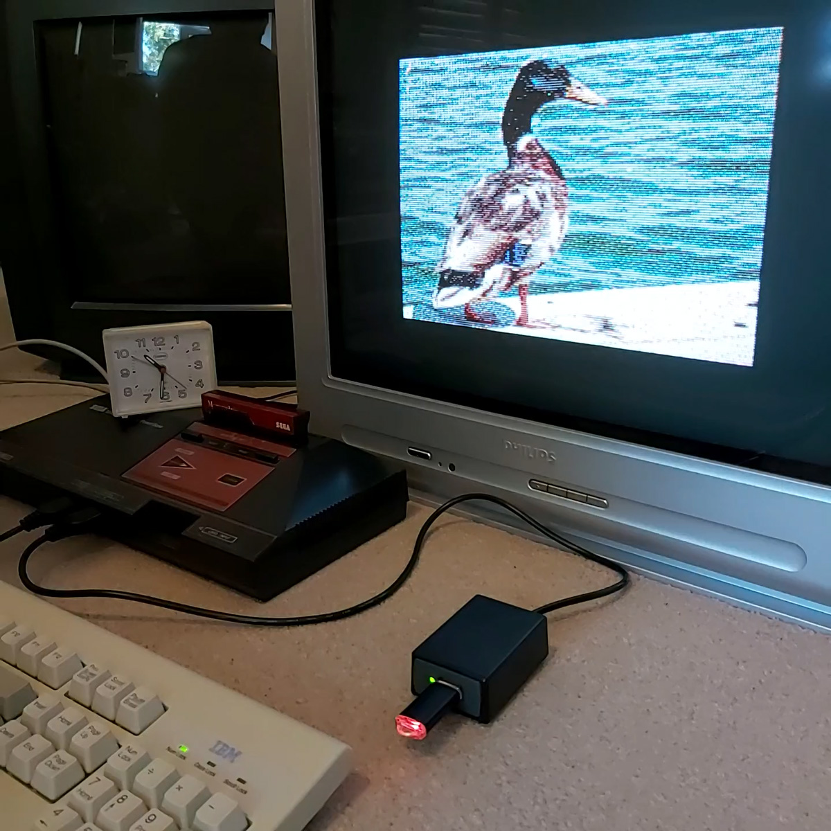
I am able to load the programs by changing the "phase" switch on my cassette recorder to "reverse", but not all cassette recorders have such a switch. There is a jumper setting in the tape interface circuit that the cassette loader software can check to control whether it starts timing the length of wave cycles on a falling (180°, default) or rising (0°) edge and so it can compensate for the reversed phase, but I'd rather see if I can find a way to automatically detect the phase and properly recover data without needing to rewind the tape, push a switch or type in a command, then trying again.
A "1" bit is represented by two 2400Hz cycles and a "0" bit by a single 1200Hz cycle. Each byte has at least one "1" bit before it and always starts with a "0" start bit. In theory, then, a "0" bit with the correct phase should be represented by a wave cycle that's 2× the length of a preceding 2400Hz cycle, but if the phase is incorrect it'll only be 1.5× the length. At the moment the threshold to detect the difference between a 2400Hz and 1200Hz cycle is placed at 1.5×, maybe for the start bit it needs to be at 1.3× to detect the "0" bit instead, and if after that the wave is over 1.6× it's treated as a "normal" 180° tape and loaded as normal, but if it's between 1.3× and 1.6× it's treated as a "reverse" 0° tape and an extra rising edge is checked for before loading the tape with reverse phase.
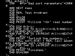
I'm not sure if that'll work and my quick initial tests didn't work very reliably so I'll need to do a bit more experimentation I think. I did encounter another oddity with formats beyond the reversed phase, though, and that's with Acornsoft's "Graphs and Charts". The tokenised BASIC programs on the tape would crash the loader or generate "Bad program" errors, and when I copied the tape to my PC and looked at the files there I could see that BBC BASIC for Windows refused to open them too. The problem is that instead of the usual <CR><FF> terminator on each program, they all end with <CR><80> instead. My loader tries to convert Acorn BBC BASIC format programs to the Z80 BBC BASIC format automatically during the load, but if it misses the terminator when stepping through the program it will either see the line as being zero bytes long (due to memory being cleared to 0) and loop infinitely when attempting to jump to the next line, or read a line length from uninitialised memory that causes it to advance to a line that doesn't start with the appropriate byte and so assume the program is not in Acorn format, skipping the conversion process and leaving a "Bad" program in memory.
I made my loader more robust by appending a suitable dummy terminator to the loaded program; if it already was a valid program with a proper terminator then it makes no difference, but it otherwise prevents the convertor from dropping off the end of the program and allows me to load the programs from the "Graphs and Charts" tape.
Drawing arcs, segments and sectors in BBC BASIC


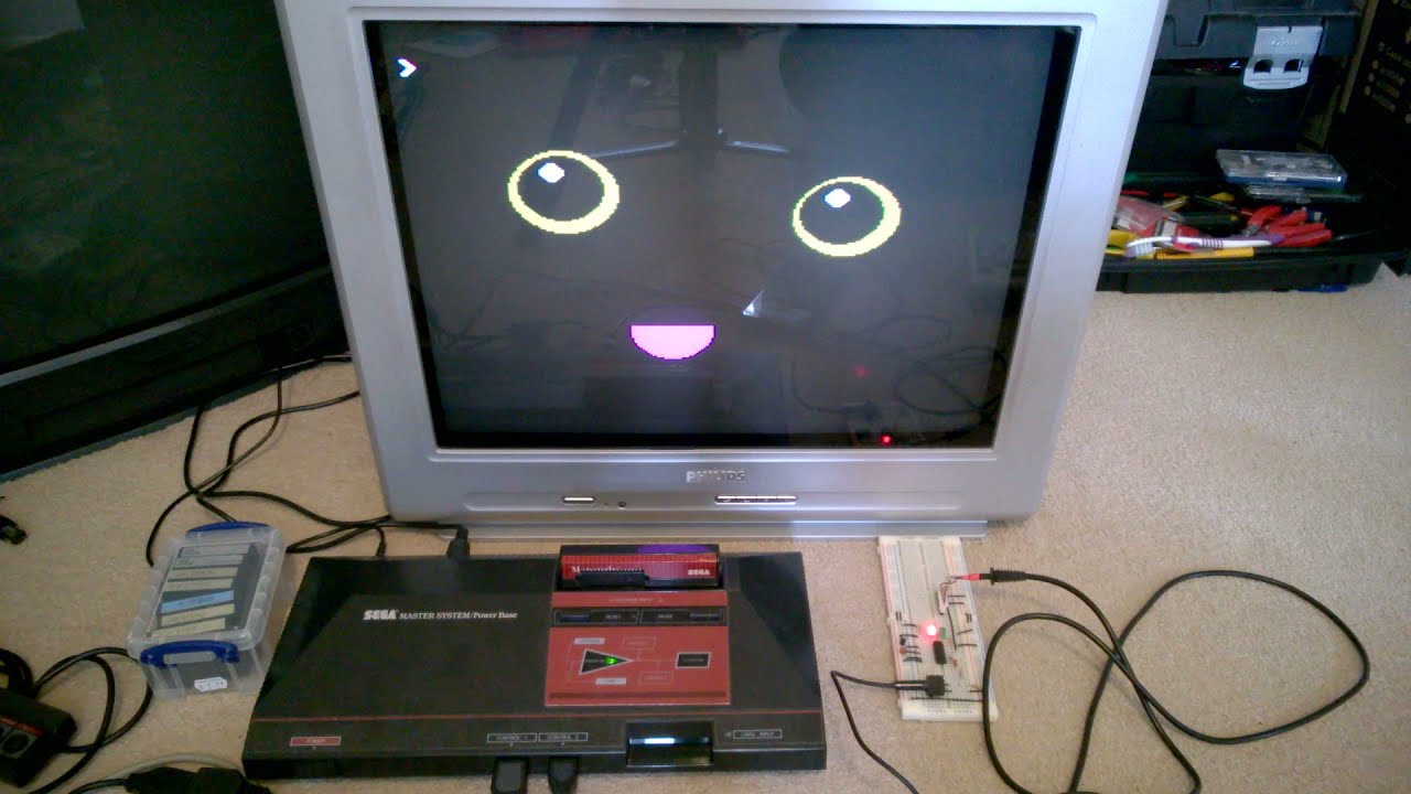
I hadn't implemented all of the PLOTting routines that BBC BASIC can provide for drawing graphics on the screen, and a few of the programs on the BBC Master Series "Welcome" tape take advantage of the more advanced routines to draw circular arcs, segments and sectors. Attempting to run these programs produced results like the picture of the clown above with several parts of its face missing.
I had been putting this off as I hadn't been able to think of a good way to implement drawing these shapes. After a bit more research online I came across a paper by C. Bond entitled An Incremental Method for Drawing Circular Arcs Using Properties of Oriented Lines which turned out to be ideal.
The linked paper does a very good job of describing the technique so I would recommend reading it, but crucially it provides a solution that can be implemented easily in Z80 assembly with a few integer multiplications and additions. I was able to incorporate this into the existing circle tracing and filling code without too much effort, just an extra step in the "plot pixel" or "fill horizontal span" routines to clip against the lines that bound the arc, segment or sector.
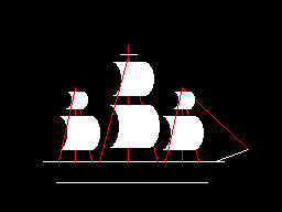
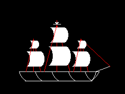


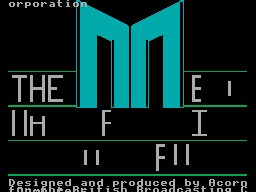
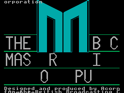
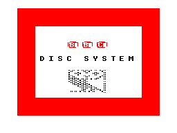
As you can no doubt see from the "Welcome" screen at the end there are still parts missing from the final image. This is because the program only draws each required letter once and then uses the block copying PLOT routines to duplicate the letter if it's needed again instead of rendering it again from scratch – hence the second "B" from "BBC" is missing, and "MASTER" becomes "MAS R" as the program is expecting to copy the "T" and "E" from "THE" in the line above.
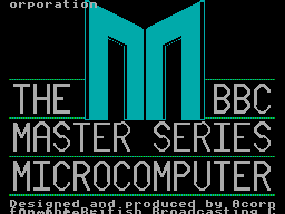
Disabling this optimisation within the BASIC program and forcing each letter to be drawn instead of copied does improve the results, though it still doesn't entirely fit on the screen due to the much lower resolution!
Tape cycle frequencies and phases, plus VDrive3 support for BBC BASIC on the Sega Master System
Wednesday, 6th October 2021
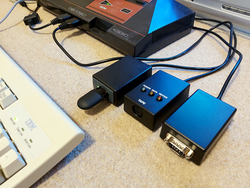
I have now moved the tape interface circuit described in the previous entry from its breadboard prototype to a neat enclosure where I am happy to report it mostly works as well as it did before.
I have spotted two issues, though. The first affects my small cassette recorder but not the large one, and is related to reading files from tape via the file IO routines (such as OPENIN then BGET# to retrieve a single byte, not from LOAD). Files are stored on tape in 256 byte blocks, and when the file is opened a whole 256 byte block is read from the tape and copied to the Master System's RAM. When the BASIC program requests a byte from the tape it is read from this local copy of the block instead, and when the read pointer reaches the end of the 256 byte block the next block is fetched from the tape and the local copy updated with this new data. The motor control comes in handy here, with the file system library stopping and starting the tape playback as desired.
The problem I was having was that the first block would read fine, but when the time came to read the second block the tape started playing but the file system library never seemed to be able to detect any data – it would just work its way along to the end of the tape, never displaying any errors, but never reading any meaningful data either.
The issue ended up being some code I'd added somewhat recently to automatically calibrate the threshold between a 1200Hz ("zero" bit) and a 2400Hz ("one" bit) tone. The code reads bits by counting the length of each wave cycle and comparing this to a threshold value - if it's longer, it's the 1200Hz "zero" bit tone, if it's shorter, it's the 2400Hz "one" bit tone. Before and after each file, and between each block, is a section of 2400Hz "carrier" tone. By detecting a large number of wave cycles that were all around the same length (say, within four length units of each other) you could assume that you were receiving the 2400Hz carrier tone and use that to calculate a suitable threshold for loading in data later.
The main bug was that I was comparing the length of the wave cycle just received with the length of the previous wave cycle rather than the length of the first wave cycle. This becomes a problem when you start a tape that was paused in the middle of a carrier tone (e.g. between blocks) as the tape will take some time to come up to speed, during which time the period of each wave cycle will gradually decrease. As the reference length we're checking the current wave length against is changing over time it means we end up compensating for the tape's speed increasing and so end up accepting the slower (longer) wave cycle lengths as part of the calculation of the threshold between "zero" and "one" bit wave cycle lengths.
As the wave cycle length threshold is now longer than it should be, all incoming wave cycles get interpreted as short ones and so it looks like we're just getting a stream of "one" bits - which looks like the carrier, so the code never starts trying to decode any blocks. My larger tape recorder comes up to speed much more quickly than the small one, or at least doesn't audibly ramp up in speed, and so isn't affected by this problem.
Fortunately the fix is very easy, just check the length of wave cycles against the first wave received rather than the previous one. This way if the timings drift over time (as they would during the period that the tape is coming up to speed) then they'll eventually go out of the permitted range. Changing this fixed the issue.
You may wonder why I'm calculating the threshold at runtime instead of just using a hard-coded value if the expected frequencies are a fixed 1200Hz and 2400Hz. My main intention was to be able to handle tapes that were running at the wrong speed due to a miscalibrated cassette recorder, but this does also open up the possibility to load from tapes at higher rates. Without any further adjustment my code can already load from audio generated at 2320 baud, i.e. with the two frequencies at 2320Hz and 4640Hz, without any further adjustment. This is a slightly annoying figure as 2400 baud would be the obvious target (being double the intended rate!) but at this speed the current code fails to latch on to the signal so I slowed the "tape" speed down until I found a value that worked. It's perhaps worth mentioning that the audio in this case was coming from PlayUEF running on my phone rather than an analogue cassette tape with the BAUD (or LOW) parameter used to adjust the speed, I'm not sure that a 93% boost in loading speed would be achievable from a tape!
I mentioned above that there were two issues. The slow speed-up issue affected the small cassette recorder, but the large cassette recorder had a new issue that only became apparerent after moving the circuit to its final enclosure. The Master System should be able to start and stop the cassette remotely, handled by a reed relay that is then plugged into the cassette recorder's "remote" socket. The Master System was able to start both tape recorders without any issues, but was unable to stop the large one – the "motor" status light would switch off, but the tape would continue playing. Tapping the relay sharply would be the only way to get it to switch off.
I tried plugging in a 2.5mm TS plug into the side of the large tape recorder and used the very scientific approach of shorting its connections with a screwdriver to simulate the relay switching "on" and was surprised to see quite large sparks. I measured the DC current through the remote control switch when the cassette was running and it was only around 70mA at its highest – well below the 1A rating of the relay – however I reckon there is a very large inrush current when the motor kicks in that is sufficient to weld the reed switch contacts together, causing it to get stuck.
Why didn't this affect the circuit on the breadboard? In that setup I was using a 3.5mm TS extension cable connected to a 3.5mm male-to-male adaptor cable which was then connected to a 3.5mm to a 2.5mm adaptor cable. My assumption is that all of the extra contact resistances were helping to limit the inrush current, preventing the contacts from welding together.
It's very likely not the best sort of snubber circuit for this application but for the time being I've put a 10Ω resistor in series with the relay contacts, which limits the inrush current enough for the relay not to get stuck:
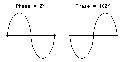
One matter that I've also been testing is the phase of the audio signal. As far as I can tell Acorn's tape format assumes a 180° phase; that is to say that each wave cycle starts at 180° and runs to 180°+360°=540° for a complete cycle rather than starting at 0° and running to 360°. The result of this is that instead of the signal starting at an amplitude of 0, then going positive before negative (as you'd expect for a typical sine wave) the signal goes negative first:
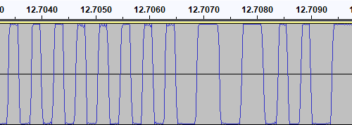
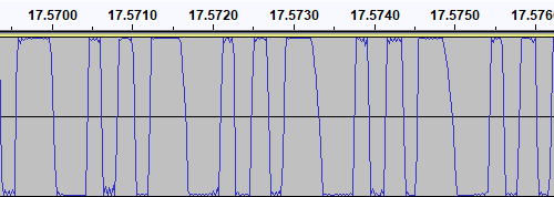
I have confirmed this by looking at the output of tools like PlayUEF as well as looking at the signals coming directly off commercially pre-recorded tapes with BBC Micro software on them, after first confirming that my sound card doesn't invert the signal by briefly connecting its input to a positive DC power supply and seeing that the received signal goes positive when that happens. Here's an example of a commercially-released tape, where you can see that after the high-frequency cycles in the first longer wave (a "zero" bit, acting as the start bit, starting at around 12.7065) starts low then goes high:
I then generated a test tone that alternates between 0 and 1 bits, i.e. one complete 1200Hz cycle then two complete 2400Hz cycles with the appropriate 180° phase:
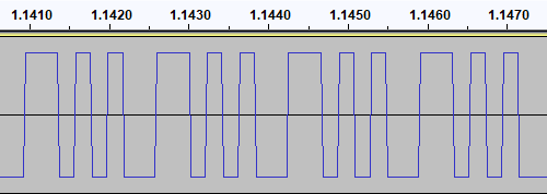
This pattern should make it easy to spot the phase of recordings. I first tried running the test tone straight back into my PC to ensure that the phase was not being reversed by the PC, and got the same signal back in compared to to what I played out, as you'd expect. I then tried recording the signal to tape with my Grundig recorder, and found something interesting when playing it back:
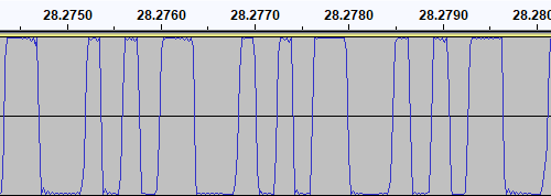
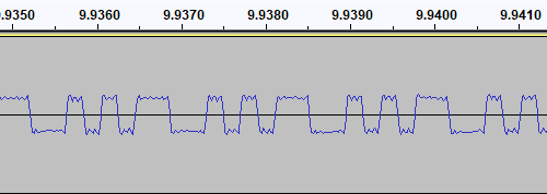
The phase there is very clearly reversed – the signal I played into the tape recorder goes low before it goes high, whereas the signal I've recovered goes high before it goes low. I repeated the test with the Alba tape recorder:
This shows the same thing – the phase on the tape is at 0° even though the test signal was at 180°. I also have a Sony digital voice recorder (an ICD-BX140) that I've been using as well as a tape recorder, so I tried the test with that too:
Apart from the much lower recording level this once again shows the same thing – the signal phase is inverted when recorded.
I had previously encountered an issue where I had tried to make a tape from a UEF image by playing the audio generated by PlayUEF into a tape recorder. Attempting to load the data directly from PlayUEF worked fine, but the tape recording of the same signal wouldn't load. My Grundig tape recorder has a phase reversal switch, and setting it to "reverse" would allow me to load the tape created by recording the output of PlayUEF. However, in that reverse setting, I lost the ability to load from my commercially-recorded tapes. I think the above tests indicate why this is the case – the recorders all invert the signal when creating the tape recording. I find it particularly interesting that the Sony digital voice recorder does the same thing!
I did check to see if the phase switch on the Grundig tape recorder had any influence on the recording, but it doesn't – whether it's set to "normal" or "reverse" the recording to tape still ends up inverted. The phase switch only appears to affect playback.
PlayUEF does have an option to set the output phase to 0° instead of its default 180°. By doing that and recording its output to tape I was able to load the programs directly from either of my tape recorders.
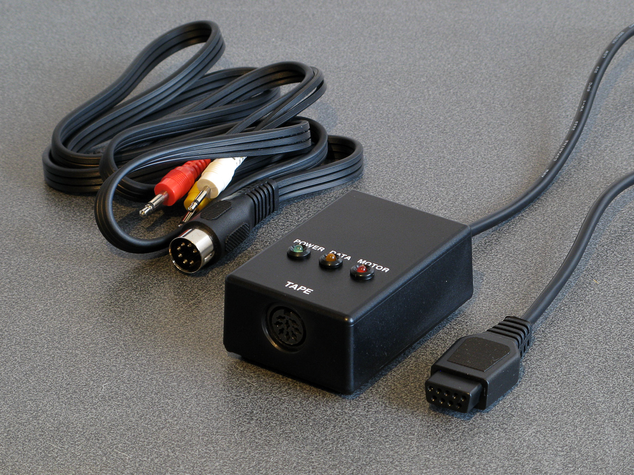
Of course, it would be nice if the loader was able to handle either phase, and in practice I've found it does sometimes handle the "incorrect" phase quite well but it does seem to be more a lot more error prone – some programs load without any problem, others report problems with some blocks and others fail to be detected at all! I think I'll see if there's a way to reliably detect the phase and switch to the appropriate handler, but for the time being I've added a crude workaround – pulling pin 1 of the controller port (the d-pad "Up" input) to ground tells the loader to assume the phase is inverted. As I hope this won't be necessary in future I've left this as a jumper in my current tape interface circuit (visible below in the top left corner) rather than add a switch!
A lot of the work has been focused on the tape loader, but tapes are not the most practical storage media these days. Finding a working tape recorder is a challenge in its own right, and a lot of the old tapes are tricky to work with as they've become sticky with age. In an attempt to be a bit more modern I've started integrating support for the VDrive3 to BBC BASIC. This is an inexpensive module that lets you access files on a USB mass storage device via simple commands sent over a serial interface. I'd previously used the VMusic2 device in another project and that uses the same firmware commands so I already had a little experience with it (the VMusic is pretty much a VDrive with an MP3 decoder bolted on top). I already had some serial routines written so it was a reasonably easy job to plumb in some code to handle LOADing and SAVEing programs, and from a hardware perspective all you need is a cable to connect the module directly to the Master System's controller port – the VDrive3 uses 3.3V signalling levels but its I/O lines are 5V tolerant.
One notable advantage of the VDrive3 over the tape interface is that it allows for proper random-access of files rather than just sequential access. I've been working on implementing all of the required BASIC statements to support this (OPENIN, OPENOUT, OPENUP, BGET#, BPUT#, PTR#, EXT#, EOF#, CLOSE# etc). For a bit of fun I wrote a BASIC program that loads an image file from disk (or tape) and displays it on screen. I needed to add user-defined character support to the new reduced-resolution MODE 2 to handle this (something that was not implemented before due to a lack of VRAM) but with that in place it's working pretty well.
It's not fast, taking 2m45s to load from from tape and 1m19s from a USB flash drive, but it's a fun diversion!
Refining the tape interface for BBC BASIC on the Sega Master System
Tuesday, 28th September 2021
It's been quite a while since my last post but work has continued with the version of BBC BASIC (Z80) for the Sega Master System. Most of the features I have been working have not been particularly exciting to write about on their own, but here are some of the notable changes:
- All VDU code (for text and graphics output) has been moved to a separate ROM bank, freeing up around 16KB of extra ROM space. It makes calling the code slightly more complicated but in the previous post I mentioned that I had less than 100 bytes of free ROM space so this was definitely required.
- Simplified the video mode driver interface. Each video mode has its own driver code which exposes a number of different functions. Previously, each function had its own vector in RAM which was fast but consumed a lot of precious work RAM. Now only a couple of functions (which need to be called frequently and as quickly as possible) are vectored, and all of the other functions are called via a single generic function with a parameter for which specific operation to carry out (e.g. "reset the graphics viewport", "change the text colour").
- Rewrote the triangle filling routine and line drawing routine to ensure that the same pixels are covered whether you fill a triangle or trace its outline – previously there would be some stray pixels that leaked outside the perimeter of a filled triangle.
- Changed the output resolution for most video modes to 240×192 with a logical to physical pixel scale factor of 5⅓ for a total logical resolution of 1280×1024, the same as the BBC Micro – graphics programs designed for the BBC Micro now properly fit on the screen.
- Changed MODE 2 to use a smaller resolution of 160×128 with a pixel scale factor of 8. Unfortunately, there is not enough video RAM to have a unique pattern in VRAM for every character position on-screen when using all 16 colours (as in mode 2) at the higher 240×192 resolution. The new lower resolution avoids screen corruption that previously occurred when running out of VRAM:
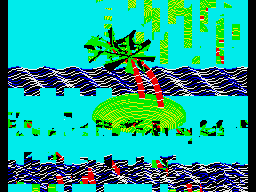
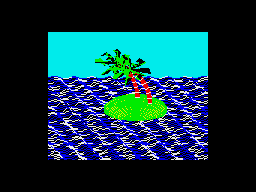
MODE 2 graphics at the full-screen 240×192 and reduced 160×128 resolutions
- Added support for scrolling the text viewport down as well as up, this is used by the line editor which now allows very long lines to be edited in small viewports by scrolling and repainting as necessary.
- Reworked the keyboard input routines for greater reliability and performance, including proper mapping of key codes in *FX 4,1 and *FX 4,2 and removal of "clever" (but flawed) interrupt-based detection of when a key is available (that had a habit of dropping keys and resulted in worse performance than just periodically polling the keyboard anyway).
The most significant changes have been all to do with loading and saving from tape, though. Since my previous post I have been doing a lot of work testing and refining both the hardware and software of the tape cassette interface. The hardware has now been tested with a couple of different tape recorders, as well as a pocket digital recorder, my mobile phone and my PC's sound card. The loader is much more robust and if a single block fails to load from the tape you can usually just rewind the tape a short way and it will try again, no need to rewind back to the start and start from scratch. I was previously counting the duration of half-wave cycles from the tape and comparing these to some fixed thresholds baked into the code to determine the difference between a "0" and a "1", I've now changed this to measure full-wave cycles (which aren't affected by any duty-cycle shifts in the recordings) and to calibrate the thresholds during the initial carrier tone, which allows the code to compensate for tape recorders that aren't quite running at the correct speed. On a more practical basis I've also added the ability to save to tape, motor control via a reed relay (so the tape will automatically stop after a file is loaded), and support for opening files on tape for reading or writing and accessing them on a byte-by-byte basis. As tapes are sequential access there are some limitations to this (for example, you can only advance the read pointer later in the file, you can't seek backwards) but it works quite well otherwise.
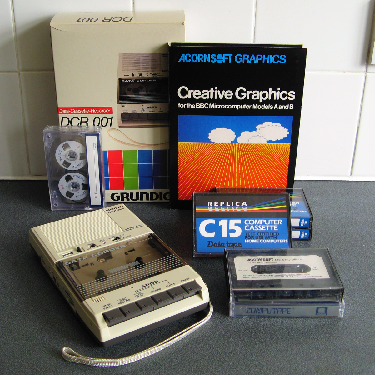
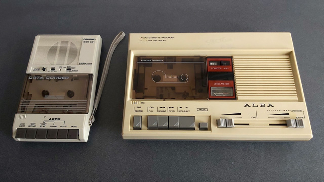
Of course, to test all of this I needed a tape recorder! I purchased the above Grundig DCR 001 data cassette recorder as well as some blank cassettes and a couple of commercially-prerecorded ones to do so. The DCR 001 has a few nice features that make it great for loading programs:
- A dedicated "data" mode that sets the output level at an appropriate fixed level – no need to guess about finding a suitable volume level.
- An optional "monitor" in data mode that lets you listen to the data on the tape as it's loading.
- A "phase" switch that can be used to reverse the phase output, to compensate for the case where the data has been recorded with a 180° phase shift.
- An "Automatic Programme Detecting System" that lets you skip ahead to the next program or back to the previous one by pressing Rewind or Fast Forward when Play is pressed – this stops when it detects a silent gap between recorded sections of data on the tape.
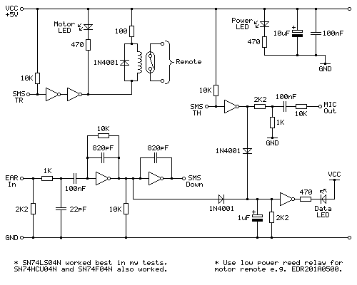
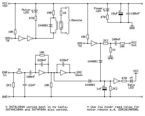
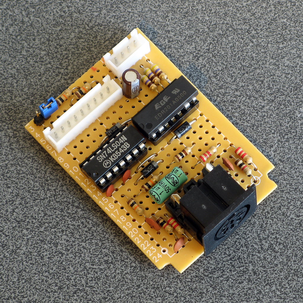
Above is the cassette interface circuit I came up with. It's quite simple and has a notable lack of analogue sections (no op-amp chips here!) – it uses a NOT gate with a 10KΩ negative feedback resistor to turn the analogue signal from the tape recorder's earphone output into a clean digital signal that can be fed into the Sega Master System. I've tested this with an SN74LS04N, SN74HCU04N and SN74F04N and all worked well, however for best results I'd recommend the SN74LS04N. The filtering capacitors clean up some high-frequency pulses/glitches that may otherwise end up on the output; this is not something I found was much of a problem with a cassette recorder or the audio output from my phone or PC, but a pocket digital voice recorder I have seems to produce glitchy high-frequency pulses in its output (I'm not sure if that's an artefact of its DAC or in the MP3 compression it uses for its voice clips) and those capacitors clean up the signal enough to be able to read it reliably.
The remote motor control relay is a reed relay, and must be a low current device to avoid overloading the Master System's controller power supply and to also allow it to be driven directly by the hex inverter chip. I found the EDR201A0500 perfect for this role!
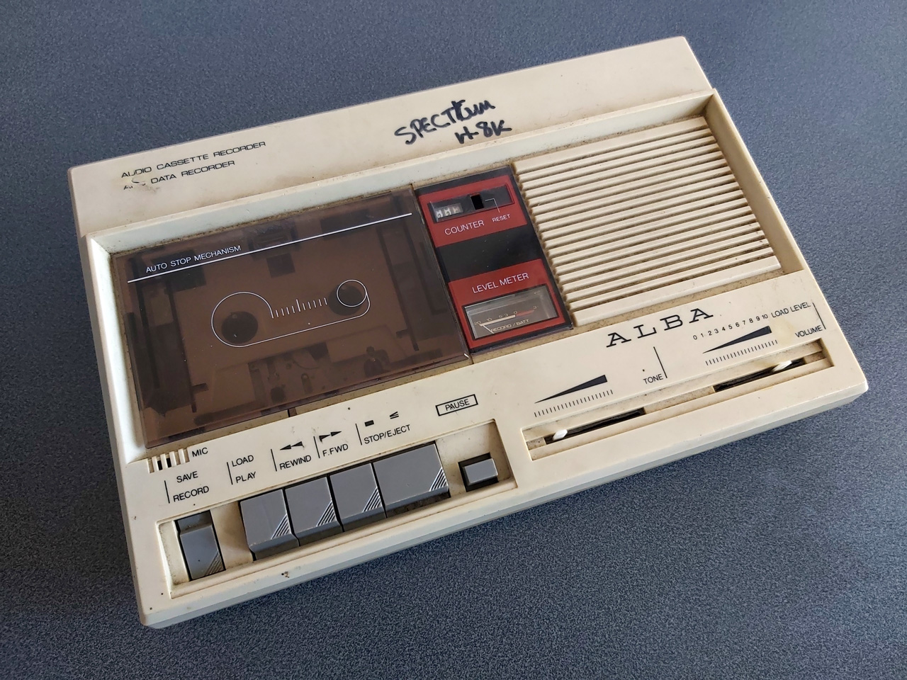
Being able to save and load back programs on one cassette recorder is fair enough, but to really be sure my hardware and software are working as they should I thought I should see if I was able to save a program to tape on one tape recorder and then load the same program back on a different tape recorder. To this end I bought the above cassette recorder. It was clear from the listing that the record button and counter reset button were damaged, and the whole thing was quite grubby, but I thought it worth a punt.
Getting inside was very easy as all but one of the screws was missing, and it was clear that someone had got there before me as the damaged plastic parts (including two of the main screw posts as well as the snapped-off parts of the record button and counter reset mechanism) had been removed at some point. After giving the tape path a very thorough clean and replacing one of the drive belts that was turning into a tarry mess I was able to get it to play a tape, so I took everything out of the enclosure to give that a good scrub and prepared to fix the damaged plastic parts.

By tracing the arm from one of the other buttons onto a piece of scrap ABS plastic I was able to make a replacement arm for the damaged record button, which I then glued on with cyanoacrylate and some two-part epoxy resin to fill in the gaps. The result is not especially pretty but it does the job and my blobby repair is not going to be visible unless you take the recorder apart.

The counter reset button was a bit more fiddly; the reset mechanism seems to rely on the "n" shaped bit of plastic shown above in the top left photo, and though it looked like something used to be attached to it that had snapped off I wasn't sure what it would have originally looked like. I cut up some more scraps of ABS sheet to make up a new counter reset button which seems to work pretty well, though!
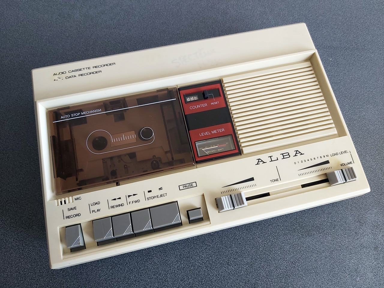
The final addition was a couple of new knobs for the tone and volume sliders – these are cheap generic parts and they don't quite line up with the markings (the original sliders have off-centre indicators) but overall I think this turned out pretty well, and my main concern – being able to save a program to tape on one machine and then load it back from another – has been thoroughly tested now and I'm happy with the results. My next task is to transplant the circuit from its current breadboard layout to a neat project box!
Loading BASIC programs from cassette tape to the Sega Master System
Monday, 16th August 2021
After I posted about the pattern filling modes on Twitter I was alerted to the BBC Micro Bot website which hosts a gallery of programs that produce impressive graphical output from very short BASIC programs (short enough to fit in a Tweet!)
I tried a few of them out but unfortunately ran into problems with a lot of them that use various tricks to reduce the original program text length by embedding non-ASCII characters directly into the body of the program. My usual approach to prepare programs was either to copy and paste them into an emulator (my emulator strips out non-ASCII characters on pasting, as these can't be mapped to keystrokes) or to save them to a file and transfer that serially, and my own editor's tokeniser and BBC BASIC for Windows both had a habit of mangling the non-ASCII characters.

The BBC Micro Bot website does not provide a way to download the BASIC programs directly but does provide a share link that allows you to export a disk image or play back the program from a virtual tape cassette. I don't have a a disk drive attached to my Master System, but the tape option seemed promising...
The basic cassette tape interface
My initial approach to loading programs into BASIC from external storage was to connect my Cambridge Z88 computer running PC Link 2 or EazyLink to the Master System with an RS-232 serial cable. This works well for me, but isn't very practical for others who might not already own a Z88, and I do want this to be an easy project for people to replicate!
Being able to load from tape would significantly lower the barrier to entry, if the cassette tape interface circuit can be constructed easily. You wouldn't even need an actual tape player; the drive belts have gone in mine (I tried to make a test recording on mine and it just unspooled the tape into the bowels of the machine) so for the time being I've been testing loading from PlayUEF, the web-based UEF player that's also found on the BBC Micro Bot website. This can be run from a browser and it works well on my mobile phone and makes loading programs from a web link an absolute doddle. Perfect!
The challenge, then, is how to get that audio data into the Master System in the first place and whether it's got enough grunt to be able to decode it in software. Using the same tape format as the BBC Micro seemed like it would be a good choice so I read this article on the Acorn cassette format on BeebWiki. The highest frequency audio signal is a sine wave at 2400Hz. As we'll need to handle both halves of each cycle we'll need to sample the signal at least 4800 times per second. As the Master System has a CPU clock of around 3.58MHz, that gives us 3.58×10⁶/4800≈756 CPU cycles for each half of the cycle which should be more than sufficient.

We still need to get the audio signal into the Master System somehow! I did a bit of digging online and couldn't find too much information about suitable electrical interfaces. My best lead was the circuit diagram for the BBC Micro's tape interface, however that requires several op-amps and I only have a single LM741 in my parts bin, which isn't going to do a very good job on a single 5V supply. In the short term I've used the circuit above which is a slightly modified version of this common circuit used to convert S/PDIF signals to TTL levels using an unbuffered hex inverter as an amplifier. It's not the most stable circuit and has a habit of oscillating when not fed an input signal but the +5V pullup on the output from the console inhibits this (putting a pull-up or pull-down on any of the inputs changes the mark:space ratio of the pulses). That a load on the output affects what's happening on the input is definitely not a good indication of a properly-functioning circuit, but it'll have to do for now.

I don't know how well it'll respond to a real tape cassette player, but the signal from my PC's sound card or my mobile phone produces very clean square pulses so it should be enough to start experimenting with until I can come up with more stable design.
Decoding the tape signal in software
To decode the signal we'll need to know whether the tape is outputting silence, a 1200Hz tone or a 2400Hz tone. I'm handling this with a simple routine that samples the current level of the input, then loops around waiting for the input level to change state, counting the number of times it takes to go around the loop before the transition. If the counter overflows before the state changes then it's assumed that the tape is outputting silence, but if the state changes before that we can check the value the counter reached to see if it got to a small value (a high frequency signal from the tape) or a large value (a low frequency signal from the tape).
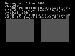
To determine a suitable value for the thresholds I wrote a test program that simply called this routine in a loop 256 times, storing its results in memory, before dumping the results to the screen once all 256 values had been found. By playing a section of the tape in the middle of a data block (so there would be a good mixture of 1200Hz and 2400Hz tones) I got the rather pleasing result that 1200Hz tones appeared to make the counter reach $20 (32) and 1200Hz tones made the counter reach $10 (16), so I put the threshold value between them at 24 as an initial test.
Once we know the frequency of the tape signal at a particular point we can use this to determine the current bit – a "0" bit is a complete 1200Hz cycle (so we'd see two instances of the counter reaching >16) and a "1" bit is two compete 2400Hz cycles (so we'd see four instances of the counter <16). Knowing the bit on its own is not very useful, though, so I added byte decoding which waits for a start bit (0), receives and stores 8 data bits, then checks for a stop bit (1). I could then dump this data to the screen:
At this point the data isn't completely correctly decoded, but it always produces the same results on every run-through which to my mind was a good sign. The text displayed at the bottom of the screen shows some recognisable fragments of the original BASIC program (as the program is tokenised the keywords are missing). The main problem I was having was down to synchronisation; as the article on BeebWiki states "an odd number of 2400Hz cycles can and does occur" and these occasional cycles were throwing me out of sync. The fix was to add an extra check when handling 2400Hz; even though four 2400Hz half-waves are expected, if a 1200Hz half-wave is detected instead it's assumed that we've gone out of sync and the bit should be decoded as a complete 1200Hz pulse instead. After making this change more recognisable text started coming through, so I was able to move on to decoding the data blocks.
Decoding data blocks on tape
Files on tape are broken up into multiple data blocks, each with a header describing the block (e.g. file name, block number, data length) followed by a variable amount of data (up to 256 bytes) containing the data itself. To load a file from tape each incoming block has to be handled. If the block number is 0 then that's the start of the file, so the filename is checked. If this matches the supplied filename (or the supplied filename was the empty string "") then the loader switches from "Searching" to "Loading" mode and the data we just received is stored in memory. From that point on each incoming block is appended, as long as the block name and number match what we expect (i.e. the same filename as before but the block number should be the previous block number + 1). This continues until the "end of file" block flag is set. A CRC-16 of the received data is also checked after each block to ensure that the data has been received successfully. If there are any errors (the block name/number doesn't match what was expected, or the CRC-16 check fails) then an error message is printed and you can rewind the tape a bit to try receiving the block again.
This doesn't sound too complicated, but I've not had too much luck implementing this successfully. My code is currently a bit of a mess and doesn't properly maintain the "Loading" or "Searching" states which means that if an error occurs at any point then it can get a bit confused trying to resolve it (to the point where it's easier to just abort the load and start again from the beginning). However, the tape block issues are not the only problem...
Conflicting BASIC program formats
The programs I'm trying to load are designed for the BBC Micro, where programs are stored in the Acorn or "Wilson" (after Sophie Wilson) format. However, BBC BASIC (Z80) was written by Richard Russell and therefore uses the "Russell" format. Both have a lot in common, fortunately but the way each line is stored in memory differs (this is covered in more detail in the "Program format" article on BeebWiki). Fortunately the formats are similar enough that it's possible to convert them reasonably trivially in-memory.
My initial plan was to leave the loaded program as it is, and to provide a star command (e.g. *FCONVERT, named after the FCONVERT.BBC program) to convert from the "Wilson" format to the "Russell" format. Unfortunately, after loading the file BBC BASIC (Z80) checks the program and applies its own fixes to it, notably writing the appropriate terminator on the end of the program. As far as I can tell it does this by following the program along, line by line, until it finds what it believes is the end. In the "Russell" format the first byte of the line is its length, and in the "Wilson" format it's a carriage return (value 13). What I think this means is that BBC BASIC (Z80) thinks that the second line of an Acorn program should occur 13 bytes in, and as this isn't likely to be the case it ends up writing its terminator 13 bytes in to end the first line. This prevents me from fixing loaded programs after the fact, as they've already had part of their contents overwritten.
Instead, I've added a check to the program after I've loaded it but before I've returned control to BBC BASIC. If I am able to read the program from start to end in "Wilson" format then I apply the conversion to "Russell" format automatically. In practice this means that both file formats load correctly, but I don't particularly like the way that if you LOAD a "Wilson"-format file then SAVE it back it'll be saved as a "Russell"-format file.
There are still some differences in the formats and the way they're tokenised but usually that can be fixed by loading the problematic lines into the line editor (*EDIT) and pressing Return without making any changes. This forces them to be retokenised and has fixed some of the issues I've run into.
Another issue is that "Wilson" format BASIC files support a line number 0, but "Russell" format ones do not; the file will be loaded and can be run, but if you try to LIST it then it'll stop when it reaches line 0 (which is usually the first one!) so programs appear to be empty. This is not something I think can (or indeed should) be fixed automatically but if necessary you can change the line number for the first line from 0 to 1 with ?(PAGE+1)=1 so there is at least one solution.
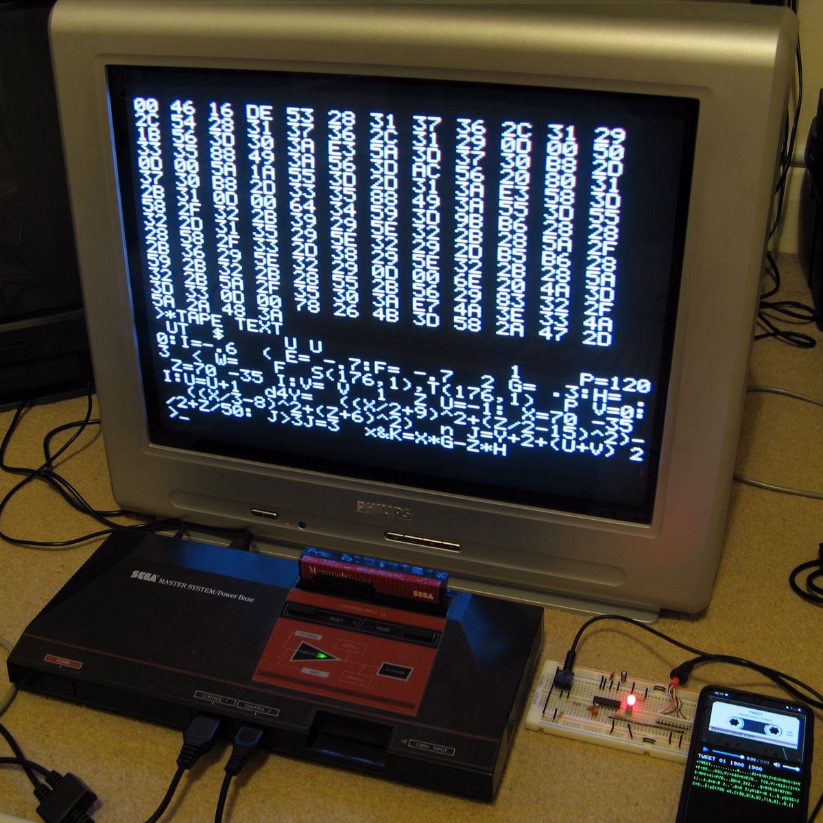
The video above shows a couple of programs being loaded from the BBC Micro Bot website onto the Master System. Even with the terrible audio to digital interface it gets the job done! The 7905=7905 messages at the end of each block during loading show the CRC-16 calculated for the received data followed by the expected CRC-16, as they match it indicates the data is getting through successfully.
Emulating the tape interface
As alluded to above my current loading system works well enough when everything is OK but it gets a bit confused when there's a fault. I never really planned out how to handle this and the code's a bit of a spaghetti mess in places so I drew out a flowchart of a more robust loader, which itself is also a bit of a mess but hopefully one that will make loading tapes more user-friendly and robust.
Unfortunately, doing any work on this interface has been very tedious as every time I make a change I need to try it on real hardware – I don't know of any Master System emulators that include tape support! I've been using my own Cogwheel emulator throughout which is itself not a very good emulator (there are no proper debugging tools, for example) but I can at least bolt on weird features I need like PS/2 keyboard emulation, so I thought it would be a good use of my time to add tape interface emulation. I started by writing a UEF (Unified Emulator Format) parser that could turn a UEF image file into a 4800 baud bitstream that could be fed into the Master System's controller port. For some reason my files end up being slightly different lengths to the sound files generated by PlayUEF – nothing major, but a handful of seconds over the length of a roughly 7 minute file. I tried loading the generated bitstream as a 4800Hz sample rate file into Audacity and it didn't quite line up with the audio file generated by PlayUEF either, but after poring over the specifications for the UEF format I was unable to figure out where the discrepancy lay.
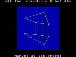
Undeterred I pressed ahead and added this simple cassette player to the emulator, which happily seems to work well in spite of the reported timing differences:

One thing that's notable there is that the program CIRCLE2 appears in the catalogue on-screen. When I first added the cassette interface emulation it was missing, but it would not be detected on real hardware either, which made me quite happy! Being able to more rapidly make and test changes to the tape loader code I was able to experiment and found that the tape loader seemed to miss the synchronisation byte ($2A) sent at the start of block headers on the CIRCLE2 program. This seemed to be due to going out of sync with the bit stream in the period between detecting the carrier tone and the first start bit, so I changed the code to demand exactly two 1200Hz half-waves as the start bit rather than using my more lax code that decodes the contents of the main bit stream that allows for extra 2400Hz pulses. This ensures that the start bit is always properly synchronised, and after making this change CIRCLE2 appeared in the catalogue as it should. I then reflashed the ROM chip on the cartridge and tried on real hardware, and that now picks up CIRCLE2. Being able to fix a problem that appears on hardware by replicating and resolving the same issue in software emulation justifies the few hours I spent adding the cassette tape emulation!
Unfortunately, I'm down to under a hundred bytes of free program space on the 32KB ROM I've been developing with, and I still have a lot of features I'd like to add (including the more resilient tape loader). I've been trying to put this moment off as long as possible as I'm going to have to use bank switching to map in additional memory banks, and that means a lot of difficult decisions about what code lives on which ROM pages to minimise the amount of switching that's required. Conventionally slot 2 is used as the slot to map different banks into but at the moment that's where I've mapped in the cartridge RAM to extend BASIC's memory. On the plus side very little of my code needs direct access to BASIC's memory (I mostly use my own data storage or the stack which lives at the top end of memory, far above slot 2) so this would seem like a good fit but I currently allocate storage space in BASIC's free memory for some operations (e.g. as temporary space when copying data around the screen during scrolling operations) so I'll need to change that code to use memory allocated elsewhere. It's not the most glamourous part of the project, but it'll need to be done if I am to add all the features I'd like.
Patterned fill modes for the Master System version of BBC BASIC
Tuesday, 10th August 2021
One of the features I was quite happy with in the TI-83 Plus version of BBC BASIC was the dithered fills used to provide some semblance of different colours. Sixteen different patterns were provided between black and white:

As well as baking in the sixteen different dithered patterns I added a command that let you use your own pattern tile in a very hacky method (you'd allocate the memory for the pattern via DIM and then pass the address of that memory to GCOLPAT – the extra "PAT" statement after GCOL is what did the trick).
What I didn't realise at the time is that the BBC Micro also had support for patterned fills via its Graphics Extension ROM and a much more natural way to interact with it – GCOL 16,0, GCOL 32,0, GCOL 48,0 and GCOL 64,0 let you select one of four pattern slots, and you can redefine the patterns with VDU 23,2,… to VDU 23,5,… followed by 8 bytes of pattern data, similar to how user-defined characters are already programmed.
Armed with the Graphics Extension ROM's user manual and sample programs I went ahead and implemented these patterned fills in my four- and sixteen-colour modes. Here's the output of the "shades" program, which runs in a four-colour mode and generates dithered fill patterns for the triangle to simulate different shades:


Depending on the number of colours of the screen mode you're currently in the 8×8 bitmap used as a fill pattern is interpreted differently; in the 16-colour mode it represents a 2×8 pattern that is repeated four times horizontally, in 4-colour mode it represents a 4×8 pattern that is repeated twice and in 2-colour modes it's a complete 8×8 pattern with no repetition. I like the idea of these 8×8 patterns so added a new two-colour video mode, mostly based on the existing four-colour mode but with the palette limited to two colours and the revised rules on interpreting fill patterns. This produces results like the following from the "pattern" demo program:


I've also implemented VDU 23,11,… (it resets the four patterns to their initial values) and VDU 23,12,… to VDU 23,15,… – these are helper commands that let you populate a fill pattern from a 2×4 list of colour values that is then repeated across the specified pattern number regardless of the current screen mode and without you needing to perform the bitwise arithmetic to pack the different colour values into memory properly. You may have also noticed that the four patterns are spaced sixteen GCOL numbers apart from each other (16, 32, 48, 64) – this is because you can use these pattern fills in conjuction with the logical plotting modes, e.g. GCOL 16+1,0 will OR the pattern over the existing screen contents.
These pattern fills apply to all graphics operations, so if I break out of the shaded triangle program above when it's settled on a particularly garish palette and switch to outputting text as graphics with VDU 5 I get results like the above. I'm not sure how practical or useful that would be but it does at least show how flexible the graphics plotting system is.
Better plotting modes, text anywhere on the screen and double-height characters for Sega Master System BBC BASIC
Monday, 9th August 2021
I've made quite a few changes to the way colours and plotting modes are handled in the Sega Master System version of BBC BASIC; previously this was handled on a per-graphics-mode driver basis, but this resulted in a lot of duplicated code and some inconsistencies. The new code is a bit more straightforward but also adds quite a few new features, most obviously different plotting modes:
Plotting with the OR mode
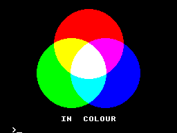
The above screenshot shows the result of filling three circles with the OR plotting mode. The red circle is colour 9, the blue one is colour 10 and the green one is colour 12. Where the colours overlap they are ORed together when drawing, so for example red OR blue is 9 OR 10 which is 11, the colour code for magenta, hence the colour between the two is magenta. Where all three colours mix, that's 9 OR 10 OR 12 which is 15, the colour code for white.
It's the logical colours (the palette indices) that are combined by these plotting operations, rather than the RGB values, it just happens that the stock palette lines up neatly with the RGB values!
Another addition I've made is support for VDU 5. In normal operation, text sent to the display is displayed at the text cursor position. In VDU 5 mode the text is instead drawn at the graphics cursor position, which allows text to be drawn anywhere on the screen, outside the confines of its usual grid. It also takes into account the graphics plotting modes mentioned above and so you can blend text with other graphics operations. Here's an example:
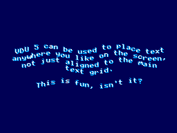
The somewhat blurry text has been drawn in two passes slightly offset from one another, once with colour 1 and again with colour 2, ORed together so that where the text overlaps you get colour 3, which is white. The program for this is as follows:
 10 REM Draw wavy text in a watery style.
 20 MODE 2
 30 REM Set up a suitably watery palette.
 40 COLOUR 0,0,0,64
 50 COLOUR 1,0,64,128
 60 COLOUR 2,0,128,255
 70 COLOUR 3,255,255,255
 80 REM Draw text at the graphics cursor position.
 90 VDU 5
100 REM How many lines of text will we draw?
110 RESTORE
120 L%=-1
130 REPEAT READ L$
140   L%=L%+1
150 UNTIL L$=""
160 REM Draw in two passes, slightly offset, in OR mode for a blurry effect
170 FOR C%=1 TO 2
180   GCOL 1,C%
190   RESTORE
200   Y%=(960+L%*50)/2
210   REPEAT READ L$
220     IF LEN(L$)>0 AND L$<>"-" PROCWAVES(L$, C%*4, Y%-C%*4)
230     Y%=Y%-50
240   UNTIL L$=""
250 NEXT C%
260 REM Restore normal text operation.
270 VDU 4
280 REM Wait for a key then exit.
290 REPEAT UNTIL INKEY(0)=TRUE
300 REPEAT UNTIL INKEY(0)<>TRUE
310 END
320 REM Draw some wavy text at X%,Y%
330 DEFPROCWAVES(TEXT$,X%,Y%)
340 LOCAL I%
350 X%=X%+(1280-(LEN(TEXT$))*35)/2
360 FOR I%=1 TO LEN(TEXT$)
370   MOVE X%,Y%+20*SIN(X%/80+Y%/160)
380   X%=X%+35
390   PRINT MID$(TEXT$,I%,1);
400 NEXT I%
410 ENDPROC
420 REM Text strings to display.
430 DATA "VDU 5 can be used to place text"
440 DATA "anywhere you like on the screen,"
450 DATA "not just aligned to the main"
460 DATA "text grid."
470 DATA "-"
480 DATA "This is fun, isn't it?"
490 DATA
When you're finished you can use VDU 4 to return to the normal text mode. In the video modes where I've had enough free VRAM to spare for it I've also added support for user-defined characters. You can send 23, then a character number, then eight bytes of pixel data for the 8×8 character bitmap to the VDU and then use that data for subsequent text operations (the characters from &80..&FF can be redefined). These user-defined characters can also be used as 8×8 sprites when combined with VDU 5.
I'm having quite a lot of fun writing my own test programs but it's also been useful to be able to run existing software as a test. I've tried to improve my sound handling and it now sounds a bit more faithful to the BBC Micro (though the Master System is a slower machine, so it can't quite keep up with more adventurous pieces of music).
The BBC Disc System "Welcome" screen and the Bones demo
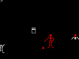
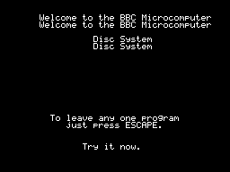
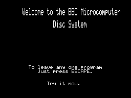
With the new graphics plotting modes and VDU 5 support the BBC Disc System "Welcome" program runs, for example, though it looks a bit rough around the edges due to mismatches in the video modes. Bones also runs, however the mismatch is even more severe here and half way through the skeleton turns red as it's running in the four-colour video mode and COLOUR 1 is mapped to red, not the white in the monochrome mode the demo is expecting. The misalignment comes from differences in the number of rows and columns of text that are available; the demo mixes graphics commands (which are mapped reasonably closely to the BBC Micro's screen) and text; if the demo expects the screen to be 40 columns wide and the best I can offer with this hardware is 32 columns, it won't line up! Of course, the BASIC program can be tweaked to get it working properly, but it's fun to see just how close it gets without any tweaking...
One recurring issue, however, is with programs that expect to be able to use Teletext features. The BBC Micro's default video mode used a Teletext character generator, which allows for bright colourful text and some limited graphics support in very little memory. I had previously mapped this mode to the TMS9918A text mode, which allows for 40 characters in 24 rows, just one row short of the BBC Micro's 40×25. It's a fast mode and is good for program editing due to the large number of text characters on screen at a time (all other modes are 32×24) however it is very limited - there's no support for colour, for example, other than the global foreground and background colours.
To provide some colour support I loaded the character set into memory twice, once normally and once inverted, so via the COLOUR statements it's possible to inject some variety into this mode. The BBC Micro's Teletext MODE 7 doesn't support the COLOUR statement, it relies on embedding special control codes in character positions on the screen that affects the rendering of the rest of the text in the line – for example, a command might change the colour, or cause the rest of the line to flash. As I can't possibly support such codes, I just ignore them, and the programs run fine but look a bit bland.
The main exception to this, I've found, is the double-height text mode. You can switch this on within a line by storing the value 141 in a character cell and then off again with 140 afterwards. This will only display the top halves of the characters, so to display the bottom halves you need to output the same content on the line below. A lot of BBC Micro programs seems to take advantage of this feature, so most programs I'd tried ended up having doubled-up text like you can see in the screenshot above.
The character set I'm using is only 96 characters long (32-127) but I had avoided investigating this as I assumed I'd need to triple the number of characters - the regular-height ones, plus the top and bottom halves of the doubled characters. 96×3=288 which is more than the 256 characters we have available, so I didn't think this would fit.
However, I did think that maybe some characters shared parts - for example, the top halves of the colon and semicolon are the same, and the bottom halves of the semicolon and comma are the same, so I wrote a quick program to count how many unique patterns would be needed and found that it would only take 225 patterns in total, well within our 256 pattern budget!
I set up a new video mode based on the original TMS9918 text mode. This generates these 129 additional patterns for the double-height characters when initialised, and also checks the nametable when outputting characters to see if there's a "double height" control character in the same line to determine whether it should pick one of the stretched characters (picking a top or bottom half depending on whether there are an even or odd number of lines above it that also contain the double height control character).
This new mode does lose the inverted text, but I think the double-height text will be more useful in practice – or at least is better at making programs look less broken!
A four colour any-pixel-addressable video mode for the Master System
Wednesday, 4th August 2021
The video display processor in the Sega Master System is derived from the TMS9918A and provides a number of different screen modes. These modes are mostly character-based and generate the picture that is displayed on your TV based on two blocks of data in video RAM: the name table, which specifies which character appears in each cell on the screen and the pattern generator which contains the pixel data for each character.
TMS9918A "Text" mode
The "Text" mode is probably the most straightforward example. Only two colours can be displayed on the screen; a foreground and a background colour, both selected from a fixed palette of 15 colours. The name table is 40 cells wide and 24 tall. Each cell, or text position, is a single byte that refers to one of 256 patterns in the pattern generator, so the complete name table is 960 bytes long. Each character is displayed as 6×8 pixels but the data in the pattern generator is eight pixels wide, and each row is stored as a single byte with a set bit selecting the foreground colour and a cleared bit selecting the background colour (the two least-significant bits are ignored). Each character pattern therefore takes up 8 bytes of VRAM, or 2,048 bytes (2KB) for a complete set of 256.
The "Graphics I" mode changes the character size to be the full 8×8 pixels at the expense of the number of characters that can be displayed per line; this is reduced from 40 to 32, so the name table is now 32×24 and 768 bytes long. The pattern generator is the same size as before and you can still only display 256 unique patterns on-screen at a time, but there is at least some provision for colour. The top five bits of the character/pattern number are used as an index into a 32-byte colour table, where each colour table entry contains two four-bit values corresponding to the foreground and background colours for the pattern. This means that patterns 0-7 share the same two colours, patterns 8-15 have the next set of two colours, 16-23 after that and so on; 256 patterns, in groups of eight with a different pair of colours assigned to each of those 32 groups.
TMS9918A "Graphics II" mode
Fortunately, the TMS9918A is a revised version of the original TMS9918 which adds the much more useful "Graphics II" mode. The name table is the same as before, 32×24 cells of one byte each, and the patterns are still 8×8 pixel bitmaps. However the pattern generator table is now three times the size, storing 768 unique 8×8 patterns in 6KB. To be able to address all 768 patterns when you can only store values from 0-255 in the name table the screen is divided into three sections; the top third references the first 2KB of the pattern generator (patterns 0-255), the middle third references the second 2KB of the pattern generator (patterns 256-511) and the bottom third references the last 2KB of the pattern generator (patterns 512-767). This allows every single character position in the nametable to reference a unique pattern, and therefore have a bitmap that covers the entire screen area.
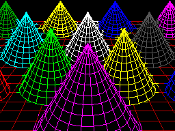
The colour table has also been significantly improved. Instead of one pair of colours for each group of eight patterns, each pattern now gets its own table of colour pairs, one per row. This doesn't allow every pixel on the screen to have its own colour, but you can at least give each 8×1 region its own pair of colours. This does lead to attribute clash when drawing; you can see this in the screenshot of the cones above, where the colour from some lines bleeds into the colour set for nearby lines if they happen to pass through the same 8×1 pixel block.
Very few Master System games use the TMS9918A video modes (F16 Fighting Falcon seems to be about the only concrete example), instead using a new video mode added specifically for the Master System. This has a number of nice new features (such as hardware scrolling and two user-definable 16-colour palettes instead of a fixed 15-colour one), but it's the name table and pattern generator that's of main interest. Instead of having a separate bitmap for the pattern and its colour table, each pattern is now a 32 byte object where each 8 pixel row is encoded as four bytes, one byte for each bit of the four-bit colour palette index. That is, if you wanted to store the top row of a pattern where the leftmost pixel was set to palette index 1, the rightmost pixel was set to palette index 15 and everything else was left as 0 it would be stored like this:
.db %10000001
.db %00000001
.db %00000001
.db %00000001
The second row would then follow with another four bytes, all the way down to the bottom row for the complete 32 byte pattern. This scheme allows you to set each pixel in every pattern to any of the sixteen colours per palette, so if you could fill the screen with such patterns then it would be possible to set any pixel on the screen to any of sixteen colours, solving the attribute clash problem. Unfortunately, to do so would take 768 patterns (32×24), and if each pattern is 32 bytes then that would take up 24KB of video RAM. The Master System only has 16KB of video RAM, which would limit you to 512 patterns, so it's not possible to fill the screen with unique patterns. In practice you can't even have 512 patterns, as you still need to store the name table in video RAM, and as each name table entry has been inflated to two bytes (which does at least let you index pattern numbers above 255 without splitting the screen into thirds as per the Graphics II scheme) that leaves even less room for patterns.
In practice you are limited to 448 patterns, which is not enough to cover the screen. As you will generally start from a blank screen and then add to it, the name table could be filled with blanks by default and then as you draw over the screen of it new patterns could be allocated as required. This is how the graphics currently work in the 16-colour Master System video mode, and it allows for colourful drawings with no colour clash as long as you don't fill too much of the screen.

Cautious use of the 16-colour Master System mode
That's the mode the sphere above is rendered in; you can see there's fine detail at its North pole without becoming subject to colour clash and it doesn't fill so much of the screen that we ran out of unique patterns to allocate. As it would be very bad to run out of patterns when attempting to draw text the character set (the 96 characters from 32-127) are permanently allocated as unique patterns which further reduces us to 352 tiles for graphics output.
It's possible to constrain the graphics viewport via VDU 24 to a smaller region which would ensure you never needed more than 352 tiles, as long as your new viewport was properly aligned to the 8×8 grid. For example, 22×16=352 which means that you could have a 176×128 pixel graphics window that you could draw to without risking running out of patterns.
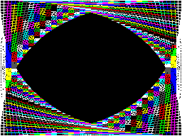
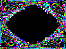
Colour clash in Graphics II (left) versus running out of tiles in Master System Mode (right)
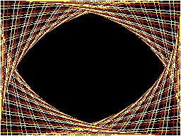
The two screenshots above show the trade-off between colour clash in Graphics II and corruption due to running out of patterns in the 16-colour Master System graphics mode, both caused by running this program:
 10 INPUT "Mode",M%
 20 MODE M%
 30 FOR I%=0 TO 47
 40   GCOL 0,I%
 50   X%=(I%/47)*1279
 60   Y%=(I%/47)*959
 70   MOVE X%,0
 80   DRAW 1279,Y%
 90   DRAW 1279-X%,959
100   DRAW 0,959-Y%
110   DRAW X%,0
120 NEXT I%
130 REPEAT:UNTIL INKEY(0)=-1
140 REPEAT:UNTIL INKEY(0)<>-1
Having to worry about your pattern budget isn't really in the spirit of fun and experimentation. If we're up against hardware and memory limitations I'd rather have a slightly less capable video mode that does at least generate correct output however you use it.
It is possible to completely avoid colour clash if you use the Graphics II mode and simply never use any colour commands, but only having two colours is a bit drab. With a bit of tinkering I came up with another graphics mode that is still using the Master System mode, but reduces the number of colours down to 4. Quite fittingly, a lot of BBC Micro screen modes only supported four physical colours, so I set this new mode to use the same black/red/yellow/white palette by default:
Four colours on-screen at once, no clash and no corruption
In fact, the palette is the whole key to this solution. You may recall that the Master System mode supports two 16-colour palettes. Usually one is assigned as the "background" palette and the other as the "sprite" palette, however each entry in the name table contains a flag that lets you specify which palette the selected pattern should be shown with. In this new video mode, the top half of the screen is assigned to patterns 0-383 using the "background" palette, and the bottom half of the screen is assigned to the same set of patterns 0-383 but to use the "sprite" palette. The palette is then filled with four colours, like this:

Using all 32 palette entries to display four colours on screen simultaneously
The top row is the "background" palette and shows the four desired colours repeating in order four times. The bottom row is the "sprite" palette, and shows that each of the four colours is stretched to fill four consecutive palette entries. This use of repetition effectively turns two bits in each pattern's bitplanes into "don't care" values, depending on which palette is selected.
For example, assume we're in a pattern assigned to the "background" (top) palette and we want to display red. This is colour %01, but as the red entry is repeated we could use use any of colours %0001, %0101, %1001 or %1101 and they'll all come out red – we don't care about the top two bits.
Alternatively, we could be in a pattern assigned to the "sprite" (bottom) palette and want to display yellow. This is colour %10, but it fills the entire palette block from %1000 to %1011, so again we don't care what the lower two bits are, just what the top two bits are.
Using this somewhat redundant palette, we can pack two different four-colour patterns for different parts of the screen into a single sixteen-colour pattern. It's a shame that a halving in bit count ends up quartering the number of colours but I think it's an acceptable solution considering the hardware limitations.
Better drawing, editing, memory and emulation for BBC BASIC on the Sega Master System
Tuesday, 3rd August 2021
I have continued to work on the Sega Master System version of BBC BASIC, and it's feeling much more like a practical version of BASIC than something that was just holding together to run one specific program!
One of the key improvements is to standardise the handling of the different graphics modes. Previously I was using a coordinate system where (0,0) is in the top left corner and all drawing operations were carried out using physical device coordinates (so the screen was treated as being 256 pixels wide and 192 pixels tall). I have now moved the origin (0,0) into the bottom left corner with the Y axis pointing up and scale down all coordinates by 5, effectively making the screen 1280 logical units wide and 960 units tall. This isn't 100% compliant, as the BBC Micro and other versions of BASIC treat the screen as being 1024 units tall, but dividing by 5⅓ is considerably trickier and it would result in the graphics being squished further vertically, so I think using a logical resolution of 1280×960 is an acceptable compromise. I've added some VDU statements to allow you to move the graphics origin as well as define custom graphics and text viewports, so you can control where on the screen graphics and text appear and how they are clipped/scroll.

The output of the "Mandelbaum" program following these changes
I have also changed the default palette to more closely match the one used by the BBC Micro and other versions of BBC BASIC. This isn't too difficult when using the Master System's "Mode 4" as that has a user-definable palette, but the legacy TMS9918A modes have a fixed palette so I've tried to match the default palette as sensibly as I can to the TMS9918A palette. It's possible to change the logical to physical palette mappings under Master System "Mode 4" via a VDU command which writes directly to the CRAM (you can either remap one of the 16 logical entries to one of the stock 16 colours, or supply an RGB value directy to select additional colours) which allows for neat tricks like palette cycling, but the TMS9918A modes currently only let you change the current text/drawing colour, not amend the palette as that's fixed in hardware.
I've also added filled/outlined circle and axis-aligned ellipse PLOT commands using some code written by Darren "qarnos" Cubitt which I originally used in the TI-83 Plus version of BBC BASIC. This code is very capable and fully accepted 16-bit coordinates for its inputs, however it was also originally designed to output to a 96×64 pixel screen so the final plotting was done with 8-bit coordinates ranging from -128..127. Fortunately the Master System's screen also fits in 8-bit coordinates at 256 pixels wide but that's not quite enough information as you also need to be able to tell if a particular point is off-screen (less than zero or greater than 255); simply clipping it against those boundaries will result in a vertical smear on the left or right edge of the screen when drawing outlines. Fortunately I was able to figure out how to modify his code to add some extra clipping status flags to ensure that ellipses were clipped and displayed correctly on any part of the screen.

Filled circles and filled/outlined ellipses make these drawings possible
The only graphics operation exposed by the mode-specific drivers before was a simple "set pixel" routine. This is fine for lines but quite slow for filling shapes so graphics mode drivers can now supply a "fill horizontal span" routine for faster shape-filling. If the routine is left unimplemented a stub routine is provided that fills the span using the "set pixel" routine.
I also added a rectangle-filling PLOT command, which is perhaps not the most exciting-sounding graphics operation but it is used to clear the screen so it is at least useful. More interesting is a triangle-filling routine, something I've never enjoyed writing!
Usually I get very bogged down in the idea that the pixels affected when you fill a triangle should exactly fit within the pixels that are outlined by drawing lines between each of the triangle's points, no more and no less. This can be a bit difficult when the triangle is filled by tracing its edges from top to bottom and drawing horizontal spans between them. If the edge is "steep" (its overall height is greater than or equal to its width) then this isn't too bad, as there's only one X coordinate for each Y coordinate where a pixel would have been plotted. However, when the edge is "shallow" (its overall width is greater than its width) there are going to be certain Y coordinates where the line drawn would have had multiple pixels plotted. In that case, where is the boundary of the horizontal span?
The cop-out answer I've used in the past has been to set up three buffers the total height of the screen and to "draw" the three lines first using the same line-drawing algorithm as the line PLOTting command, keeping track of the minimum and maximum X coordinate for each Y coordinate. When it's time to fill the triangle the minimum and maximum X coordinate for each edge can be determined based on the current Y coordinate and a span drawn between them for perfect triangles. On the TI-83 Plus this takes up four bytes per line (minimum and maximum 16-bit values) for a 64 pixel tall screen, with three buffers for the three lines that comes to 4×64×3=768 bytes, pretty bad. On the Sega Master System that would be 4×192×3=2304 bytes, totally unacceptable on a machine with only 8KB total work RAM!
Each face of this 3D sphere is filled by two triangles.
I've instead simply done my best to interpolate from one X coordinate to the other when working my way down the triangle and filling scanlines, doing a bit of extra pre-incrementing and fudging of initial error values depending on whether it's the top half or bottom half of the triangle. My test was to draw the outline of a triangle in bright white and then to fill a dark blue triangle over the top, if any bright white pixels were visible around the outside this indicated a gap. I mostly got it filled, but I then tried my test program on a BBC Micro emulator and found the BBC Micro exhibited similar gaps so I don't think I'm doing too badly! The above screenshot of the 3D sphere was rendered using this triangle-filling code.
I've also been working on improving the line editor. This is called by BASIC when it's asking for a line of text input from you. Previously I'd only implemented adding characters to the end of the line and pressing backspace to remove characters from the end of the line; if you'd typed in a long piece of code and made a mistake at the start you'd need to backspace all the way to the mistake, correct it, then re-type the rest of the line. Now you can use the cursor keys (or home/end) to move around within the line, insert or overwrite new characters (toggled by pressing the insert key on the keyboard) at the cursor position or backspace/delete characters mid-line as required. It sounds like a small thing but it was quite a lot of code to get right and makes a big difference for usability!
Another feature I've added to aid modifying lines of code is the *EDIT command. This takes a line number as an argument and then brings up the program line you've requested in the line editor, ready for editing. The way this works is a bit sneaky, as it's not natively implemented by BBC BASIC! The trick that makes it work is the ability to override two routines, OSLINE (which BASIC calls when it wants to display the line editor) and OSWRCH (which BASIC calls when it wants to output a character).
When a valid *EDIT <line> command is entered, OSLINE is overridden with the first custom routine. This routine doesn't ask for a line of input, but instead copies L.<line> to the input buffer, overrides OSWRCH with a routine that captures data to RAM, overrides OSLINE with a second custom routine, then returns. BASIC therefore thinks you've typed in a LIST statement so it dutifully starts outputting the line via OSWRCH, but this has been overridden to write the characters to RAM rather than the screen. When it's done this BASIC then calls OSLINE again for the next line of input, which brings up the second custom OSLINE handler. This pulls the data from RAM previously captured by the OSWRCH handler, copies it to the OSLINE buffer, and dispays it on-screen as if you'd just typed it in. It then restores the original OSLINE and OSWRCH handlers before jumping back into the stock OSLINE routine, so you can continue editing the line that you'd requested via *EDIT.
All of this hopefully makes entering programs via the keyboard less cumbersome. Of course, not having to type in programs in full every time you wanted to run them would be even better, and an attempt to give BASIC more memory provides another way to load programs in a somewhat roundabout manner.
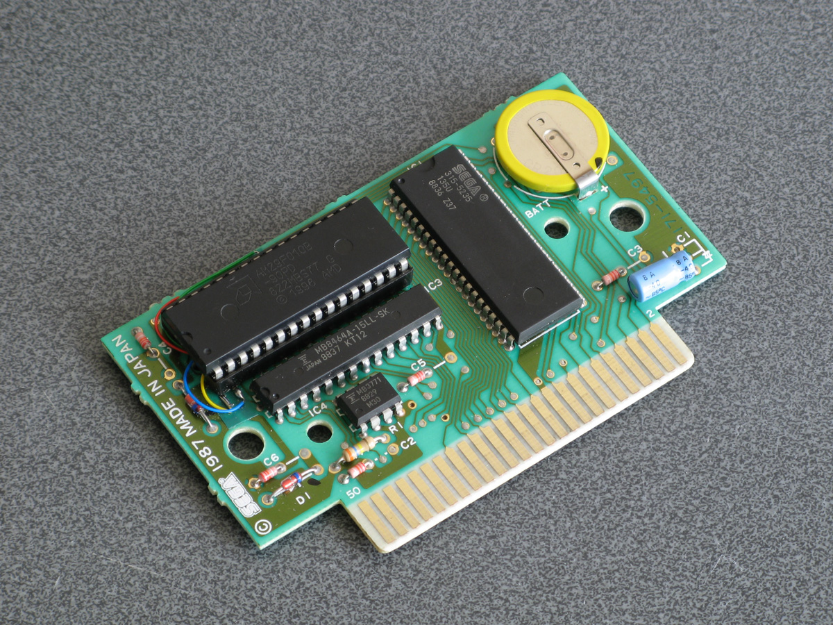
The photograph above shows the modified Monopoly cartridge that I'm now using to test BBC BASIC on real hardware instead of the modified After Burner cartridge I was using before. The advantage of Monopoly is that it has an additional 8KB RAM on board, which is used to save games in progress. Sega's cartridge mapper allows for on-cartridge RAM to be mapped into the address range $8000..$BFFF, immediately below the main work RAM which is at $C000..$DFFF. If present, then, BASIC's memory range (which runs from PAGE to HIMEM) can be extended by enabling the save RAM and moving PAGE down.
$8000..$BFFF is a 16KB range, though, and I mentioned that Monopoly has an 8KB RAM. This is true, and what it means is that the 8KB cartridge RAM is accessible from $8000..$9FFF but is then repeated ("mirrored") from $A000..$BFFF. The cartridge RAM detection therefore has to check two things: firstly that there is RAM in the first place (which can be verified by modifying memory at $8000 and seeing if those values stick) and how big it is (which can be checked by writing to $8000 and seeing if that has also modified the data at $8000+<RAM size>). Once presence of any RAM has been determined during startup, RAM mirroring is checked in 1KB, 2KB, 4KB and 8KB offsets. If any RAM mirroring is detected, then it's assumed the RAM is the size that was being checked at the time, however if not it's assumed that the RAM is the full 16KB. At this point, PAGE (which is $C000 in a stock machine with no cartridge RAM) is moved backwards by the size of the detected cartridge RAM, e.g. to $A000 for an 8KB RAM and $8000 for a 16KB RAM. This results in 16KB or 24KB total available to BBC BASIC, a considerable upgrade from the plain 8KB work RAM!
An added bonus of this is that when you type in programs they grow upwards in memory from PAGE. As PAGE now starts within your cartridge memory, and that cartridge memory retains its contents courtesy of a backup battery, it means that if your entered program is smaller than the size of your cartridge memory you can restore it when you switch the console back on by typing OLD.
That's very well for life on real hardware, but I continue to do most of my development testing in an emulator. I'm having to use my own emulator as there aren't any other Master System emulators that also include a PS/2 keyboard emulator, but I did end up running into a very weird bug. Certain trigonometric functions in BBC BASIC were producing very wrong values, resulting in very odd-looking output.


These shapes are on the wonk
Even though the Z80 emulator at the heart of the program passed ZEXDOC (an instruction tester that checks documented functionality) I remembered that it had failed some aspect of ZEXALL which checks the undocumented flags too. I re-ran ZEXALL and found the problem was with my implementation of the bit instruction, so I worked on fixing that including emulation of the Z80's internal temporary memptr/WZ register to ensure that bit n,(hl) set bits 3 and 5 of the flag register appropriately. ZEXALL now passes, but unsurprisingly it didn't fix my problem (as I didn't really think that BBC BASIC would rely on undocumented functionality!)
I ended up isolating certain exact values that when plugged into SIN() or COS() would produce incorrect results. I then dug out my old CP/M emulator and tried plugging those values into the generic CP/M version of BBC BASIC (which has none of my code in it!) and that produced the same, incorrect, results confirming that the issue was definitely in my Z80 emulation and not in some flaw of the BBC BASIC port.
After tracing through the code and dumping out debug values at certain points and seeing where it differed to a known good reference emulator I found that the fault occurred in FMUL, and from there I found that at some point the carry flag (which is either rotated or added to registers with RR or ADC instructions) was being lost. RR looked fine but digging into my implementation for the 16-bit ADC I found the culprit: the code is the same for ADD and ADC, but in ADC if the carry flag is set then the second operand is incremented by one first. This produces the correct numeric answer, but if the second operand was $FFFF on entry to the function then adding a carry of 1 to it would cause it to overflow back to 0. As this happens before any of the rest of the calculations are made it means that the final value of the carry flag was calculated based on op1+0 instead of op1+$10000, hence the loss of the carry flag.
Fortunately, fixing this fixed the wonky output demonstrated above and I feel slightly more confident in my emulation! Now I can continue working on BBC BASIC, I've had an idea for a screen mode that has a reduced number of colours but will hopefully let you draw anywhere on the screen without running out of tiles causing odd corruption (as happens in the usual 16-colour mode 4) and without attribute clash (as happens in the TMS9918A Graphics II mode)...
Running BBC BASIC on the Sega Master System
Thursday, 22nd July 2021
I've recently been spending some time finding a way to run BBC BASIC on the Sega Master System, inspired by BASIC Month 6: The Mandelbaum Set on the RetroBattlestations Reddit community.
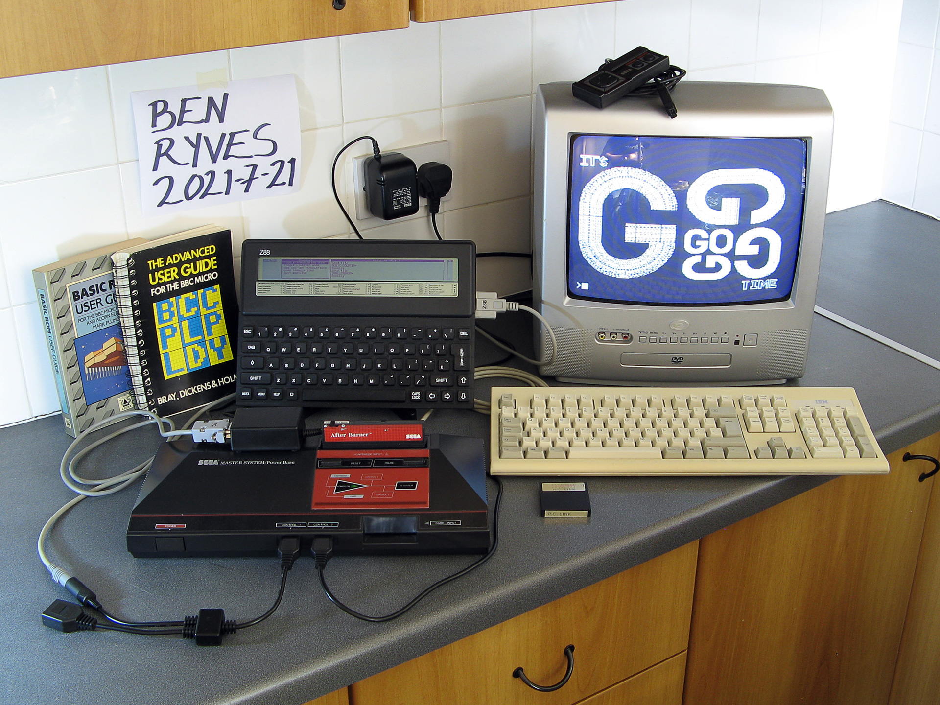
When this month's program was first announced I tried running it on my only unarguably retrobattlestation, my Cambridge Z88, but the screen's low (vertical) resolution didn't do the program much justice.
I thought this gave me two options:
- Control some external piece of retro tech to produce higher-resolution output (e.g. a printer or a plotter.
- Port a BASIC interpreter to another retro system with a higher resolution display and run the program on that.
Unfortunately, I don't own any old printers or plotters (or a Logo-like turtle!) so option 2 seemed my best option. I had some experience adapting Richard Russell's BBC BASIC (Z80) to run on the TI-83 Plus calculator so I thought I should pick the Sega Master System as that also has a Z80 CPU in it. Here are some rough specs:
- 3.58(ish)MHz Z80 CPU.
- 8KB work RAM.
- TMS9918A-derived VDP for video with 16KB dedicated VRAM accessed via I/O port.
- SN76489-derived PSG for sound.
- Two controller ports with six input pins and two pins that could be configured as inputs or outputs.
- Software loaded from ROM cartridge or card slot with a small BIOS ROM that detects whether a cartridge or card is inserted (and if not, runs its own built-in game).
There is some precedence to this endeavour with the computer version of Sega's SG-1000, the SC-3000, which came with a keyboard and had BASIC ROM cartridges.
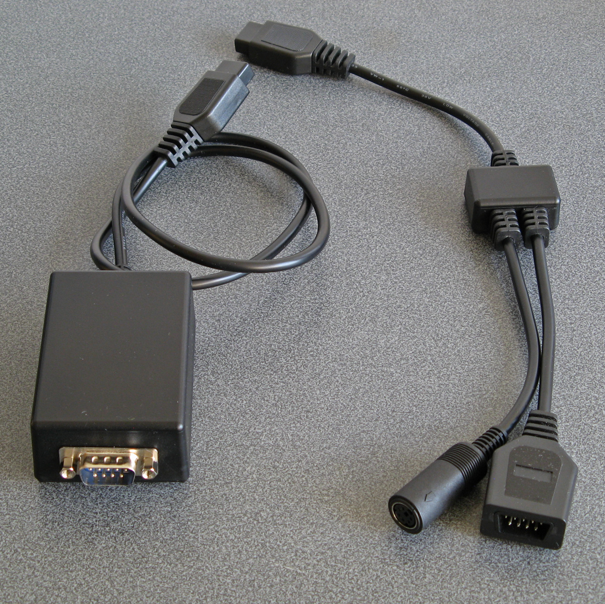
I wanted to try to keep this project as retro as possible, so no modern microcontrollers as I've been accused of cheating by using them in the past. I did have to make a couple of adaptors to allow me to plug in a keyboard and to give the Master System a serial port to load or save programs over – more about these later!
Loading BASIC onto the Master System
The first problem was getting BASIC onto the Master System at all. As my Master System doesn't have BASIC in ROM (it comes with Hang-On, which is perhaps more fun but less likely to handle the Mandelbaum set) I'd need to load the program onto a cartridge or card. Master System cartridges usually contain a mapper circuit to handle bank switching in the lower 48KB of the Z80's address space (the upper 16KB contains the 8KB work RAM, appearing twice) which is normally integrated directly into the ROM chip for the game, however there are a handful of games that have separate mapper chips and ROM chips and the ROM chips that Sega used have a pinout that is extremely close to that used by common EEPROMs (e.g. 29F010,
49F040) with only a couple of pins needing to be swapped around. After Burner is one such cartridge, so I've modified an old copy to let me plug in flash memory chips that I can program with the version of BASIC I'm working on. A switch at the top of the cartridge lets me switch back to the original pin configuration if I want to play the original copy of After Burner.
Typing commands into BASIC
With a flashable cartridge to hand I was able to assemble a version of Richard Russell's BBC BASIC (Z80) with some simple code stubs in place to direct text output to the screen. Output is useful but only half the story, we still need to be send commands to BASIC!
The Master System doesn't have its own keyboard, so I'd need to find some way to interface one to it. I have previously used PS/2 keyboards in a number of projects, as they are pretty simple to deal with. Electrically, they use two open collector I/O lines for bidirectional data transfer (one as clock, one as data), and fortunately each controller port of the Master System has two pins that can be configured as outputs which can therefore be used to interface with a keyboard (either left as inputs and pulled weakly high in their idle state, or driven low as outputs for their active state).

It acts as a pass-through cable so you can still have a regular controller plugged in when using the keyboard.
The two pins on the Master System control port that can act as outputs are TH and TR; TH is normally used by light guns to latch the horizontal counter in the video chip so is unused with normal controllers so it's no great loss here, but TR is the right action button (marked "2") so by using this pass-through adaptor you do unfortunately lose one of the controller buttons. However, you do gain a hundred or so keyboard keys, so I don't think it's too bad a compromise...
For the software side of things I adapted my Emerson AT device library, previously written for the TI-83 Plus calculators, to the Sega Master System hardware. This library handles the low-level AT device protocol and also translates the raw keyboard scancode values to the corresponding characters.
Saving and loading programs
At this point I was able to type in BASIC programs and run them on the Master System, which was pretty neat! However, I was still working on adding new features (e.g. drawing commands for graphics) and having to type in the entire Mandelbaum program after every change was going to get pretty exhausting. I could bake it into the ROM but that seemed like cheating, so I thought I should try to find a way to load the file from an external source. A floppy disk or tape cassette would seem authentically retro but adding a floppy drive controller to the Master System would be a fairly complicated task and I don't have a suitable data cassette recorder to even attempt loading from tape so I thought some sort of file store accessible over a serial port would be a good option.
The Z88 has a serial port and can act as a remotely-controlled file store when running the PC Link software (with the protocol documented here. This seemed like a good choice, if not for the fact that the Sega Master System doesn't have a serial port of its own. To get around this, I added one, using a MAX232 chip to adapt the Master System's 5V logic levels to RS-232 compatible ones so I could plug in a null modem cable from the Z88 or my PC without accidentally frying the Master System with -12V.
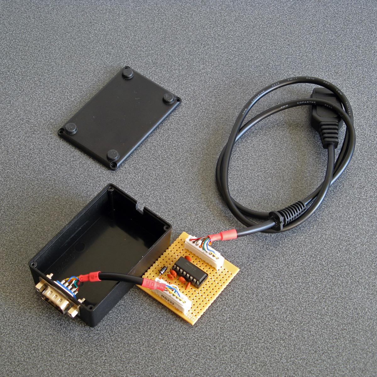
I wrote some code that bit-bangs the serial data over the controller port lines using the timing loop code I wrote for a previous BASIC Month (Crisps Tunes) to support rates between 19200 and 300 baud. 19200 baud is somewhat unreliable but that's OK because the Z88's 19200 baud is unreliable too, so the default 9600 baud speed does a good job. RTS/CTS handshaking has to be implemented, as there is no hardware serial support on the Master System and it needs to be actively polling the port to receive any data. In doing so I noticed one awkward fact about my PC's serial port - if you de-assert RTS it will continue sending data until its buffer is empty, presumably only checking the RTS line when it's about to top up the buffer. In practice this means that even if I change RTS virtually as soon as the start bit for the first byte is received, the PC will continue to send up to 256 bytes before stopping. To get around this I added a serial receive buffer that immediately checks for the next byte even after asserting RTS, and this seems to have done the trick.
The protocol used by PC Link requires acknowledgement after every single byte so is very slow but at least it's reliable. I plumbed the PC Link code into BASIC's LOAD and SAVE which makes loading and saving programs as transparent and easy as if you had a floppy disk in the system instead!
Pressed for size
The Master System has 8KB of RAM. Of this, 16 bytes are mapped to special hardware functions and BBC BASIC reserves 768 bytes for itself, so we're already down to 7,408 bytes. I initially reserved 256 bytes for my own needs (display settings, VDU command buffer, serial port status, keyboard status etc) bringing it down to 7,152 bytes. The 16KB of display memory is not directly accessible to the CPU, so it can't be used for additional work RAM, and having to access it indirectly via I/O ports is very slow but I can't afford to mirror parts of it in RAM for speed.
Initially the Mandelbaum program ran well enough by stripping out comments, but I then added sound support (with eight 13-byte envelope definitions, and four channels with their own state, copy of their active envelope and a command queue for 32 bytes per channel, adding around another 140 bytes of memory usage) and the program stopped running with a "No room" error during execution (performing a square root operation, of all things!) so I guess the tolerances were very tight. I went and combine more lines of code into single lines and replaced two-letter variable names with single-letter ones (no, really) and it was able to run again but I don't think 8KB is a particularly comfortable amount of RAM for a BASIC computer!
Further design considerations
The version of the BASIC host interface used here is very much a work-in-progress. I would need to extend it considerably to be useful, including:
- Fuller support of different VDU commands, e.g. redefining character shapes, changing the text and graphics viewports, better colour handling (differentiating between logical palettes and physical palettes).
- Better support of other modes (so far only TMS9918A "Text" and "Graphics II" modes are used, there is a Master System-specific "mode 4" but that lacks graphics support and only takes advantage of hardware scrolling for extremely fast program LISTing).
- Implementation of more graphics commands - so far only PLOT 4 (MOVE) and PLOT 5 (DRAW) are implemented. They also use a non-standard coordinate system with (0,0) in the top left of the screen and a screen resolution of 256x192, whereas for standardisation with other BBC BASIC implementations this should move (0,0) to the bottom left and use a logical resolution of 1280x1024 or similar.
- Support of other file systems rather than rely on a Z88 running PC Link, e.g. using I²C EEPROMs (as they use two open collector pins, so could be plugged into a controller port via a passive adaptor).
- Support of extra RAM, either integrated directly on a custom cartridge or using the battery-backed SRAM supported by some other cartridge types.
- Native controller support via BASIC ADVAL command (at the moment you can access the controller ports directly with GET(&DC))
This is before even getting into adding anything machine-specific (e.g. to take advantage of scrolling tilemaps or hardware sprites), but getting the BASICs down (and consistent!) is a very important starting point. Consistency is useful, after all I was able to get the original program running under BBC BASIC with very minimal changes to it.
But, in the short term, I have at least succeeded in what I set out to do, which was to run the Mandelbaum program on a retro "computer" wholly unsuited to it!

The above video provides another demonstration of the setup – playing the Cold Tea music demo, albeit with a heavily stripped-down version of the visuals as the Master System doesn't have anything that can match the capabilities of the BBC Micro's teletext mode 7.
The completed Light Phaser to Justifier adaptor
Wednesday, 29th April 2020
Since my previous post I've had a chance to test the Sega Light Phaser to Konami Justifier adaptor circuit with Lethal Enforcers II: Gun Fighters and it seems to work well throughout the game so I thought it was a good time to put the project into a neat box.
The Mega Drive uses common DE-9 connectors for its controller ports. You can easily find metal connectors with lugs for panel mounting however I wanted to use plastic connectors similar to the ones on the original console – not just for a consistent look, but to also protect the plastic connectors on the Sega Light Phasers from being scratched by the sharp edges of metal connectors. I'm using controller extension cables for the nice moulded connector and cable that plugs into the console, so thought I'd look at the controller socket end. Squeezing the bottom half of the connector splits the two halves apart and you can use a spudger or similar tool to pop the casing open and retrieve the connector – just what I needed!
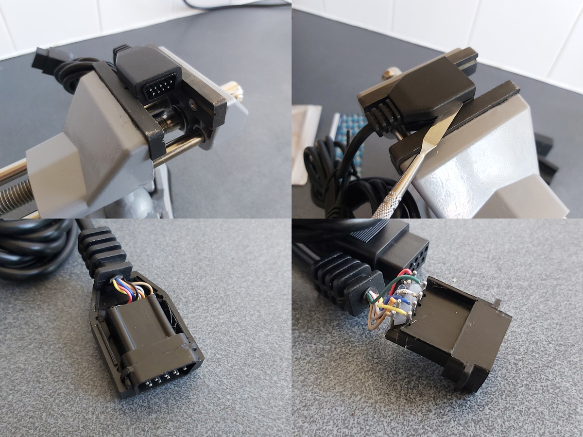
I nearly always put my projects in off-the-shelf enclosures, cutting and drilling holes in them where required. In this project's case the most awkward holes to cut will be for the controller connectors as they do not have an external lip to mask any poorly-cut holes. As such, I thought I'd start here:

My process here is a bit tedious, but gets the job done – I cover the enclosure in masking tape, then mark out where the holes should appear. I use a drill to make several holes inside the shape I wish to cut out, then use a router bit or sharp knife to cut between the holes to open up the hole properly. A set of hand files is then used to bring the hole to its final shape and size, checking against the connector along the way to ensure an accurate fit.
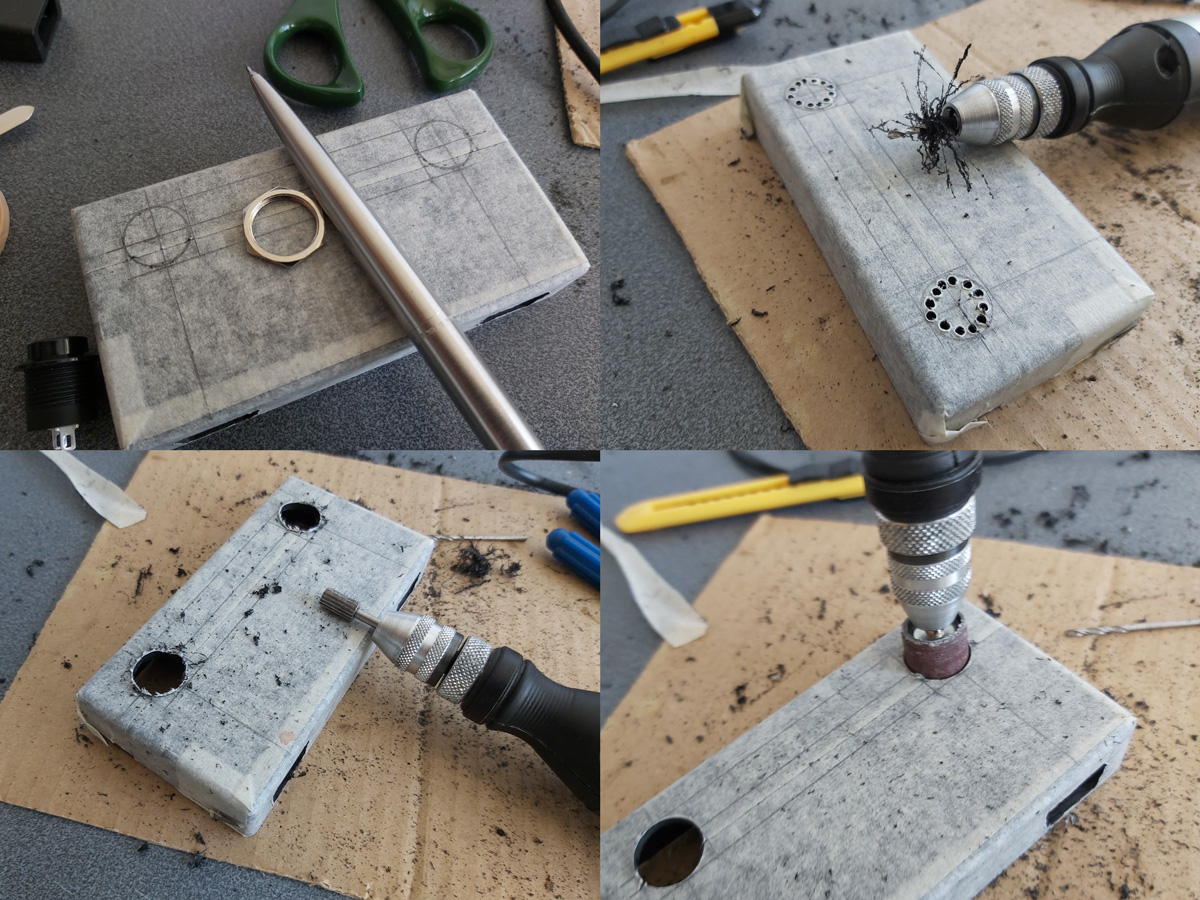
The circular holes for the buttons are cut in a similar fashion, except that as the buttons have outer lips that cover the borders of the hole the outer edges don't need to be quite as precise and a larger router bit and drum sander can speed up the job considerably rather than having to rely on careful hand filing.
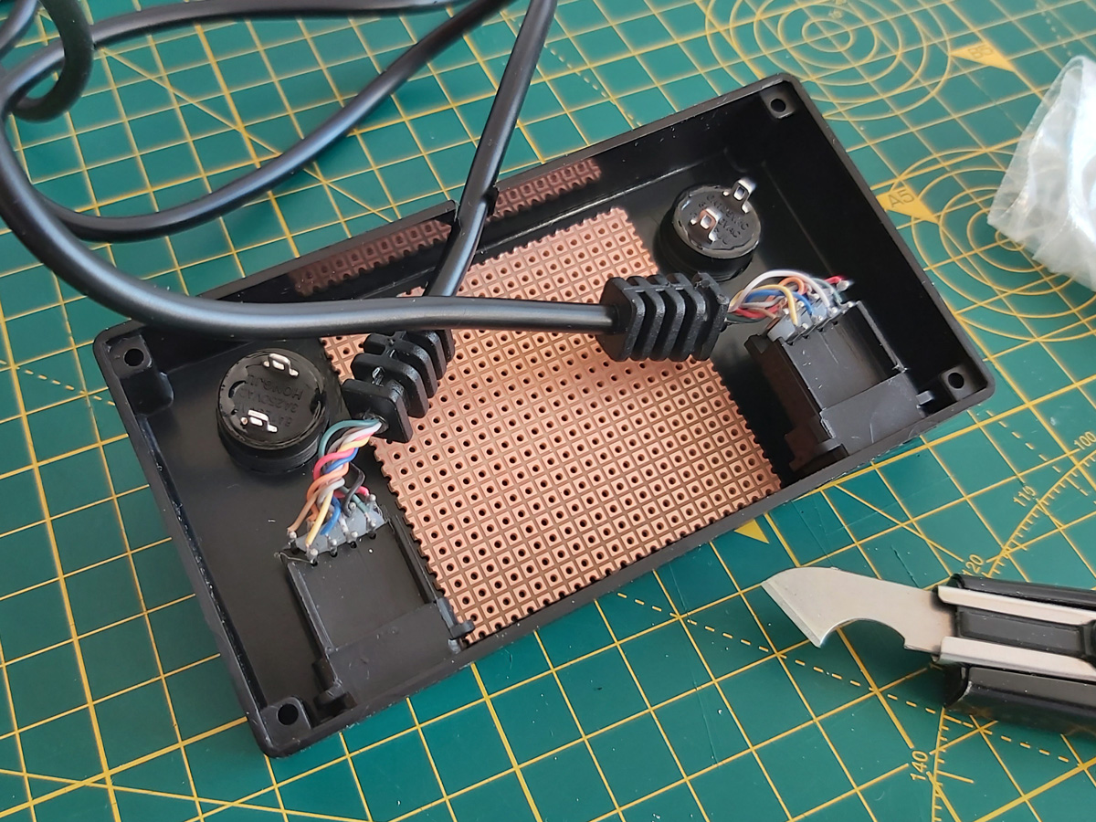
A rectangular notch was cut in the rear centre of the case for the cable to the console to exit through and the parts were then loosely installed for a test fit. A piece of pad board was cut to size by scoring it and snapping it over the edge of a table. I wanted it to be as large as possible to make it easier to fit all of the components and wires in, but could the case be closed with the cables and connectors in place too? To make sure it would I thought I'd start with the bulkiest of cables, the one that goes to the console.
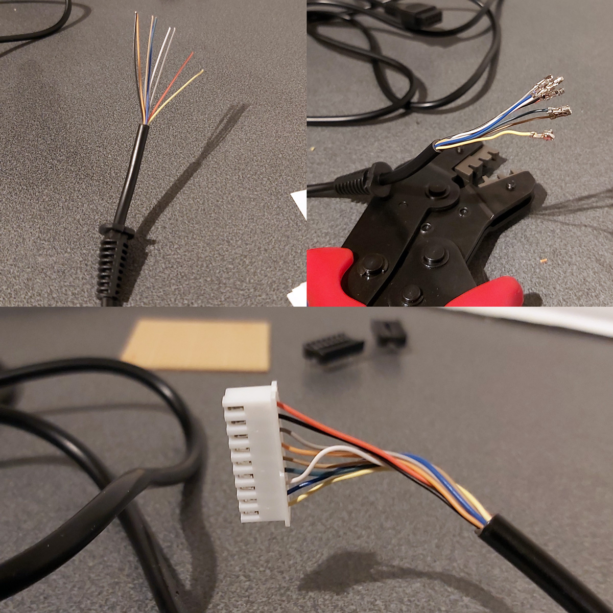
I attached a nine-pin crimp connector to the end of the controller cable to plug into the pad board and experimented with the placement of the destination connector – I found that four rows down was about the closest it could go to the top edge of the board whilst still providing enough room for the cable coming in to bend neatly out of the way.
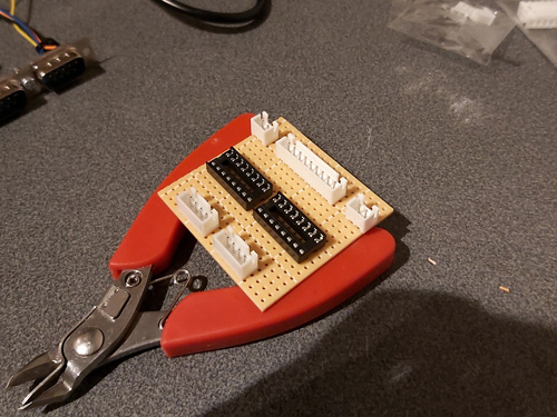
The various parts for the console output connector, light gun input connectors, start button connectors and multiplexer chip DIL sockets were placed on the pad board without soldering to get a rough idea of the final layout and component spacing, ensuring there was enough space around each part to install other components or wires. Once a rough idea was in mind, the main soldering work could begin!
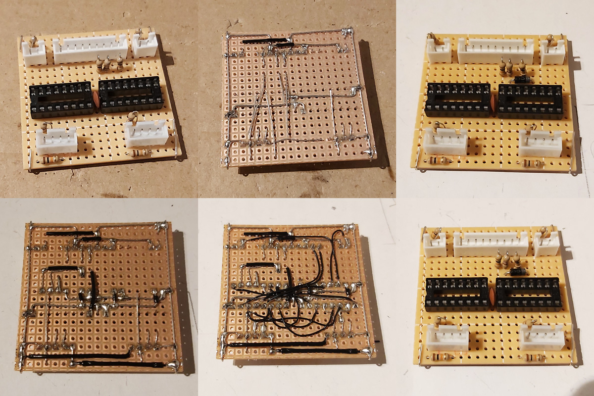
Not much appears to happen between the first and final stages, as most of the work takes place in the wiring on the bottom of the board. Connections that can be made in straight lines without crossing other connections are soldered first, followed by straight connections that cross other connections that can be insulated by slipping on a piece of insulation stripped from a reel of wire. When all of the easy connections are made in this way the outstanding connections are made by soldering lengths of thin wire wrap wire between points on the underside of the board. As each connection is made it is crossed off the circuit diagram – this allows me to check that the circuit diagram is correct, as if I can replicate the circuit from this diagram it's a pretty good indication that it's safe for other people to use to make their own versions of this project.
The DE-9 sockets used for the Light Phaser inputs have all nine pins soldered to the cable by default. We only care about four of them (VCC, GND, TL and TH) and as we don't have enough room for all nine connections to be soldered to the board four-pin connectors are used instead. The old wires are unsoldered and new wires and crimp connectors are attached in their place. This let me check that the circuit board was otherwise working fine, but I still need to figure out how to mount these connectors securely inside the enclosure. I was initially thinking of just holding them in place with hot glue, but this is not very elegant and makes future maintenance much harder! The DE-9 sockets do have a flat surface at the top that is only slightly more than 5mm from the top surface of the enclosure, and I do have some 5mm PCB standoffs that could be handy…
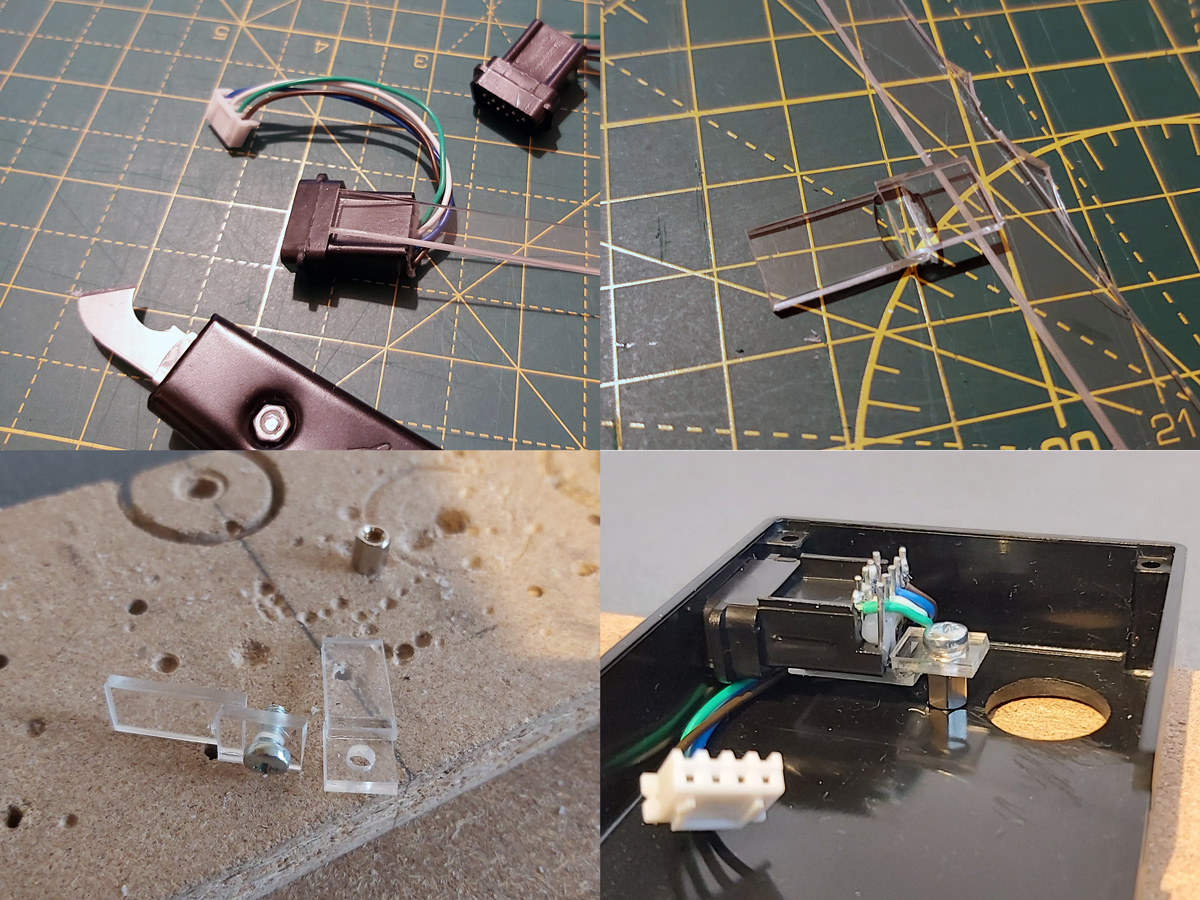
I cut a 9mm wide strip of acrylic from 2mm thick sheet which fits neatly into the top channel of the DE-9 connectors. I then cut it into short sections that could be glued together into Z-shaped brackets. The long section of the "Z" mounts to the DE-9 connector and the short section has a hole drilled through it so it can be secured to the PCB stand-off with a screw. The arrangement is then test fit inside the enclosure using double-sided sticky tape to check that a solid mount is possible – the screw to the PCB stand-off accounts for one part of that mount, and the tight fit of the connector inside the D-shaped hole in the enslosure accounts for the other part.
When it seems like a good fit is possible the Z-shaped brackets are glued to their DE-9 connectors. The DE-9 connectors are then installed in the enclosure with some glue on the bottom of the PCB stand-offs – when everything is lined up neatly this glue secures the stand-offs in the right position, albeit not very strongly.
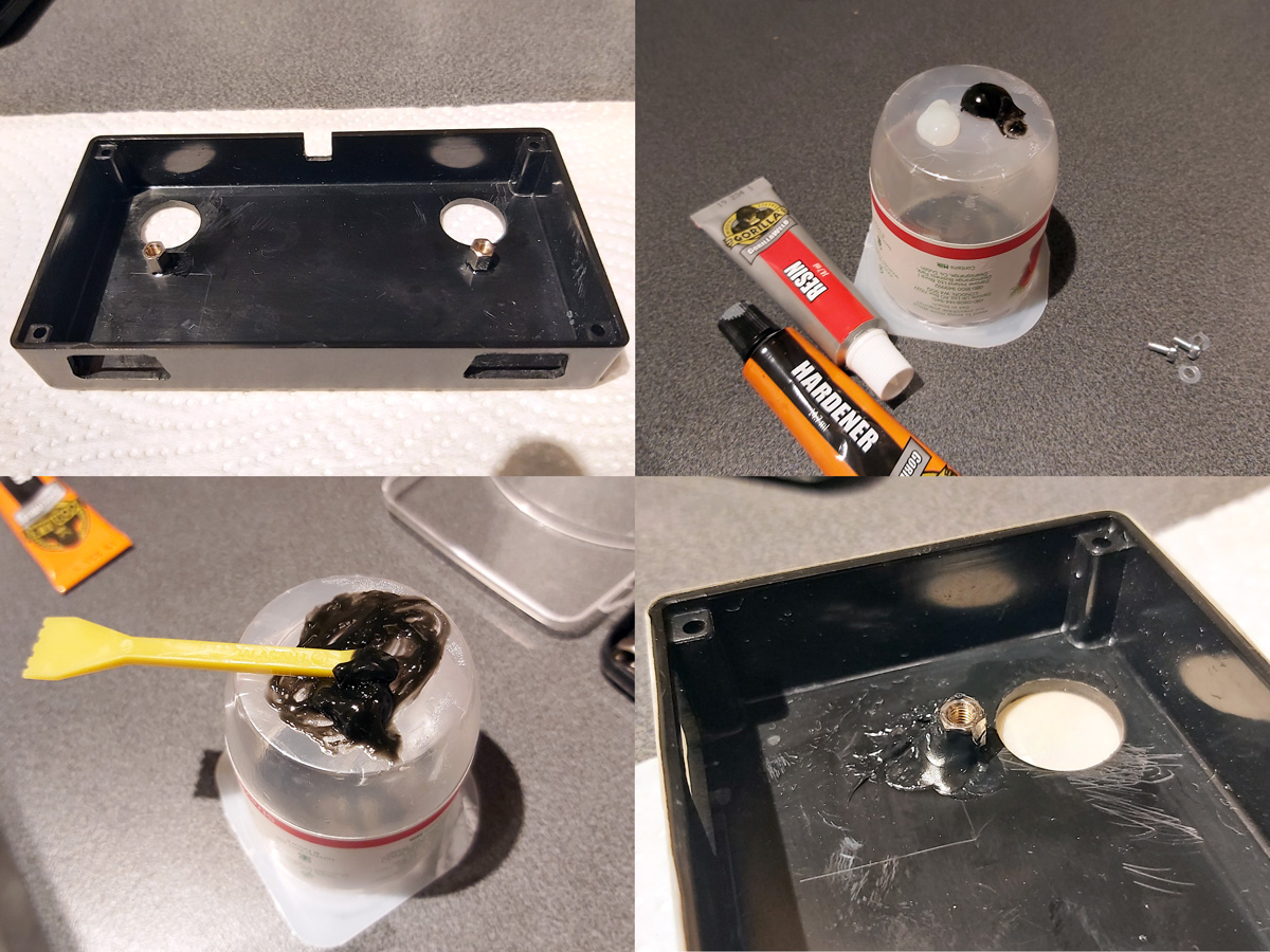
Once the glue had set the screws were removed and the DE-9 sockets were carefully removed. Two-part epoxy was then applied liberally around the PCB stand-offs to provide a bit of extra support. Unfortunately, the stand-offs are very close to the nuts used to secure the start buttons to the enclosure and as such not much epoxy could be placed on that side but hopefully the rest should provide enough support.

Whilst the epoxy was curing the final parts of the project could be assembled – a pair of start buttons had wires soldered to them with crimp connectors on the other end and a couple of rubber strips were cut to provide a bit of extra grip to the bottom of the adaptor. The various component parts of the project can be seen in the photo above.
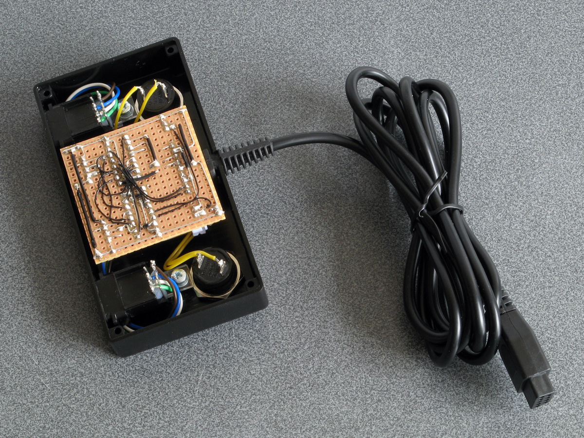
Everything does fit fairly neatly inside the enclosure, fortunately! After everything is assembled inside the bottom of the enclosure was screwed on and the rubber grip strips attached with double-sided sticky tape.
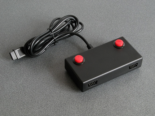
I still haven't been able to test this adaptor with any Mega CD games however it does work well in both Lethal Enforcers and Lethal Enforcers II: Gun Fighters on the stock Mega Drive so hopefully it will also work well in Mega CD games.

I'm pretty happy with how this project turned out. If you would like to assemble the adaptor yourself, you can find the schematic in the previous journal entry, and if you do build it I'd love to hear how you got on!
Adding some protective resistors to the Light Phaser to Mega Drive gun adaptors
Monday, 20th April 2020
Here's a quick update to the two Mega Drive light gun adaptor circuits, all to a few extra resistors in and around the adaptor and the console.
The real Sega Menacer receiver drives the TH line (used to indicate when the gun has seen light) directly from the output of a NOR gate with a 470Ω resistor in series. My circuit uses a transistor in the open-collector configuration with a 10KΩ resistor on the base input and a 1KΩ pull-up resistor, which is the same as the circuit used in the original Sega Light Phaser.
In a worst-case scenario the console could configure TH as an output, drive it high, and the Menacer adaptor could drive TH low at the same time. This would short the console's TH output to ground via the transistor, and might damage it (I'm not sure how these I/O ports are constructed internally). The TH output from a regular Sega Light Phaser would have the same problem, however that only pulses low briefly when it sees the light from the CRT whereas the TH output from the Menacer adaptor is latched and can stay low for a much longer time, increasing the risk. Resistors are cheap, so assuming the engineers at Sega know their hardware better than I do I thought it safer to add a 470Ω resistor on the TH output. This hasn't affected performance, as far as I can see. I also corrected the diagram to reference the BC548 as this is the transistor I tested with – the BC547 probably works too, however in the interest of accuracy I thought it best to stick with what I know works.
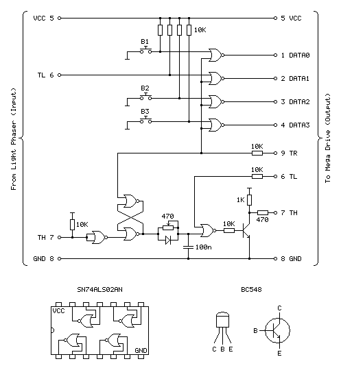
Sega Light Phaser to Sega Menacer adaptor
The Menacer circuit (as well as the original control pad) drives the DATA0~DATA3 lines directly so I haven't included any resistors there. I have, however, applied the same resistor changes to the Justifier adaptor:
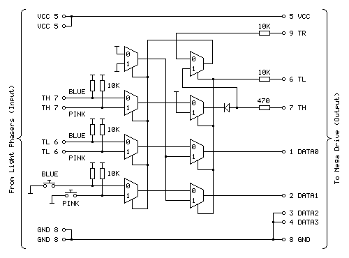
Sega Light Phaser to Konami Justifier adaptor
As well as the 470Ω resistor on the TH input/output line I have added the 10KΩ resistors on the TL and TR input lines. I'm still not sure what these are for but as they are there in the Menacer adaptor and as Sega presumably know best I've included them here for completeness. As these are attached to inputs on the logic gates there should be very high impedance anyway, but it could be for protection in case the logic gates are improperly powered. What I do know is that the extra 10KΩ pull-ups on the TH inputs from the Light Phasers should protect against spurious TH outputs when either of the guns are unplugged.
I still haven't been able to test the circuit with any other games, but for now these two circuits seem to be holding up!
Simplifying the Light Phaser to Justifier adaptor to a two-chip solution
Saturday, 18th April 2020
In the previous post I mentioned I was dissatisfied with the optimisation of the Light Phaser to Justifier adaptor circuit. This was because I was using two quad two-input multiplexer chips (eight multiplexers total) but only using three multiplexers on each chip but also needed two inverter gates and so had to add a third chip to accommodate that requirement. It seemed like there must be a better solution, and after pondering this in the shower I think I found it.
One of the inverters is required for the transistor used to drive the TH line from the circuit. The TH line is bidirectional, and from our end of the circuit is either left floating (where it can rise high) or pulled directly to ground. To achieve this I was using an NPN transistor with the collector connected to TH, the emitter connected to ground and the base connected (via a resistor) to our logic signal. Unfortunately, such a transistor is switched on by a positive voltage and so a logic high at the input resulted in a logic low on TH, so to correct this an inverter was added.
A much simpler solution is to get rid of the inverter and transistor entirely and to replace it with a reverse-biased diode, replacing three components with one:
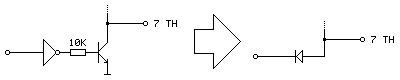
Current can only flow the diode if the voltage at the anode (right, connected to TH) is higher than the voltage at the cathode (left, connected to our logic signal). This means that if our logic signal is the same as the current state as TH then no current flows (and so we leave TH alone) and if our logic signal is high and TH is low then the diode is "backwards" and no current flows. The only way we can influence TH is if it is high and our logic signal is low, allowing current to flow through the diode, grounding TH – which is our desired outcome. One inverter is out of the way!
The other inverter is used to produce an inverted version of TH which is used when the console is retrieving the peripheral ID from the Justifier. We can use a multiplexer as an inverter by using the select pin as the input, tying the "0" input high and the "1" input low (that way when 0 is requested 1 is output and when 1 is requested 0 is output). The problem we have here is that all four multiplexers on a chip share a common selection pin, we need to invert TH, and neither of our two multiplexers is using TH as the select pin (one is using TR to select between the two guns and the other is using TL to globally enable or disable the guns).
The solution here is that we only need this inverted TH signal during the peripheral ID check which is carried out when the guns are globally disabled. When the guns are disabled we don't care about what the TR gun-selection multiplexer is doing, as whether the blue gun or pink gun is selected is irrelevant as the data never makes it to the console. We can therefore use the spare multiplexer on the TL-selected multiplexer chip to select between TR and TH, and use the output of this as the select pin into the multiplexer chip previously used to select between the two guns and use its spare multiplexer as the inverter.
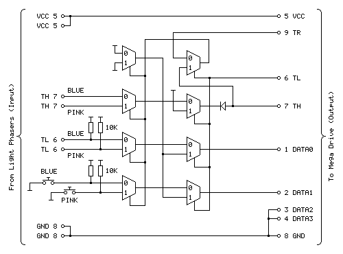
The revised circuit is shown above, the wiring is more complicated than the previous one however it takes advantage of all eight multiplexers on both chips and does away with the need to have an additional inverter logic chip and transistor driver circuit for TH.

The revised two-chip prototype is picture above, and has been tested successfully with Lethal Enforcers – performance doesn't seem to be any different from before, which seems to be a good sign!
Using Master System Light Phasers to play Konami Justifier games on the Mega Drive
Saturday, 18th April 2020
Following my adventures with building an adaptor that lets me use Sega Light Phaser guns in Sega Menacer games it seemed sensible to turn my attention to the other type of light gun for the Sega Mega Drive – the Konami Justifier.

These guns are unsurprisingly incompatible with the Sega Menacer and Sega Light Phaser and supported in even fewer games on the stock Mega Drive (only Lethal Enforcers and Lethal Enforcers II: Gun Fighters). However, these games are more in line with the type of light gun game that I like to play than what you'd find in the Menacer's library (even though the digitised sprites haven't aged particularly gracefully) and the guns are eye-wateringly expensive if you want to get a set of both for two-player games which makes the idea of a cheap adaptor to use the Master System's Light Phaser more appealing. And, of course, it's a fun challenge!
You may have noticed that the two guns in the photo at the top of the post are different colours, and unfortunately this is not purely cosmetic. The Justifier comes in distinct "player 1" and "player 2" variants, with the first gun plugging into the console and the second gun plugging into the bottom of the first gun using a modular connector in a daisy-chain configuration. This allowed Komani to sell console-specific blue player 1 guns and a generic pink player 2 gun that would work with the blue player 1 gun from any system. If you invited a friend over to play with you then you'd need to go out of your way to buy the specific player 2 gun (your friend's blue player 1 gun won't work), and as the blue gun was not sold separately you couldn't buy a game and "upgrade" to a light gun controller later, you'd need to buy one that came with a game and as a result both guns are now somewhat difficult to find and fairly expensive, especially the player 2 gun.
However, this arrangement should allow for a pretty neat solution where we can build a single adaptor that plugs into a controller port on the Mega Drive and provides two controller ports for the two Light Phaser guns rather than having to build two separator adaptors. Like the Menacer, the Justifier does have an extra button when compared to the Light Phaser however it's only one button this time (rather than three) and it's used as a Start button so both of these could be put on the adaptor unit itself between the two players.
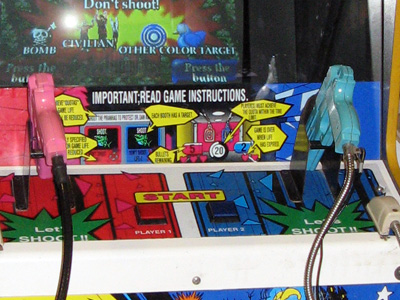
A Point Blank arcade machine with two Start buttons on the control panel between the two guns.
Without buying a pair of Justifier guns, how can it be studied so an adaptor can be built? In the case of the Menacer the receiver units can be bought cheaply and studied to figure out how they interface with the console and the patent document covers how it should work in high-level detail too. I have been unable to find such information for the Justifier. Fortunately Eke-Eke, the author of the Genesis Plus GX emulator, came to the rescue with the document gen_lightgun.pdf which goes into some detail about how the Justifier interfaces with the Mega Drive.
The key information to take into account here is that DATA0 is mapped to the trigger, DATA1 is mapped to the start button, TH is used for the light sensor, TR is used to select which of the two guns to query and TL is used as a general gun enable/disable line. As both guns share the same data lines for their triggers, start buttons and light sensors we can use multiplexers to select between the two guns.
The Mega Drive also needs to be able to detect when the Justifier is plugged in, and it does this by checking the state of the four DATA lines, once when TH is high and once when TH is low, then combining the bit values read in both states to form a single four-bit peripheral ID. The process was explained in more detail in an earlier post, however for the sake of simplicity to correctly return the device ID of %0001 we need to make sure that when TH is high all four data lines are low and when TH is low DATA2 and DATA3 should still be low and one or both of DATA0 and DATA1 should be high.
As DATA2 and DATA3 are always low and aren't used anywhere else they can just be tied low at all times and that should work. DATA0 and DATA1 should pass through the trigger/start button status (active low signals, so normally high) when the game is reading the button state but it looks like they should be forced low when TH is high. According to Eke-Eke's documentation: "I'm not sure why Justifier returns such values, maybe setting TH=1 will force input lines to 0".
My first attempt, therefore, was to use a NOR gate outputting to each of the two data lines with one input to each coming from the TH line and the other input coming from the inverted trigger/start button status. This way if TH was high both data lines would be forced low, otherwise it would output the inverted form of the input (and as the input to the NOR gate was already inverted, the final signal would be corrected – two wrongs do make a right in electronics!) This would not work if both trigger and start button were pressed, unfortunately, but maybe that wouldn't be a problem?
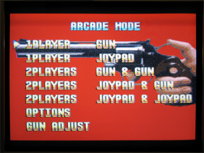
Happily, this worked in the menu for Lethal Enforcers, with the adaptor plugged in I was able to select the option to start a one- or two-player gun game! However, the game was completely unresponsive to the buttons. When writing an emulator you can make certain assumptions about how the hardware works, as long as the right values are in the right places when the software reads them. You also have the advantage of being privy to the internal state of the hardware that external devices might not be able to see! One important note in Eke-Eke's documentation is "this means the Justifier should return the following byte values when TH is set as output" – we can't directly tell whether a pin is set to an output or an input from outside the console, we can only see what its current signal level is. During normal gameplay TH is an active-low signal from the light gun's light sensor, and as a result TH is normally high which blocks the buttons from working. I had thought that maybe the game software would drive the TH pin low during its button-reading routine to allow the data to pass through but evidently the gun doesn't work this way.
Another issue is that whilst I can use a logic analyser to see what state the pins are in over a period of time, I can't tell at what point the console is reading those pins itself and making decisions based on what it sees. I could disassemble the game code to try to see how that's working, but I couldn't figure out any meaningful output from the disassembly tools I tried and couldn't find an appropriate debugging emulator so went back to trial and error.
The solution, I think, is in the TL pin being used to enable or disable the guns. I think that we should only mess around with forcing DATA0 and DATA1 high or low (based on the state of TH) when the guns are disabled, otherwise we let the button and light sensor state pass through. We can achieve this with two stages of multiplexers, one to select between the two guns (selected by TR) and another to globally enable/disable the guns (selected by TL). If we invert TH we can use this to drive the DATA0 and DATA1 lines when the guns are disabled, meaning that we also fix the problem where the gun wouldn't be detected if both buttons were held.
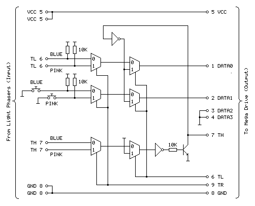
The above diagram shows the circuit I'm currently using to test with and it appears to work fairly well with Lethal Enforcers, being detected as a valid gun during startup and working in-game with both guns seemingly being handled correctly.
The first column of three multiplexers selects between the blue (player 1) and pink (player 2) gun inputs via the TR input. The top multiplexer handles the trigger (TL), the middle multiplexer handles the two Start buttons and the bottom multiplexer handles the light sensor inputs (TH). The second column of three multiplexers selects between the guns being enabled and guns being disabled via the TL input. When the guns are disabled (TL is high) DATA0 and DATA1 are driven by the inverse of TH to help provide the valid %0001 peripheral ID, allowing the adaptor to be detected as a Justifier.
The TH pin is a bit more challenging as it needs to be both an input and an output. At the moment when the guns are disabled it is driven high by tying the other input to the multiplexer high. The TH output is driven by a transistor; when the transistor is switched on it connects TH to ground (making it low) and when it is switched off it is left to float (normally floating high, but otherwise under the control of the console). As the transistor is switched on by a positive voltage this effectively acts as an inverter, hence the signal from the multiplexer to the transistor also needs to be inverted.

The prototype adaptor assembled on a solderless breadboard.
I'm not entirely happy with the way the circuit has been implemented, in particular the use of two multiplexer chips where only three of the four multiplexers are used and the need for an additional chip for the inverter gates. Multiplexer chips normally have a global enable/disable pin in addition to their data selector, which makes me wonder if such a pin could be useful. The 74HCT157 chips I'm using drive the outputs low when disabled which would not be very useful in this particular use case, however other chips are available that make the outputs high-impedence when disabled which may be more useful and allow for a circuit design that uses fewer parts.
There is also a slight issue of reliability and accuracy. When playing the game shots are generally fairly accurate and always register however they sometimes are offset horizontally. Eke-Eke's document points out that Lethal Enforcers does not use the console's horizontal counter latch so the inaccuracy may be a software issue – interestingly it seems Lethal Enforcers II does use the horizontal counter latch so when I can test with this cartridge it will be interesting to see whether accuracy is affected. More weirdly, the game does provide a "gun adjust" menu option where you can calibrate the game to compensate for any horizontal or vertical offset in the gun hardware however this does not seem to detect all shots and sometimes the accuracy is miles out! This also seems to be affected quite heavily by proximity to the screen, normally bringing the gun closer to the screen yields more accurate results however here it seems to make things worse. I'm not sure why this is and will continue to test the circuit to see if performance can be improved.
The completed Light Phaser to Menacer adaptor
Friday, 10th April 2020
In the last post I was having difficulty with the overall logic for handling the light sensor signal from the Sega Light Phaser and passing that along to the Mega Drive as if it was coming from the Menacer receiver. This involves latching the signal (instead of passing it along directly) and allowing the console to reset it once handled via the TR line. The signal needs to be delayed as well to simulate the delay from the overhead of the Menacer's wireless communications; without this delay the aiming is offset to the left. The signal is also gated using the TL line; I'm not entirely sure why this is done (some form of external interrupt inhibition?) but it's part of the original receiver so I thought it best to implement this for the sake of compatibility.
My main problem was that the CMOS NOR chip I had to hand was not triggering reliably with the signal from the light gun and the RC circuit used to delay that signal; I'd swapped it for a TTL NAND chip which then did work however the logic inputs to the latch were inverted (a simple NOR latch has active-high inputs and a simple NAND latch has active-low inputs) and to fix this would have required a lot of additional logic gates. I ordered an SN74ALS02AN TTL NOR chip and found that this worked very well, so have settled on the following circuit:
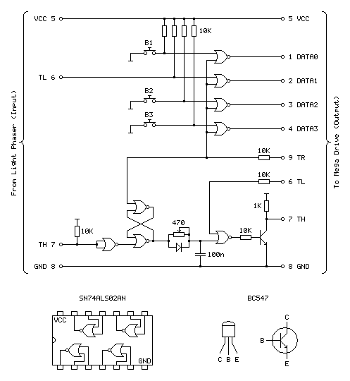
Update (20/04/2020): Please see this post for an updated diagram with a protective 470Ω resistor on the TH output
The four NOR gates towards the top of the circuit diagram are used to gate and invert the inputs from the four input buttons (one main trigger on the Light Phaser and three secondary function buttons on the adaptor itself). This is unchanged from the previous circuit and still works well.
The most important aspect of the circuit at the bottom of the diagram between the two TH pins is the latch made of two crossed-over NOR gates with the output from one going to the input of the other and vice-versa. The two inputs to this latch are normally low (TR from the console is driven directly and normally low, TH from the Light Phaser is normally high but inverted by a NOR gate with its legs tied together). When the reset pin TR goes high the output of the top gate must go low, as a NOR gate will always output low if either (or both) of its inputs are high:
| Inputs | Output | |
|---|---|---|
| A | B | Q = A+B |
| 0 | 0 | 1 |
| 0 | 1 | 0 |
| 1 | 0 | 0 |
| 1 | 1 | 0 |
If we assume that the other input to the lower NOR gate is also in its default low state then the two low inputs will result in a high output. This high input travels back to the top NOR gate's other input. This means that even when the TR pin goes back low again there is still a high input on that top NOR gate and so it maintains its low output.
When the Light Phaser sees light its TH output goes low, the NOR gate with its legs tied together inverts this to go high and the bottom input to the lower NOR gate in the latch goes high. This makes its output go low, which travels to the top NOR gate, making both inputs low (assuming TR is still low) and making the top NOR gate output a high which comes back down to the lower NOR gate so that even when the Light Phaser stops seeing light and the other input to the bottom NOR goes back to low there is still a high on the other pin, keeping the overall output low.
Effectively, what this means is that when the Light Phaser sees light the output of the latch goes low, and to return this back to a high the console needs to pulse the TR pin high.
The output of the latch goes to a delay circuit consisting of a resistor, capacitor and diode. This delay is required because the real Menacer introduces a delay between when it sees light and when it triggers the console's TH pin, and games are programmed to compensate for this. Without replicating this delay the aim is offset considerably to the left.
The logic gates are digital devices however still adhere to analogue rules and will treat certain voltages as high or low digital signals when they pass a certain threshold. The delay is implemented by slowing the rise or fall of the logic signal by charging a capacitor via a resistor, so whilst the logic signal at the output of the latch changes very quickly it will take the capacitor a while to charge or discharge via that resistor to a voltage level that is interpreted as a change of state by the following logic gate. The diode is there because we want the signal to be delayed when the gun sees light (when the logic level goes from high to low) but want it to change quickly when the latch is reset (going from low back to high again). When going from low to high there is a higher voltage to the left of the diode than there is across the capacitor to its right and so current can flow quickly through the diode, bypassing the slow resistor and charging up the capacitor quickly. When going from high to low the current can't flow backwards through the diode and so the capacitor has to discharge slowly through the resistor, providing the desired delay.
After this delay comes another NOR gate with its other input coming from the console's TL pin. I'm not entirely sure what this is for, as mentioned above, but it does at least allow us to buffer the signal from the RC delay circuit. The real receiver circuit then uses a final NOR gate with its inputs tied together to invert the latched signal before passing it to the console via a 470Ω resistor, but as I am already using an extra NOR gate to invert the input from the Light Phaser and have therefore used all four gates on one chip I instead use a transistor with a 1K pullup to invert the signal. The Light Phaser uses such a transistor circuit with the same 1K pullup resistor on its TH output so I thought it safe to use it here as it would be electrically compatible. The real receiver also includes 10K series resistors on its inputs from the TR and TL lines – I'm not entirely sure why but in case there was a good reason I thought I should use them here also!
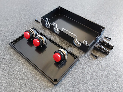
With the circuit appearing to work well I thought it was time to put it in an enclosure. I found a box that was a comfortable size to hold in one hand – it's about the same overall size of a Master System control pad other than being quite a bit fatter. This allowed me to put the three push buttons down the side of the box so they can all be pressed easily when gripping the box in one hand. The lid of the box has a lip that would interefere with the ability to tighten the nuts for the buttons and so I cut a small piece of acrylic that is slightly thicker than the lip and short enough that the box can be closed with it in place.
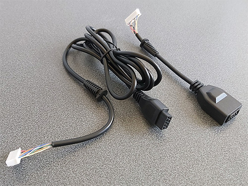
Of course, we need something to plug the Light Phaser into and a cable to plug the adaptor into the console with. A good source for these connectors is an inexpensive extension cable, so I bought one and cut it in two so I could use it for this project. After cutting the cable in two I installed strain reliefs and crimp connectors, and definitely remember to do that in that order! Interestingly I've bought a few of these cables recently from different suppliers (and with different moulding designs for the console plug and controller socket) and they've always been about half the length advertised but sold in packs of two.
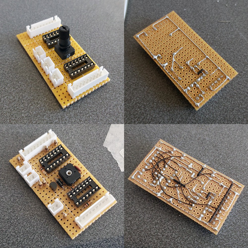
I normally use pad board to solder my final circuits together. I start by roughly placing the components on the board where I think they should end up going, and when I've got the main parts in place I flip the board over and start soldering them down, using bare pieces of wire to make connections between components. I lay the bare pieces of wire as straight as possible and try to avoid crossing them over; where necessary I'll add a piece of insulation to a wire where it needs to cross another. Once as much of the board is placed in that fashion I'll solder thin wires between the points that can't have direct connections. It may not be the prettiest job (and making corrections afterwards is a bit of a pain) but it's worked well for me and I've found it allows for more compact layouts than stripboard.
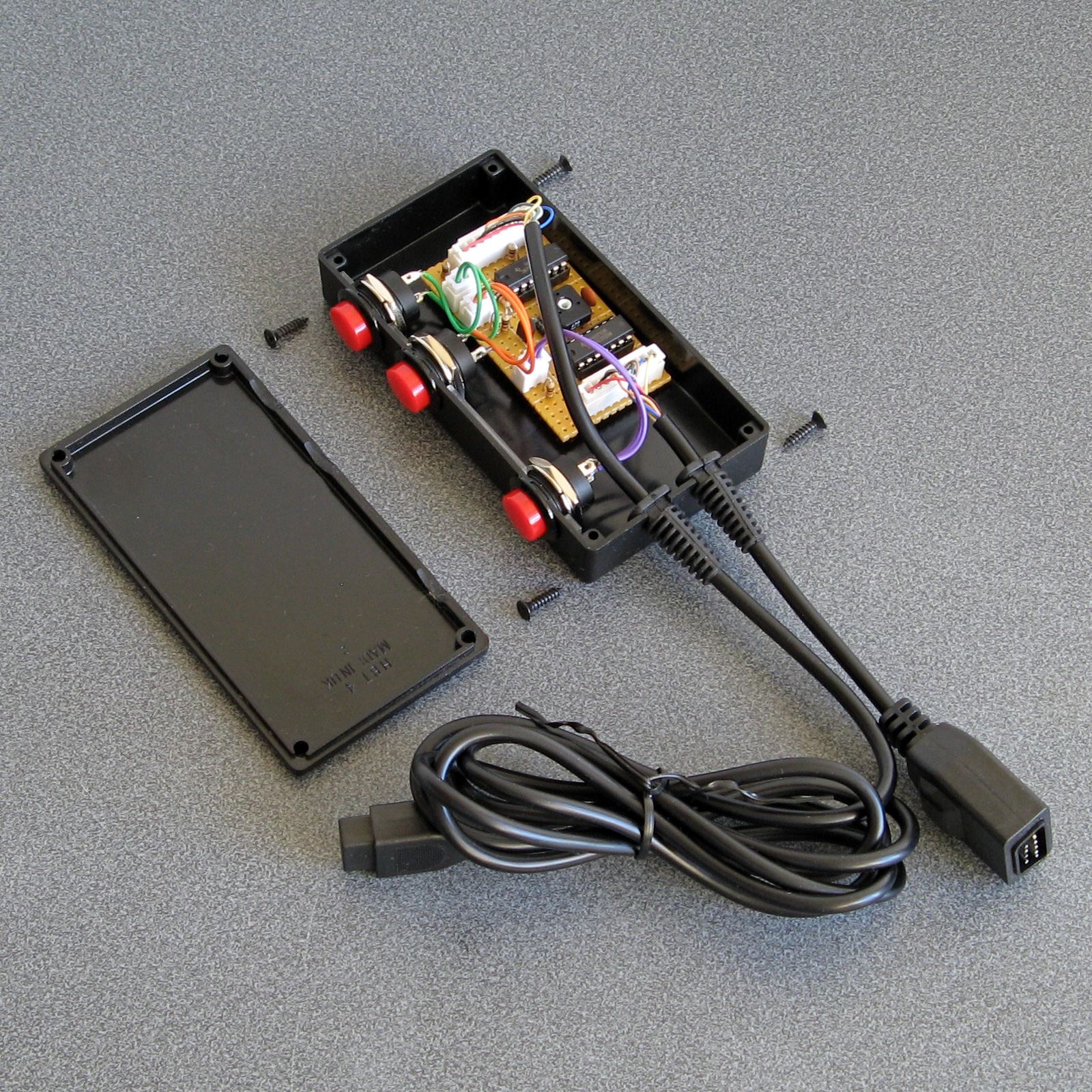
Some crimp connectors were then added to the three push buttons and the whole circuit was installed in the box. Before the lid was screwed down the delay to correct the horizontal aim was calibrated using the 470Ω variable resistor. To adjust it the variable resistor was first set to its smallest resistance value and the tip of the light gun was touched to the centre of the screen. The aiming reticle is quite far to the left by default so the resistance of the variable resistor was then gradually increased to move the aiming reticle in the game right until it sits under the tip of the gun. The aim was then checked at the extreme left and right sides of the screen and if there were any dead zones the variable resistor was adjusted to move the aiming reticle away from the edge of the screen until it had a good range of motion across the entire width of the screen.
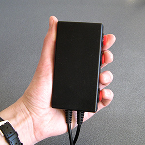
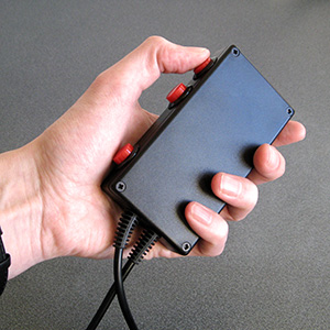
The two different grip styles for the adaptor buttons
The adaptor can be gripped in two different ways – in the regular position you have direct access to all three extra buttons with your fingers, and in the reversed position you have access to a single button at a time with your thumb. None of the games I've played on the Mega Drive use more than two extra buttons (and usually one of those is the bottom "Pause" button) but it's always good to have options!
I have tested the adaptor with the three Mega Drive games that support the Menacer — the six-in-one pack-in cartridge, T2: The Arcade Game and Body Count and am happy to report that it works with all three. I am not going to be able to test it with any Mega CD games as I do not have a Mega CD or a compatible flash cartridge, I'm afraid to say, but hopefully it will work just as well with those games.

The red and black theme was chosen to match the other accessories and I think it fits in rather well, even if it is a bit boxy-looking. If you are reading this and build the circuit yourself I'd love to hear how you get on!
Fixing the Menacer detection but breaking the accuracy of the aim tracking
Thursday, 26th March 2020
Since the last post about my experiments with using a Sega Light Phaser to play Mega Drive games I've had some good results and some disappointing ones that I'm still trying to work through.
The easy problem to solve was the handling of the buttons and making sure that the gun continued to be detected as a Menacer whenever a button was pressed. The previous circuit used active-high buttons (including an inverter to convert the active-low trigger from the Light Phaser into active-high signal) gated using the console's TH line via an AND gate. This meant that each button output a 0 when not pressed and 1 when pressed when TH was high, or a 0 in all cases whether TH was low or high.
When looking at the patent for the Menacer it became apparent that the button data lines were coming from a four-bit counter that is reset by the console's TR pin going high. When looking at logic analyser traces from T2: The Arcade Game we can see that TR is held high during device detection at the main menu screen but goes low during gameplay, being periodically pulsed high when the game alternates between handling light detection (short pulse) and reading button presses (long pulse). Rather than active-high buttons with AND gates, active-low buttons with NOR gates would seem to work better, so I ordered some NOR gate chips and tried the following circuit:
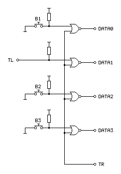
In the diagram above the TL on the left comes from the Light Phaser and the connections on the right go to the Mega Drive.
An OR gate will output a 1 if either of its inputs is a 1, to output a 0 both inputs have to be 0. A NOR gate inverts this output, so will output a 0 if either of the inputs is a 1 and will only output a 1 if both inputs are 0. When TR from the console is 1 it therefore forces the output to always be a 0, however if TR goes low to a 0 then the output is 0 if a button is released and 1 if a button is pressed – just what we needed.
Testing with T2: The Arcade Game I found that all of the buttons still worked during gameplay, and when pressing a button at the main menu the gun continued to be detected as a Menacer unlike the previous buggy implementation. All good so far!
I wanted to test with some other games, so ended up buying a copy of the six game cartridge that was originally bundled with the Menacer. I paid a little bit more and got a copy that came with the IR receiver, which is not much use without the gun however I thought it still might provider some interesting clues as to how to convert the signals from the Light Phaser to the Menacer protocol more correctly.
When the cartridge arrived I plopped it into my Mega Drive and was happy to see that the games mostly worked fine without any further tweaking. There was one fly in the ointment, however, an occasional message about the screen being too dark:
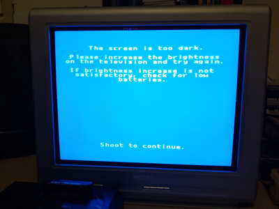
"The screen is too dark".
It would only do this occasionally when launching one of the six games and would then reset to the main intro and menu screen after shooting. Oddly, once a game was started I could quite happily move away from the TV to the other side of the room and the gun still worked reliably, so I'm not sure if this genuinely is an issue with the screen being too dark or if it's some problem with the way the gun is triggering the TH line on the console to indicate when it's seen light.
To try to get to the bottom of the issue I took apart the Menacer receiver and started sketching a circuit diagram based on the counter and NOR gate chips on the board. I then compared my scribbles to the circuit diagram in the patent, and found that the final implementation does appear to match the diagram in the patent pretty much exactly (I can't tell for certain as quite a lot of the circuitry is enclosed in a metal can, but all of the circuitry relating to the counter and NOR gate latch matches). This meant I was able to match up the console's pin connections to the diagram, which are unlabelled in the patent:
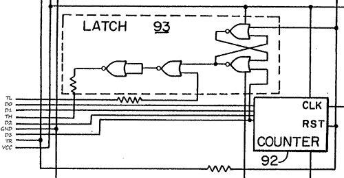
Pin connections for the Menacer receiver
It's not particularly clear due to how closely-packed the connections are in the diagram, however the important details are as follows:
- D0~D3 are connected to the counter directly, with D3 also going to set the latch at the top.
- TR resets the counter and the latch.
- TL appears to inhibit the output of the latch.
- TH only needs a 470Ω resistor between the output of the latch and the input to the console, not a common-emitter transistor driver.
I thought it would be neat if I could combine the function of the latch and the counter, so purchased a CD4017B decade counter chip as this has a handy clock inhibition input and wired it up as follows:
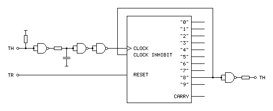
The clock input to this circuit comes from the TH output of the Light Phaser gun. This is an active-low signal so it needs to be inverted to properly clock the counter chip on the rising edge of the signal. It also needs to be delayed slightly for proper horizontal aiming (described in the previous post) so hence the additional RC circuit before the signal is fed to the counter chip.
With such a decade counter one of the 10 outputs labelled "0" to "9" is active at a time. After resetting the chip (by pulsing the reset pin high) "0" is high and "1" to "9" are low. When there is a rising edge at the clock input the chip counts up, so "0" goes low and "1" goes high, then "1" goes low and "2" goes high and so on and so forth. The "carry" output provides a rising edge clock signal when the counter overflows from "9" back to "0", allowing multiple chips to be chained together.
In the Menacer receiver the counter triggers the TH output latch on the fourth bit of a binary counter, i.e. when it reaches 8, so I've used the output of "8" as the output of the circuit. I've also fed this output back to the "clock inhibit" input of the counter chip. When this pin is low (which "8" will be when the counter is reset) it allows the counter to count up normally whenever the clock pin is pulsed. When the pin goes high (which "8" will be when we've seen eight pulses of light from the gun) it will inhibit the counter from counting any further, effectively locking it at "8". The only way out of this condition is to reset the chip, which the console does by pulsing the TR input line.
The only additional complication is that the console still expects an active low signal from the gun, so the final step is to invert the output from the counter.
Unfortunately, this does not work at all well. Games no longer seem to produce the "The screen is too dark" message, however aiming is extremely laggy and inaccurate. Checking the output of the counter with a logic probe seems to indicate erratic triggering. Using a different output from the counter (e.g. "4" or even "1") so that the counter "latches" sooner seems to improve things slightly but overall performance is still far worse in this arrangement. I'm not entirely sure why!
My next attempt was to simplify matters by using the exact latch circuit composed of NOR gates described in the patent, which worked just about as badly – the circuit still triggered eratically and accuracy was very poor. I have had issues with circuits not triggering properly before when using particular logic chips (it's why the circuit for my LCD Shutter Glasses adaptor has SN74LS14N Schmitt-trigger invertors on the logic inputs) so I thought I'd try replacing the CD4001B CMOS NOR gate chip I was using with the SN74ALS00AN TTL NAND gate chip I was using in previous experiments. The logic for a latch built from NAND gates is inverted to the logic of one built from NOR gates so it wasn't a straight swap but I don't have any other NOR gates in my parts bin. Somewhat surprisingly, with this new chip performance was greatly improved, though still not quite right.
For my next set of experiments I'm going to try replacing the CMOS NOR gate with the TTL NOR equivalent, though as that will involve waiting for parts to turn up in the post I thought I'd write a quick update on where I am so far. Fingers crossed this issue can be resolved easily and with a simple circuit!
Using a Master System Light Phaser in Mega Drive Menacer games
Wednesday, 18th March 2020
I'm a big fan of light gun games and have guns and games for most of the Sega systems – the Master System's Light Phaser, the Saturn's Virtua Gun and the Dreamcast's gun all get plenty of use.
One notable omission is the Sega Mega Drive and its Menacer light gun. This is a wireless gun with a range of bulky plastic accoutrements that represented Sega's efforts in the 16-bit generation; unfortunately only three games were released for it on the Mega Drive – a six-in-one collection of minigames that came bundled with the gun, a port of T2: The Arcade Game and the ferociously-expensive Body Count.
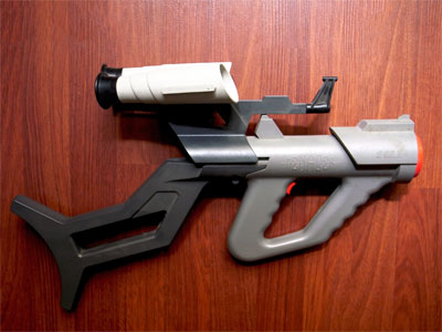
Ultimately the gun was a flop and they are not cheap to pick up second-hand (and are often missing most of the bits) so I haven't sought one out, however I did recently buy a cheap job lot of games which included a loose copy of T2: The Arcade Game.
I tried the game with the regular control pad and found it a disappointing experience (as most light games are when played with a pad!) so thought I'd see if I could get it to work with one of my Master System Light Phaser guns.
Of course, the game wouldn't detect that the gun was plugged in. Controllers on the Master System were generally very simple affairs, with one pin on the controller port per button (no multiplexing or serial data transfers here). On the regular control pad four data lines were used for the d-pad directions and two data lines (TL and TR) were used for the two buttons. These data lines were pulled high by the console and the control pad just contained switches that connected these data lines to ground when pressed for simple active-low logic.
The Light Phaser doesn't make use of the four d-pad data lines and only has one button so only uses one of those two data lines (TL) however it does make use of another pin on the controller (TH) for its light sensor. When this pin goes low the console latches the video chip's horizontal counter and the game software can read this and the free-running vertical counter to determine what point on the screen the console was outputting at the point the gun "saw" the light from the TV (and from this work out where the gun is aiming).
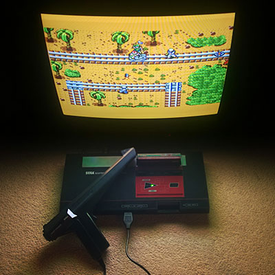
The Sega Light Phaser being used to play Rescue Mission on the Master System.
The Mega Drive is descended from the Master System's design and has very similar controller ports. The d-pad's four data lines are named DATA0 to DATA3, and by default the B and C buttons are mapped to the two TL and TR inputs like the two buttons on the Master System controller. However, the Mega Drive controller adds two extra buttons (A and Start). These two extra buttons share the TL and TR data lines and whether they are B and C or A and Start depends on the state of the TH line which is configured as an output from the console.
This use of the TH line to choose which buttons are mapped to which data lines is also used for controller identification. When TH is high the d-pad is mapped to the four data bits as normal. However, with a normal controller, when TH goes low data lines 2 and 3 (corresponding to left and right) go low also. This is normally impossible, as you can't physically press left and right simultaneously on a Master System controller, so a controller that ignores the state of the TH line won't be detected as a Mega Drive controller.
The device ID is encoded as a four-bit value according to the following logic:
| ID bit | TH state | Data bits |
|---|---|---|
| 3 | High | 3 OR 2 |
| 2 | High | 1 OR 0 |
| 1 | Low | 3 OR 2 |
| 0 | Low | 1 OR 0 |
For example, to read a regular controller's ID set TH to high and read the data lines. In this state the d-pad is mapped to the data lines. Bits 3 and 2 are mapped to to right and left. If neither is pressed both bits will be "1" as the inputs are active-low; 1 OR 1 is 1. If either left or right is pressed then one of the bits will be "0" but the other will be "1"; 0 OR 1 is also 1. The only way to get a zero is if both directions are pressed simultaneously which is not possible, so ID bit 3 will always be 1.
The same applies to ID bit 2, as this is uses data lines 1 and 0 which are mapped to the down and up buttons, so this will also always be a 1.
After setting TH low, we know that data lines 3 and 2 are forced to 0 so ID bit 1 is a 0.
Finally, ID bit 0 is based on data lines 1 and 0 which are still mapped to down and up and so will still be a 1. This all gives us a device ID of %1101, which is indeed the peripheral ID of a standard Mega Drive controller.
This is fine, but what does it mean for the Menacer? Well, that device has an ID of %0000. For this to happen we need to make sure that all four data lines are low whenever the console is reading the device ID. The easy way to do this is to take apart a Master System controller and to press all four d-pad buttons down simultaneously – doing so and starting the console with the T2 cartridge inserted makes the game think that a Menacer is plugged in!
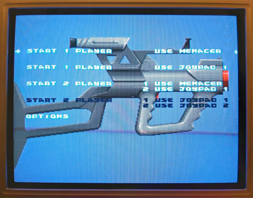
The Use Menacer options are white and selectable.
Somewhat unusually the Menacer's four buttons are mapped to the four data lines (instead of TL/TR) and are active high which means that if I start the game and let go of one of the Master System controller's buttons then it thinks I've pressed one of the Menacer's buttons (for example, releasing the "down" button makes DATA1 go high and the game thinks I'm pulling the trigger). Of course, I can't aim in this mode as there's no light gun input but it's good to see something is working!
I assumed that if TH is normally used for device identification I would start experimenting with using that to determine when the adaptor should output all zeroes. Considering the buttons need to be inverted to active-high logic too I thought it best to use an AND gate on each button so that if TH is high (normal state) the button input would pass through to the data line, but if TH is low (detection state) the data line would be forced low. I wired this up with an AND gate and four push buttons and the game still detected a Menacer and pressing a button in-game would now fire the weapon. Seeing that this worked, I removed one of the four push buttons that was previously used for the trigger button and used the TL data line from the Light Phaser instead via an inverter:
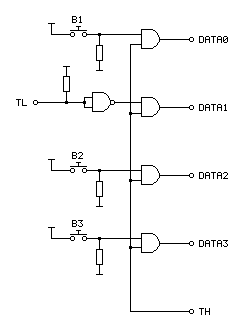
In the diagram above the TL on the left comes from the Light Phaser and the connections on the right go to the Mega Drive.
I assumed that the Menacer would also use the console's TH input for the light sensor from the gun (similar to the Light Phaser) so tried wiring up the Light Phaser's TH output to the Mega Drive's TH input. Moving the gun around the screen moved the aiming cursor around. Unfortunately, the aim was pretty far off:
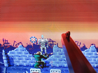
The blue cursor should be under the gun, which is touching the screen.
The game placed the aiming cursor a consistent distance left of where the gun really was aiming. I assumed this was due to the game expecting a delay between when the gun saw the light from the screen and it sending a pulse to the console – unlike a wired gun that can send the signal back to the console very quickly the wireless Menacer converts the detected light pulse into an IR pulse that then needs to be handled by the receiving unit plugged into the console. By the time the console sees this pulse it will have moved further along the current scanline (right), so the game software works backwards (left) to an earlier point on the scanline. As I'm using a wired gun that transmits the signal much more quickly this left offset causes the aim to be incorrect.
The solution to this is to introduce our own delay into the signal, which I did with a crude RC circuit:
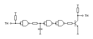
As I'd previously used a NAND chip to invert the signal from the trigger button I used three more of its gates to implement the delay. The first gate buffers the signal as the gun's TH is a common emitter output, so either connected to ground or pulled high via a resistor. This buffered signal then charges or discharges a capacitor to ground via a resistor – this provides most of the delay, and in my testing a 220Ω resistor and 100nF capacitor provided better aim. The next two gates buffer the signal again before driving a transistor for a common emitter output – as the console is also driving the TH line as an output I didn't want to directly drive it from the adaptor circuit and so the transistor seemed safer and is how the Light Phaser works anyway.
This is a crude circuit and has its limitations (very short pulses could be dropped entirely rather than delayed, for example) but it does at least seem to greatly improve the aim:

The cursor now lines up with the point on the screen the gun is touching.
The game is now fairly playable, though there is one notable flaw with the circuit: pressing any button at the main menu screen causes the game to assume the gun has been disconnected, disabling the Menacer options:
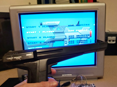
The Use Menacer options are dark and no longer selectable.
Clearly using the TH signal alone to disable the buttons is insufficient, we must need to also output 0 when TH is high for full compatibility with the peripheral ID reading and the gun must use some other technique to enable or disable the button data.
Fortunately, a copy of the Menacer patent can be downloaded from the Sega Retro website where it can be studied to see if it provides any more clues for how the Menacer works. It goes into some detail about how the gun communicates with the console, including this figure showing the gun:
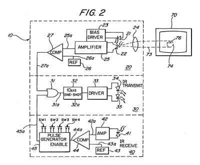
The centre portion of the image shows that infra-red signals from the gun are transmitted to the receiver in the form of 10µs pulses. The top portion of the image shows that these pulses can be generated by the gun's light sensor, so whenever the gun sees light it will send a 10µs IR pulse to the receiver. The bottom portion of the image shows the pulse generator used to encode the button presses; the button state is interpreted as a binary number and a corresponding number of IR pulses are sent: if SW1 is pressed then 1 pulse is sent, if SW2 is pressed then 2 pulses are sent, if SW3 is pressed then 4 pulses are sent and if SW4 is pressed then 8 pulses are sent. If multiple buttons are pressed then their values are added, so if SW1 (1) and SW3 (4) were pressed then five pulses would be sent up to a maximum of 15 pulses for all four buttons being pressed.
These button press pulses are only sent back to the console receiver after the gun receives an IR pulse from the receiver.
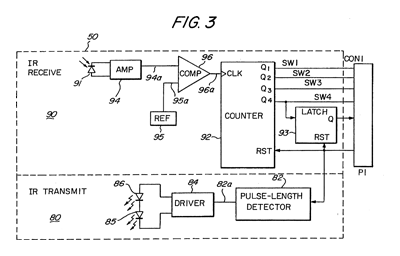
The receiver uses a counter chip to convert the IR pulses from the gun into button press or detected light pulses for the console. The duration of reset pulses are important here. The patent describes a standard counter reset pulse as being 2-3µs long and a main reset signal pulse as being about 10µs long. Any short reset pulse will reset the counter chip and latch. A long reset pulse will stil reset them, but also trigger a pulse of IR via the transmitter section at the bottom of the diagram. This IR pulse will cause the gun to send its button data back to the receiver, where the pulses will be counted by the counter chip and drive the DATA0 to DATA3 pins. After a certain delay to ensure that all button states have been sent the game software can read the button state and reset the counter, ready to read pulses from the light sensor in the gun. Bear in mind that the button state will have to be read before the active display starts, as the gun always sends an IR pulse when it sees light and this will cause the button presses to be miscounted.
Rather than pass every single detected pulse of light from the gun to the console it looks like the counter is used to detect eight pulses, after which it triggers a latch. This appears to be due to the assumption that when the gun is an expected distance away from the TV it will trigger on around 20 scanlines, and so by waiting for eight it will place the detected position roughly in the middle of those 20 lines.
All in all, this is a simple enough system but what does it mean for our convertor circuit? Will we need to add extra pulse length detectors and counters to make sure we send through the right sort of data?
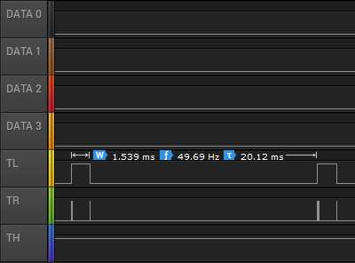
I captured the state of the controller port lines during gameplay and found the above logic traces. Each frame TL goes high briefly and is then low for the active part of the frame. Pin TR has very brief pulses, and these appear to be the reset pulses. If we zoom in, we can see these more clearly:
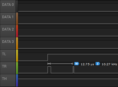
Here TR goes high for over 10µs and so must be the main reset pulse (used to read the button state) and the next pulse is around 3µs and so must be the regular counter reset pulse. The gap between these pulses is only 85µs, however – if the button IR pulses are 10µs long then this would not give us enough time to read them – even if there was no gap between them 15 pulses of 10µs would take 150µs. Either there is a delay of at least 85µs before the gun starts sending the button data or the timing is different in the real gun when compared to the patent information. There is a final 3µs reset pulse as TL falls and this pulse comes 1.435ms after the previous short reset pulse so that would provide plenty of time to receive the button press data before resetting the counter ready to detect light pulses.
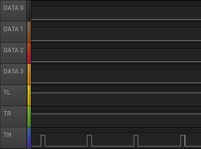
The next bit of the puzzle is what happens during the main menu when the Menacer is being detected. The traces are shown above. Both TL and TR are fixed high during this process. If we assume TR alone is used to reset the counters then holding this high would fix the data lines at %0000, identifying the controller as a Menacer. The TH line is also being pulsed here, possibly as the code is still checking to see if it could be some other type of controller.
If we force the output of the data lines to be 0 when TR is high (acting as a reset) then maybe this would work more reliably (and correctly) than when TH is low. I'll need to perform some further experiments, and also see whether the lack of the eight scanline delay before triggering the TH line to indicate detected light causes any other problems. I like the idea of a simple device that only uses logic chips to adapt the gun but if we need a more sophisticated circuit to time reset pulses and offset the vertical position maybe it would be better to switch to a microcontroller circuit. If that was the case, maybe the adaptor could also be programmed to work with games that use the Konami Justifier, another Mega Drive light gun that is incompatible with the Menacer.
If you'd like to see the circuit in action, I've uploaded a quick video on YouTube to accompany this post.
Modifying a Master System cartridge for use with flash ROMs
Thursday, 22nd August 2019
I have a ToToTEK GG-PRO flash cartridge to run homebrew software on my Game Gear however I have never been able to get it to work on my current PC and it seems that it's hard to find a Master System equivalent these days. A contemporary alternative is the Master EverDrive and it is by all accounts an excellent piece of equipment however it is a very expensive product.
I had, however, heard that certain Master System cartridges could be modified to accommodate a flash memory chip in place of their stock mask ROM. I do say certain cartridges as it's the ones with separate mapper chips that need to be used. One such cartridge is After Burner, and as I was able to find an inexpensive loose copy on eBay I used that as the basis of my modifications.
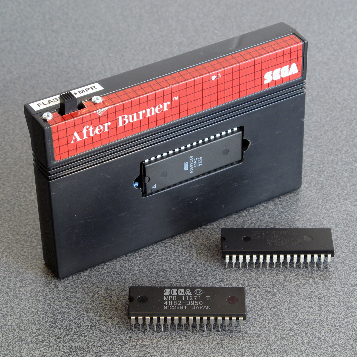
The memory mapper is used to map ROM banks or save RAM on the cartridge into one of three 16KB slots in the Z80's address space. Most Master System cartridges only contain a single chip that combines the ROM data for the game as well as the memory mapper logic. As such, these cartridges can't be modified for use with a generic flash memory chip as you can't access that internal memory mapper. Some cartridges, however, make use of a separate mapper chip and so you can remove the plain mask ROM chip and replace it with a flash memory chip. SMS Power! has this list of mappers and examples of cartridges in which they can be found.
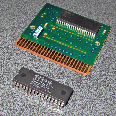
In the photo above you can see where I removed the mask ROM from the cartridge PCB and have left the mapper chip on the board. I didn't want to damage the old ROM chip (in case I wanted to play After Burner again) so I carefully unsoldered it rather than cutting it off the board. To do so I heated up each solder joint on the back of the board and used my spring-loaded solder sucker to remove the molten solder. After this I checked each pin by gently trying to move it in its hole; if it moved I knew it had been unsoldered and if it was stuck fast I knew I needed to try removing more solder. Once all pins were free the old ROM lifted cleanly out of the PCB.
One of convenient features of these cartridges is that the pinout of Sega's mask ROMs is virtually identical to the pinout of commonly-available flash memories like the 29F010 or 49F040. Only two pins need to be changed, as per the information on Charles MacDonald's website:
| Pin | Mask ROM | Flash memory |
|---|---|---|
| 1 | Not connected | A18 |
| 31 | A18 | /WE (Write Enable) |
As I wanted to ensure that the cartridge was compatible with both the original mask ROM and the replacement flash memory chip I thought it best to install a switch to let me select the type of memory that is installed. To break the connection between the solder pad on the PCB and the leg on the memory chip I used an IC socket with legs 1 and 31 bent out and not soldered through their corresponding holes. Wires are soldered to the bent out legs and go via the switch to the corresponding solder pads on the bottom of the PCB.
The position of A18 definitely needed to be swapped between pin 31 on the mask ROM and pin 1 on the flash memory if I wanted to be able to address all 512KB of a 4 megabit ROM. I had heard reports that the write enable pin on the flash memory can be left disconnected however the datasheets for the flash memory chips I checked did seem to indicate that it should be held high during read operations so I thought it best to hold it high when in "flash" mode. This means that the function of both pins needed to be changed by the switch, so I used a DPDT to make this happen. The two different states are illustrated below, showing the connections to the six pins on the bottom of the switch:
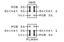
The heavy black lines show the position of the switch contacts when in the upper and lower positions. When in "MPR" mode you can see that pin 31 of the IC socket (A18) is connected to pin 31 of the PCB and pin 1 (NC) of the IC socket is not connected to anything. When in "FLASH" mode pin 31 of the IC socket (now /WE) is connected to Vcc and pin 1 of the IC socket (now A18) is connected to pin 31 of the PCB.
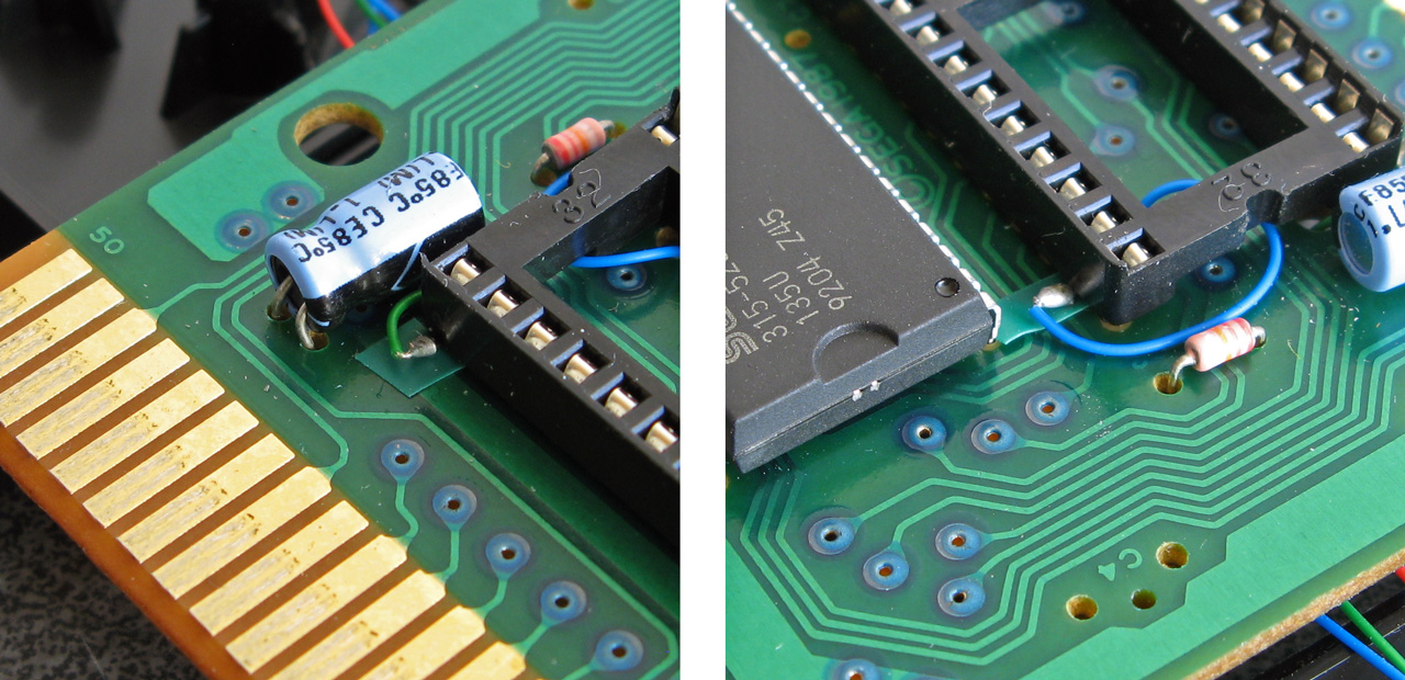
The photos above show how the pins of the IC socket were bent outwards with very fine wires soldered to them. These fine wires run through holes on the PCB under the IC socket to the underside. I did stick very small pieces of electrical insulating tape under the points where the solder joints for the wires attached to the bent pins made contact with the PCB for a bit of added security. With those legs bent out and the wires threaded through the PCB the socket could be soldered down.
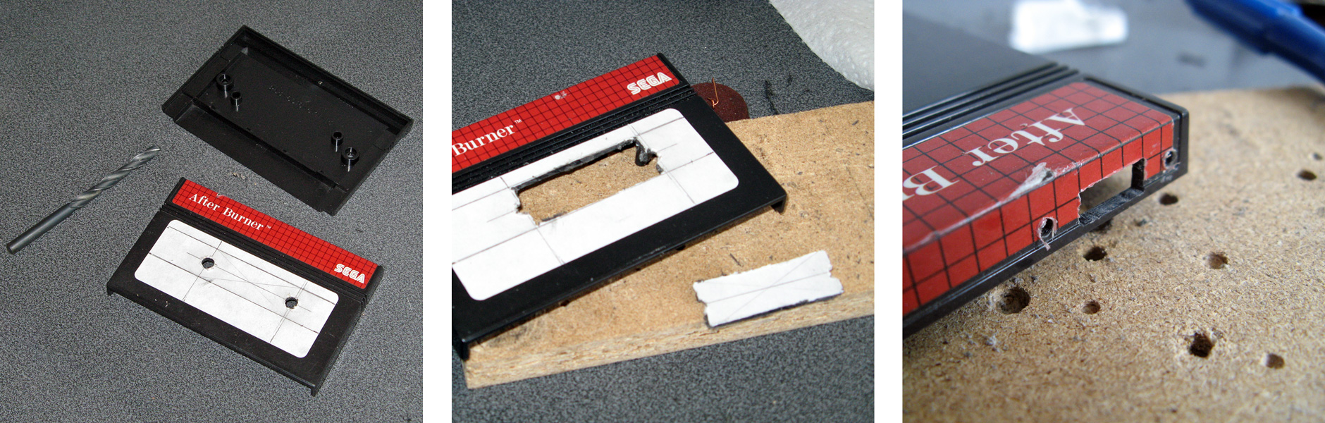
Unfortunately, one problem with using an IC socket is that the extra height means that the PCB no longer fits inside the cartridge shell. I needed to cut a rectangular hole in the cartridge enclosure for the chip to protrude through. I started by drilling two large round holes at the far ends of the chip - this allows me to use a chip puller (or small screwdriver) to pull (or lever) the chip out of the socket without needing to dismantle the cartridge each time. Due to the position of an internal support post very near to the memory chip a larger rectangular slot could not be cut – and I think this looks pretty neat anyway! A smaller rectangular hole was cut in the top of the cartridge shell for the switch to protrude through along with mounting holes for its two screws.
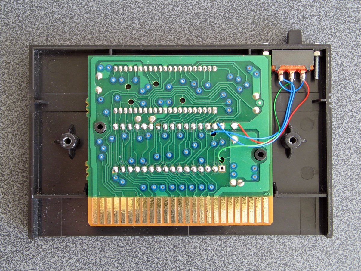
Here the switch has been mounted inside the case with the wires from the IC socket soldered to the appropriate pins on the switch and other wires connected to the appropriate pads on the back of the back of the PCB.
Inserting the original mask ROM for After Burner and setting the switch to MPR mode lets me play After Burner; writing a ROM image to a flash memory chip and inserting that with the switch set to FLASH mode let me run that program instead. Putting the switch on the wrong mode would take me to the console's built-in game of Hang On as the BIOS is no longer able to read the cartridge as a valid Master System game (at least when using a 512KB memory that requires A18 to be connected to the right pin). All in all I'm now happy that I have a way to run programs on my Master System from flash memory and do some homebrew experiments of my own on real hardware.
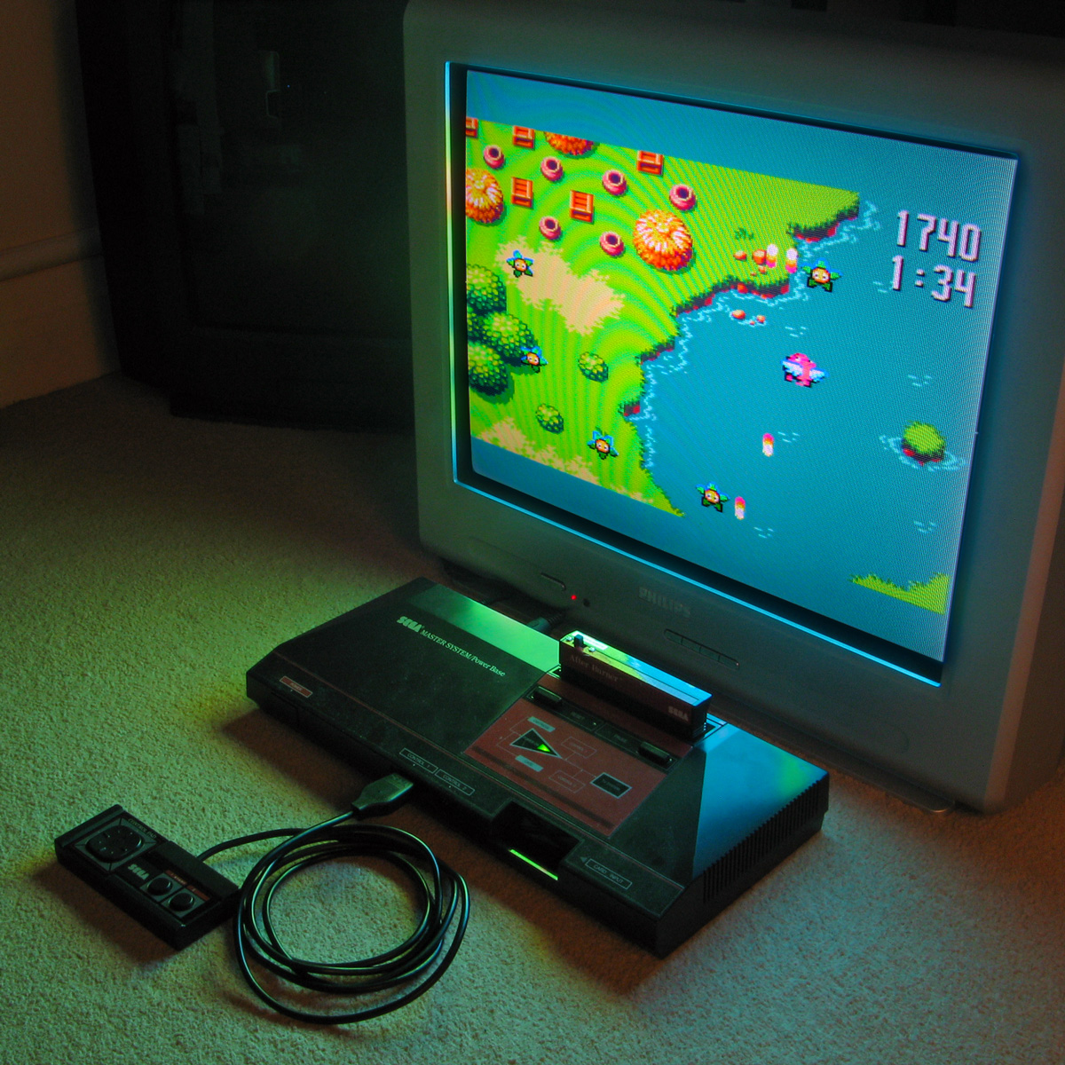
The above photo shows the excellent homebrew Flight of Pigarus by Kagesan running on my Master System courtesy of the modified cartridge. I've tested it so far with an AM29F010B (128KB/1 megabit) and an AT49F040 (512KB/4 megabit) and have been using the Willem programmer (along with Remapped IO.DLL to get it to work with my PC's PCI parallel port) to program the chips.
A temporary solution for 3D games on the Master System without the 3D glasses adaptor
Monday, 29th July 2019
I bought my Sega Master System-compatible 3D glasses almost exactly ten years ago for use in my LCD Shutter Glasses Adaptor project.
More recently I've acquired a CRT television and an actual Sega Master System so I could in theory make use of the glasses as I had originally intended - with Sega Master System games.
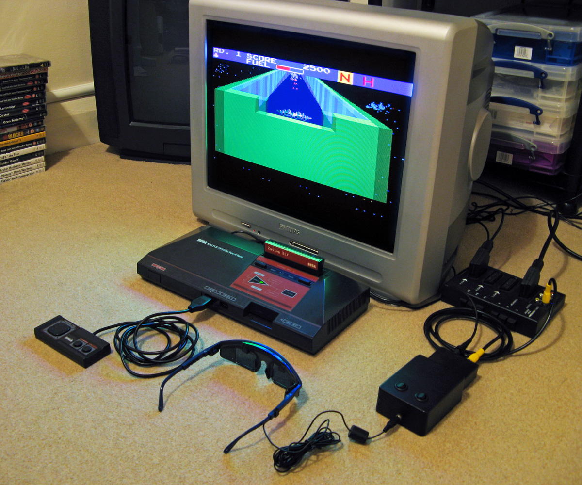
I've been keeping an eye on eBay for the 3D Glasses Adaptor for the Master System. This is a device that plugs into the console's card slot and allows it to drive the glasses with the software controlling which LCD shutter is open and which is closed by writing to the card. Unfortunately, these cards are not too easy to find in the UK and when they do appear they usually came bundled with a broken pair of glasses (it seems very unusual for both arms to still be attached to the glasses, and I've seen a fair few pairs that are cracked down the middle too). I already own some compatible 3D glasses so didn't want to waste money on buying a broken set of original Master System ones!
I did eventually find someone selling a loose adaptor for a reasonable price so bought it and a few games. Zaxxon 3-D was the first to arrive and I was eager to test it out. Without the card adaptor I needed to find an alternative solution, so my thoughts turned to the LCD Shutter Glasses Adaptor I'd built a few years ago.
This is designed to sit between a PC and a VGA CRT monitor and drives the shutter glasses, alternating which LCD shutter is open and which is closed every vertical sync. It can also blank out alternate scanlines, simulating an interlaced signal from a progressive one by blanking odd scanlines on one frame and even scanlines on the next, but this is not useful in our case. The Master System is already alternating complete left and right eye views on its own, so we just need to catch its equivalent of a vsync pulse and feed that into the VGA port on the back of the shutter glasses adaptor.
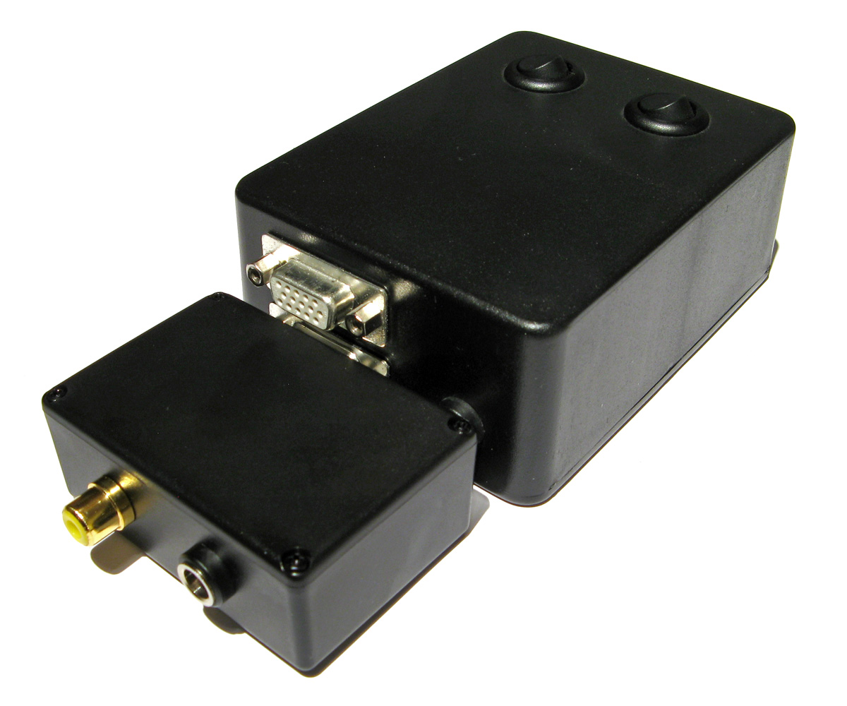
Above is the device I built, attached to the existing 3D glasses adaptor. It has a single composite input which should be connected to the composite output from the console, either via a splitter (if the console is connected to the TV using composite video) or via some sort of SCART breakout box (I'm using the composite video output from my SCART switch box). It also has a power socket which is used to power the circuit inside which is also passed through to the LCD shutter glasses adaptor. The box has a DE-15 connector and 5.5x2.1mm barrel plug on the other side for connections:
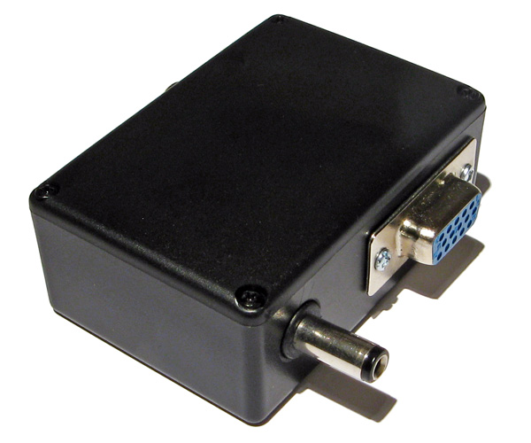
I'd cut the barrel plug off a faulty power supply years ago, I'm glad I kept it as it made the project a much neater solution than it might have other been!
The circuit inside is very simple indeed. As the original adaptor has its own 5V regulator inside and is designed to be powered from a 9V power supply I had to maintain the same convention for this device, so I use a 7805 regulator to convert the incoming voltage to 5V. This powers a textbook example of an LM1881 sync separator circuit - I'm using the reference circuit from the chip's datasheet, connecting the composite video input to the chip's composite video input via a 0.1µF capacitor (without termination as it's assumed the signal is being terminated by the TV) and I use the LM1881's composite sync output and vertical sync output for the VGA connector's horizontal and vertical sync connections respectively.

The circuit can be seen above, stuffed in the bottom of the box - along with copious amounts of hot glue to keep the barrel plug in place! How well does it work? Well, the below animation shows two views of the circuit in action, viewed through first one shutter and then the other of the 3D glasses:
This isn't a perfect solution - the Master System expects to be able to explicitly specify which shutter is open whereas in our case we're simply be alternating every frame. This could mean that the eyes are swapped, however there is an eye swap switch on the shutter glasses adaptor to compensate. If the view looks wrong then the switch can be used to correct it, and once that's done as long as the software alternates the views every frame then it should be fine.
I'm certainly happy for now, as it lets me play my 3D games whilst waiting for the console's intended 3D glasses adaptor to arrive in the post.
New 3D renderer in Cogwheel
Monday, 10th August 2009
I have written a new 3D-compatible renderer for Cogwheel. It holds two textures, one for each eye, and uses one of a number of different effect file techniques to mix the two views.

Based on the interlacing work from the previous entry, the first technique is one that uses interleaved rows. I'm not really sure if there's a good way to convert texture coordinates into device coordinates, so am passing in the viewport height as a parameter and hoping that floating point errors don't trip me up (they haven't, yet).
float4 RowInterleavedPixelShader(VertexPositionTexture input) : COLOR0 {
	float row = input.Texture.y * ViewportHeight * 0.5f;
	if (abs(round(row) - row) < 0.1f) {
		return tex2D(LeftEyeSampler, input.Texture);
	} else {
		return tex2D(RightEyeSampler, input.Texture);
	}
}
Alternate pixel centres may also pose a problem in the future. If anyone had any recommendations, suggestions or warnings on the way I'm detecting the evenness or oddness of a particular "scanline" then I'd appreciate hearing them!
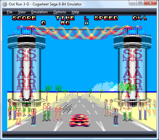
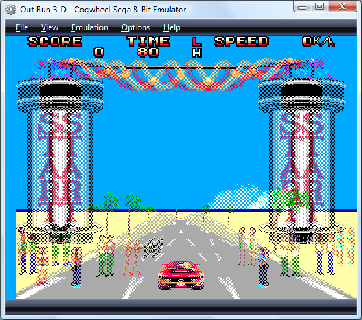
I have also added two other interleaving modes; one in columns and another in a chequerboard pattern. I included these two as I've seen that some 3D LCD panels use a column interleaving pattern (I suppose that with a lenticular lens in front of such a panel you may not even need 3D glasses) and apparently Sharp have displays that use the chequerboard pattern.
I have also taken advantage of pixel shaders to create colour and monochrome anaglyphs (previously calculated in software), though neither look as good as the above full-colour modes for shutter glasses or similar hardware.
There are a few issues I need to sort out first before I can release this; for example, there's no way to set whether the first row/column/pixel is for the left or right eye. More problematic is the removal of support for non power-of-two textures; the Master System's 256×192 display is fine, but the Game Gear's 160×144 display gets rounded up to 192 pixels wide (and yes, I know that's not a power of two) on my video card. I also mean to give Promit's SlimTune profiler a look to see if I can optimise some of the less efficient pieces of my code. The C# version of emu2413 is probably a good candidate, being a "dumb" translation from the original macro-heavy C.
C# emu2413
Thursday, 8th January 2009
This is fairly embarrassing; somebody sent me an email that was flagged as spam which I accidentally deleted. So if you sent me an email and I haven't replied, I'm not deliberately being rude; could you send it again? 
After encountering strange crashes (not .NET exceptions, full out crashes) with emu2413 I decided to port it to straight C# instead from its existing C incarnation (emu2413.h.cs and emu2413.c.cs). Even though the original was macro-heavy it was relatively simple to port, and so there's no dependency on an unmanaged DLL to generate FM sound any more. However, the C# version is significantly slower (Cogwheel now takes about 50% extra CPU time when FM sound is enabled), possibly due to many extraneous method calls that were macros in the original.
However, the emulator still crashes when FM sound is enabled. And I have no idea why, as it only happens in Release mode and outside the IDE. The Debug build works fine inside and outside the IDE, and Release mode works fine when run within the IDE. 
Controller input updates to Cogwheel
Monday, 5th January 2009
I hope you all had a good Christmas and New Year period!
I received an Xbox 360 controller for Christmas, so have done a bit of work on Cogwheel to add support for it. (You can download a copy of the latest version 1.0.2.0 with SlimDX here).
The first issue to deal with was the D-pad on the Xbox 360 controller. When treated as a conventional joystick or DirectInput device the D-pad state is returned via the point-of-view (POV) hat. The joystick input source class couldn't raise events generated by the POV hat so support for that had to be added. This now allows other controllers that used the POV hat for slightly bizarre reasons (eg the faceplate buttons on the PlayStation controller when using PPJoy) to work too.
The second issue was the slightly odd way that the Xbox 360's DirectInput driver returns the state of the triggers - as a single axis, with one trigger moving the axis in one direction, the other trigger moving it in the other. You cannot differentiate between both triggers being held and both being released, as both states return 0. To get around this, I've added support for XInput devices, where all buttons and triggers operate independently.
The Xbox 360 controller now shows up twice in the UI - once as an XInput device and again as a conventional joystick. Fortunately, you can check if a device is an XInput device by the presence of IG_ in its device ID. Here's some C# code that can be used to check with a joystick is an XInput device or not.
using System.Globalization;
using System.Management;
using System.Text.RegularExpressions;

namespace CogwheelSlimDX.JoystickInput {

    /// <summary>
    /// Provides methods for retrieving the state from a joystick.
    /// </summary>
    public class Joystick {

        /* ... */

        /// <summary>
        /// Gets the vendor identifier of the <see cref="Joystick"/>.
        /// </summary>
        public ushort VendorId { get; private set; }

        /// <summary>
        /// Gets the product identifier of the <see cref="Joystick"/>.
        /// </summary>
        public ushort ProductId { get; private set; }

        /* ... */

        /// <summary>
        /// Determines whether the device is an XInput device or not. Returns true if it is, false if it isn't.
        /// </summary>
        public bool IsXInputDevice {
            get {
                var ParseIds = new Regex(@"([VP])ID_([\da-fA-F]{4})"); // Used to grab the VID/PID components from the device ID string.

                // Iterate over all PNP devices.
                using (var QueryPnp = new ManagementObjectSearcher(@"\\.\root\cimv2", string.Format("Select * FROM Win32_PNPEntity"), new EnumerationOptions() { BlockSize = 20 })) {
                    foreach (var PnpDevice in QueryPnp.Get()) {

                        // Check if the DeviceId contains the tell-tale "IG_".
                        var DeviceId = (string)PnpDevice.Properties["DeviceID"].Value;
                        if (DeviceId.Contains("IG_")) {

                            // Check the VID/PID components against the joystick's.
                            var Ids = ParseIds.Matches(DeviceId);
                            if (Ids.Count == 2) {
                                ushort? VId = null, PId = null;
                                foreach (Match M in Ids) {
                                    ushort Value = ushort.Parse(M.Groups[2].Value, NumberStyles.HexNumber);
                                    switch (M.Groups[1].Value) {
                                        case "V": VId = Value; break;
                                        case "P": PId = Value; break;
                                    }
                                }
                                if (VId.HasValue && this.VendorId == VId && PId.HasValue && this.ProductId == PId) return true;
                            }
                        }
                    }
                }
                return false;
            }
        }

        /* ... */
    }
}
When the joysticks are enumerated they are only added to the input manager if they are not XInput devices.
To round up the entry, here's a screenshot of a minesweeper clone I've been working on in BBC BASIC.

You can view/download the code here and it will run in the shareware version of BBC BASIC for Windows. The code has been deliberately uglified (cramming multiple statements onto a single line, few comments, trimmed whitespace) to try and keep it within the shareware version's 8KB limit as this is a good limit to keep in mind for the TI-83+ version too.
Sega Master System emulation in Silverlight
Monday, 15th December 2008
I've had to quickly learn Silverlight for work recently, which has been an interesting experience. I've had to write new code, which is fine but doesn't really excite me as far as Silverlight is concerned - it doesn't really matter which language new code is developed in, as long as it gets the job done.
What does interest me more is that Silverlight is ".NET in your browser", and I'm a big fan of .NET technology with a handful of .NET-based projects under my belt. Silverlight therefore gives me the opportunity to run these projects within the browser, which is a fun idea. 
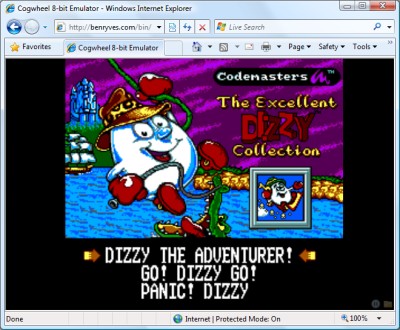
To this end, I've turned Cogwheel, a Sega 8-bit system emulator, into a Silverlight application. It took about an hour and a half, which was not as bad as I'd expected! (Skip to the bottom for instructions for the demo).
Raster graphics
Silverlight's raster graphics support is somewhat lacking. You can display raster graphics in Image elements, but - as far as I can see - that's about it. If you wish to generate and display images dynamically via primitive pixel-pushing, you're out of luck as far as Silverlight's class library is concerned.
Thankfully, Ian Griffiths has developed a class named PngGenerator that can speedily encode a PNG from an array of Colors that can then be displayed in an Image. Cogwheel's rasteriser returns pixel data as an array of integers so there's a small amount of overhead to convert these but other than that it's easy to push pixels, albeit in a fairly roundabout manner.
Render loop
The render loop is based around an empty Storyboard that invokes an Action every time it completes then restarts itself.
using System;
using System.Windows;
using System.Windows.Media.Animation;

namespace Cogwheel.Silverlight {

    public static class RenderLoop {

        public static void AttachRenderLoop(this FrameworkElement c, Action update) {
            var Board = new Storyboard();
            c.Resources.Add("RenderLoop", Board);
            Board.Completed += (sender, e) => {
                if (update != null) update();
                Board.Begin();
            };
            Board.Begin();
        }

        public static void DetachRenderLoop(this FrameworkElement c) {
            var Board = (Storyboard)c.Resources["RenderLoop"];
            Board.Stop();
            c.Resources.Remove("RenderLoop");
        }

    }
}
I'm not sure if this is the best way to do it, but it works well enough and is easy to use - just grab any FrameworkElement (in my case the Page UserControl) and call AttachRenderLoop:
private void UserControl_Loaded(object sender, RoutedEventArgs e) {
    this.UserControlRoot.AttachRenderLoop(() => {
        /* Update/render loop in here. */
    });
}
Missing .NET framework class library features
This is the big one; Silverlight does not cover the entire .NET framework class library, and so bits of it are missing. Fortunately this can be resolved, the difficulty depending on how you want the functionality of the original app to be affected.
Missing types you're not interested in.
These are the easiest to deal with, and this includes attributes and interfaces that the existing code uses that you're not especially interested in. For example, Cogwheel uses some of .NET's serialisation features for save states - a feature I wasn't intending on implementing in the Silverlight version. The [Serializable] and [NonSerialized] attributes are not available in Silverlight, nor is the IDeserializationCallback interface. To get the project to compile some dummy types were created.
namespace System {

    class SerializableAttribute : Attribute { }
    class NonSerializedAttribute : Attribute { }

    interface IDeserializationCallback {
        void OnDeserialization(object sender);
    }

}
Missing types or methods that you don't mind partially losing.
Cogwheel features some zip file handling code that uses System.IO.Compression.DeflateStream, a class not available in Silverlight. Rather than remove the zip classes entirely (which would require modifications to other files that relied on them) it was easier to use conditional compilation to skip over the DeflateStream where required.
switch (this.Method) {
    case CompressionMethod.Store:
        CompressingStream = CompressedStream;
        break;

    #if !SILVERLIGHT
    case CompressionMethod.Deflate:
        CompressingStream = new DeflateStream(CompressedStream, CompressionMode.Compress, true);
        break;
    #endif

    default:
        throw new NotSupportedException();
}
Missing instance methods.
C# 3.0 adds support for extension methods - user-defined methods that can be used to extend the functionality of existing classes that you cannot modify directly. Silverlight is missing a number of instance methods on certain classes, such as string.ToLowerInvariant();. By using extension methods the missing methods can be restored.
namespace System {

    public static class Extensions {
        public static string ToLowerInvariant(this string s) { return s.ToLower(CultureInfo.InvariantCulture); }
        public static string ToUpperInvariant(this string s) { return s.ToUpper(CultureInfo.InvariantCulture); }
    }

}
Missing static methods.
These are the most work to fix as extension methods only work on instance methods, not static methods. This requires a change at the place the method is called as well as the code for the method itself.
I've got around this by creating new static classes with Ex appended to the name then using using to alias the types. For example, Silverlight lacks the Array.ConvertAll method.
namespace System {

    static class ArrayEx {
        public static TOut[] ConvertAll<TIn, TOut>(TIn[] input, Func<TIn, TOut> fn) {
            TOut[] result = new TOut[input.Length];
            for (int i = 0; i < input.Length; i++) {
                result[i] = fn(input[i]);
            }
            return result;
        }
    }

}
First, a replacement method is written with Ex appended to the class name. Secondly, any file that contains a reference to the method has this added to the top:
#if SILVERLIGHT
using ArrayEx = System.ArrayEx;
#else
using System.IO.Compression;
using ArrayEx = System.Array;
#endif
Finally, anywhere in the code that calls Array.ConvertAll is modified to call ArrayEx.ConvertAll instead. When compiling for Silverlight it calls the new routine, otherwise it calls the regular Array.Convert.
Demo
The links below launch the emulator with the selected ROM image.
To run your own ROM image, click on the folder image in the bottom-right corner of the browser window to bring up a standard open file dialog.
Zip files are not handled correctly, but if you type *.* into the filename box, right-click a zip file, pick Open, then select the ROM from inside that it should work (it does on Vista at any rate).
The cursor keys act as you'd expect; Ctrl or Z is button 1/Start; Alt, Shift or X is 2 (Alt brings up the menu in IE). Space is Pause if you use an SMS ROM and Start if you use a Game Gear ROM. Keys don't work at all in Opera for some reason, but they should work fine in IE 8 and Firefox 3. You may need to click on the application first!
Issues
There are a number of issues I have yet to address. Performance is an obvious one; it's a little choppy even with 100% usage of one the cores on a Core 2 Duo. Sound is missing, and I'm not sure what Opera's doing with keys. Other than that, I thought it was a fun experiment.
Once I've tidied it up a bit I'll merge the source code with the existing source repository.
3D glasses and CPU cycle counting
Monday, 7th April 2008
I reintroduced joystick support to the emulator front-end over the weekend, using a much more sensible input manager. The control editor form uses the same interface design for keyboard and joysticks - you click the button you wish to edit, it appears pressed, you press the key (or joystick button) you wish to bind to it and it pops back out again. It'll also check to see if you've moved the joystick in a particular direction on any of its reported axes.
Another feature I added was better support for games that used the 3D glasses, using a simple red-cyan anaglyph output blender.
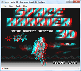
If the memory address range that the glasses respond to has been written to within the last three frames, it switches to the blending mode.
Irritatingly, with one glaring bug fix I managed to lower overall compatibility. Some instructions weren't being timed correctly (or at all) meaning that the emulator was executing too many instructions for the number of clock cycles it was asked to run. During the time each video scanline is run, 228 CPU cycles are executed. Upping this to 248 cycles (just for experimentation) fixes all known bugs - including the long-standing flickering pixels at the top of the screen in Cosmic Spacehead and display corruption in GP Rider. (However, digitised speech plays at a noticably higher pitch).
I'm not entirely sure why this is - it could be that some instructions are claiming to take too long, it could be yet another interrupt problem. To call this mildly frustrating is a bit of an understatement!
Sound, at long last.
Friday, 7th March 2008
I have finally got around to adding sound to Cogwheel using Ianier Munoz's waveOut API wrapper.

The technique used is fairly simple. I start with a sound buffer that is a multiple a number of video frames in length (1/60th of a second is one frame) - four seems a good number. This buffer needs to be periodically topped up with sound samples (every four frames in the above example).
I run the emulator for one frame, then generate a frame's worth of audio. I add these samples to a queue. The sound callback then periodically dequeues these samples and appends them to its buffer.
// This is called once every video frame.
// 735 samples at 44100Hz = 1/60th second.
// (Multiplied by two for stereo).
this.Emulator.RunFrame();
short[] Buffer = new short[735 * 2];
this.Emulator.Sound.CreateSamples(Buffer);
this.GeneratedSoundSamples.Enqueue(Buffer);
The important thing is that the sound is always generated after the video frame (and thus after any hardware writes). I log writes to the sound hardware over the period of a frame (along with the number of CPU cycles that have elapsed), then space them out when generating the sound samples so that they play in synch. My previous problems were caused by the sound emulation trying to "look ahead" past what had already been generated.
However, there is a potential problem with this - as the video and sound emulation are not locked in synch with eachother, there are two cases that could crop up:
- The emulator runs faster than 60Hz, generating too many sound samples.
- The emulator runs slower than 60Hz, not generating enough sound samples.
The first is the easiest to deal with. In most instances you'd want a couple of extra frames of sound data left in the queue after topping up the sound buffer, in case in the next period not enough are generated. However, if I notice that the queue is longer than entire sound buffer after topping it up, I clear it completely. This would make the sound a little choppy, but so far this hasn't happened in my tests.
The latter is a little more complex. If I just left it the sound buffer would have gaps in it, causing noticable pops (this I have noticed in some of the more processor-intensive games). To cover up the gaps, I generate enough extra frames of sound data to fill the gap. As no sound hardware writes are made, this has the effect of extending any tones that were currently playing, so the sound will play back slightly out of time. However, slightly out of time by a few 60ths of a second is a better solution than a pop.
// This is called when the sound buffer needs topping up.
// That's about once every four frames.
private void SoundBufferFiller(IntPtr data, int size) {

	// Temporary buffer to store the generated samples.
	short[] Generated = new short[size / 2];

	for (int i = 0; i < Generated.Length; i += 735 * 2) {
		if (this.GeneratedSoundSamples.Count > 0) {
			// We've already queued up some sound samples.
			Array.Copy(this.GeneratedSoundSamples.Dequeue(), 0, Generated, i, 735 * 2);
		} else {
			// Erk, we're out of samples... force generate some more and use those instead.
			// (This avoids popping).
			short[] Temp = new short[735 * 2];
			this.Emulator.Sound.CreateSamples(Temp);
			Array.Copy(Temp, 0, Generated, i, 735 * 2);
		}
	}

	// Copy to the sound buffer.
	Marshal.Copy(Generated, 0, data, size / 2);

	// If too many samples are being generated (FPS > 60Hz) then make sure it doesn't go out of control.
	while (this.GeneratedSoundSamples.Count > this.SoundBufferSizeInFrames) this.GeneratedSoundSamples.Dequeue();

}
Joysticks and Game Genie codes
Monday, 3rd March 2008
The biggest update to the emulator relates to input.
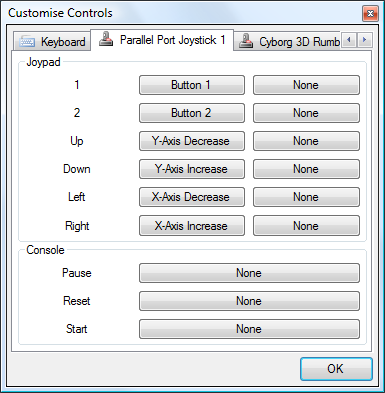
I've added a new control panel that lets you customise key bindings. For the keyboard, you simply click on the button you wish to customise, then press the key on your keyboard you wish to bind. As you can probably tell from the screenshot, I've also added joystick support (via the Multimedia Joystick Functions with a bit of P/Invoke for ease) which means that with a simple adapter and a free driver you can use original SMS pads with the emulator.
I haven't added support for the POV hat, which needs doing as the PPJoy PlayStation controller driver exposes the d-pad as a POV hat.
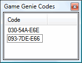
I've also added an interface for adding Game Genie codes. The Game Genie was a cheating device that could be used to patch memory.
I have also started reintroducing (albeit in a slightly buggy fashion) multiple memory devices. Previously I've just been emulating a cartridge ROM and work RAM; the real consoles had multiple memory devices including a card slot, ROM BIOS and expansion slots. By emulating this system one can boot with the original BIOS, and (for example) not insert a cartridge to watch the BIOS animation or play its integrated game.
For ease, there's a quick-load ROM menu option that will load anything into the cartridge slot and disable all others for quick game playing. For those who wish to play with the hardware more, there's an "advanced load" dialog that will let you pick what goes in which slot, and also force various options (such as locale, hardware model, video system and so on) instead of the automatically guessed options. I'd also like it to be able to pick patch files (such as translations) so you don't need to use an external tool. Currently this dialog only supports cartridge ROM and BIOS ROM loading, though.
Cogwheel on Google Code
Sunday, 24th February 2008
On bakery2k1's suggestion, I took a look at my sprite collision flag code. It only checked for collisions between sprites appearing in the foreground - sprites that were hidden behind a background tile weren't checked, which caused the Fantastic Dizzy bug.
I have decided to give Google's free project hosting a whirl. As usual, they can't get it working in Opera  (no big surprises there) and it's horrifically slow, but I can't really complain given that it's free, and the issue tracking is pretty handy.
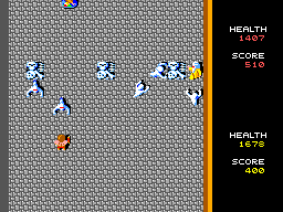
Another game that has been fixed is the conversion of that arcade classic, Gauntlet. This was partially due to buggy controller port emulation, but a long-standing bug has been the lack of the y-scrolling inhibition flag. Games could set a flag on the VDP that would prevent the rightmost 64 pixels from scrolling vertically - this is useful to create a locked status bar on the right for a vertical scrolling game, for example.
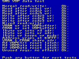
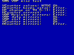
I'm slowly getting there with FluBBa's VDP tester...
/INTerminable Interrupt Problems
Friday, 22nd February 2008
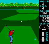
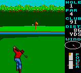
World Class Leaderboard Golf
Well, I've just about got it the way it was before with the new interrupt code; most games work again, but the few that have always given problems (such as Desert Speedtrap) still don't work properly. I think this is the stage where I have to start trawling through disassemblies to try and work out why they're not working.
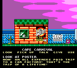
One problem I still haven't got to the bottom of is with the Dizzy games. They either reset when starting a new game or lock up. I'm hoping this is a problem with my implementation of the Codemasters mapper. I guess that The Excellent Dizzy Collection has a simple front-end game selection screen that switches to the requisite ROM page for the selected game, then jumps to the start of that page - in my case this jumps back to the initial Codemasters screen.
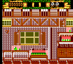
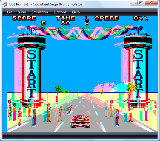
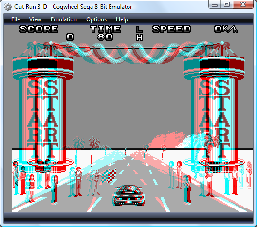
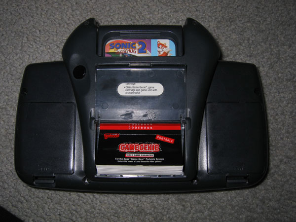
I'm not sure where Fantastic Dizzy's problems originate. It looks like an interrupt problem (maybe the palette should be switched when the VDP has finished with the status bar at the top?), but could also be related to the other Codemasters problems.
Interestingly, Micro Machines (1 and 2) and Cosmic Spacehead - both using the Codemasters ROM mapper - seem to work fine.
Interrupts: A Fresh Start
Thursday, 21st February 2008
I gave in and rewrote all of the Z80's interrupt emulation from scratch, finding some rather horrible bugs in the existing implementation as I went.
Some of the highlights included non-maskable interrupts ignoring the state of the IFF1 flag (this flag is automatically cleared when an interrupt is serviced, and is used to prevent the interrupt handler from being called again before it has finished) and the RETN instruction not copying the state of the IFF2 flag back to IFF1. When non-maskable interrupts are serviced, the state of IFF1 is copied to IFF2 before it gets cleared, the idea being that if you use RETN interrupts are automatically re-enabled on exit of the NMI ISR. (Contrast this with maskable interrupts, where both flags are cleared, and you need an explicit EI to re-enable them).
The HALT instruction (executes NOPs until an interrupt is requested or the CPU is reset) was also completely incorrectly (and bizarrely) implemented. The rewrite just sets a Halted property, which prevents the CPU from fetching or executing any instructions. The interrupt-triggering code simply resets this property.
This has fixed numerous bugs (I'm not sure when they were introduced, as it was all working a while back). It's gone from "not working at all" to "just about working", but some games or demos that rely on precise interrupt timing don't work properly.


Game Gear Hicolor Demo and Desert Speedtrap
Both problems in the above screenshots relate to line-based interrupts from the VDP (Video Display Processor). Some other games simply hang at startup.
Loading ROMs
Wednesday, 20th February 2008
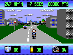
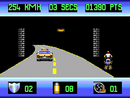
OutRun Europa
I've been adding a series of new features to Cogwheel. I wrote a basic zip file class a while back (only supporting store and deflate compression - the majority of zip files use deflate), and have added a Utility namespace with methods for help with loading ROMs.
For example, there is a method that is passed a filename by reference, and it'll return an array of bytes of the loaded file. If the passed filename was a zip file, by any chance, it'll search for ROMs inside the zip, and modify the filename (so it might end up as C:\Path\SomeFile.zip\Game.sms).
Once this is done, the CRC-32 checksum of the file is calculated then looked up against a database of known ROM dumps. I'm currently using the SMS Checker .romdata files as the database source. These contain information about known bad dumps, and can be used to strip headers and footers, patch bytes and remove redundant overdump data to end up with a valid ROM image.
Finally, the mapper is detected. Currently, I have three mappers - RAM (which is just 64KB of RAM), Standard (the standard Sega Master System ROM mapper) and Codemasters. I use the RAM mapper for all SG-1000 and SC-3000 games (I'm not sure what they're meant to use, here, but some games - such as The Castle - don't work with the standard SMS mapper).
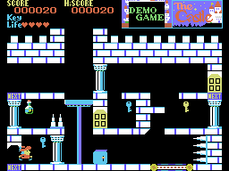
The Codemasters mapper uses a different method to swap pages, which means that the conventional SMS BIOS checksumming code fails to swap in pages correctly and thus doesn't check the entire cartridge. The games therefore have their own checksumming routines and store their own checksum in a Codemasters-specific header; this makes detecting Codemasters games fairly easy, as all you need to do is check for the extra Codemasters checksum.
As the BIOS doesn't check the checksum, the cartridge provides code to do so itself. You can run it by holding 1 and 2 down as the game boots.
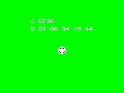
The Excellent Dizzy Collection
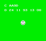
Micro Machines
I seem to have broken interrupts somewhere along the line; most noticable are non-maskable interrupts (as generated by the Pause button) which crash the emulator (it appears that once they fire, interrupts are never re-enabled). I'm not sure what's causing this, but hopefully it won't be too unpleasant to fix!
Necromancy
Friday, 8th February 2008
After seeing Scet and Drilian's work on their respective emulator projects I decided I needed to do something with the stagnating Cogwheel source on my hard disk drive.
The only ROM I have tested where I can't find an explanation for a bug is the Game Gear Garfield: Caught in the Act game. Like many games, when left at the title screen it'll run a demo loop of the game in action. At one point Garfield would walk to the left of the screen, jump over a totem pole, shunt it to the right and use it as a way to jump out of a pit. However, in Cogwheel he would not jump far enough to the left, and not clearing the totem pole he'd just walk back to the right and not have anything to jump out of the pit on.
I remembered a post on MaxCoderz discussing a long-standing tradition of thinking that when a JP <condition>, <address> failed the instruction took a single clock cycle. You can see this misreported here, for example. This document, on the other hand, claims it always takes 10 clock cycles - and most importantly of all, the official user manual backs this up.
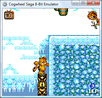
So, Garfield can now get out of his pit. The user interface has changed (again) - I'm now using SlimDX to dump pixels to a Panel, which seems to be the least hassle distribution-wise and doesn't throw LoaderLockExceptions.
Subscribe to an RSS feed that only contains items with the Sega Master System tag.