BBC BASIC's improved filling, *EXEC and Lights Out
Thursday, 13th November 2008
Progress on the TI-83+/TI-84+ port of BBC BASIC continues - I'm hoping to get a beta release out soon. 


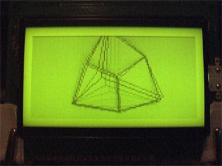
I've done quite a lot of work on the graphics features. Every shape that is plotted can be set to either the foreground colour, background colour or to invert the pixels it covers. This wasn't implemented properly (everything was always drawn in the foreground colour) which has been corrected.
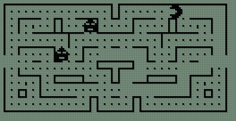
The first image in the above group shows the flood-filler in action, filling inside and outside a triangle. The second image demonstrates the ellipse drawing and filling code by qarnos. It had a small amount of overdraw, which is not normally a problem, but in an inverting plot mode drawing a pixel twice causes it to reset to its original value. This ends up leaving gaps in the circle. Fortunately he was able to give me a lot of help in fixing it.
The third image demonstrates a non-standard feature I've added - being able to set your own fill patterns. The GCOL statement lets you set the foreground or background colour, and for values between black and white a dithered fill pattern is substituted instead. GCOLPAT takes a pointer to an 8×8 pixel fill pattern and subsequent fill operations will use that instead; passing FALSE (0) to GCOLPAT or setting a colour normally via GCOL reverts to the standard dither fills.
I've also done a small amount of benchmarking. There's a sample program in the TI-83+ guidebook that draws a Sierpinski triangle.

On a regular 6MHz TI-83+, the TI program takes 7 minutes and 8 seconds to run. A direct translation to BBC BASIC executes in 2 minutes and 21 seconds, and a simplified version executes in 1 minute and 56 seconds.

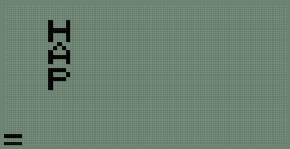
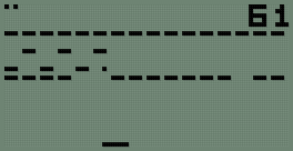
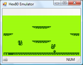
I'm also trying to improve the number of OS-level "star" commands. Above is a demonstration of *EXEC which reads console input from a text file. A file is opened for output using OPENOUT, some text is written into it using PRINT#, and then it it *EXECuted. This is one possible way of converting a text file into a BBC BASIC program.

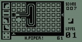
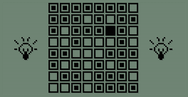
Finally, I'm trying to write a game as an example program. The above screenshot shows an incomplete clone of the Lights Out game by Tiger Electronics.
TIME$ to resume work on TI-83+ BBC BASIC
Wednesday, 29th October 2008
It's been a while since I worked on the TI-83+ calculator port of BBC BASIC, and due to a relatively modular design some of the new features I'd been working on for the Z80 computer project version could be easily transferred across.
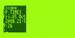
The first addition to the calculator port is the TIME$ keyword, which lets you get or set the system time.


That's all very well and good, but only the TI-84+ calculator has real-time clock hardware - the TI-83+ doesn't have any sort of accurate timekeeping to speak of. Rather than display an error when TIME$ is used I opted to use an inaccurate software-based clock. It uses the TI-83+'s timer interrupts (roughly 118Hz) to update the date and time about once a second. The clock is reset to Mon,01 Jan 2001.00:00:00 every time BBC BASIC is restarted and keeps abysmal time, but software designed to use the clock will at least run.
I have been transferring and amending documentation from Richard Russell's website to a private installation of MediaWiki. There are about 120 entries so far; having documentation puts me much closer to being able to make a release.
I have also fixed a handful of bugs. One that had me tearing my hair out was something like this:
  250 DEF PROC_someproc(a,b)
  260 a=a*PI
  270 ENDPROC
The program kept displaying a No such variable error on line 260. Well, a is clearly defined, and retyping the procedure in another program worked, so what was the problem here? I thought that maybe one of the graphics calls or similar was corrupting some important memory or modifying a register it shouldn't. It turns out that the problem lay in the Windows-based tokeniser - it was not picking up PI as a token, for starters, and was storing the ASCII string "PI" instead. On top of that, it was treating anything after a * as a star command, which aren't tokenised either. (Star commands, such as *REFRESH, are passed directly to the host interface or OS). Retyping the problematic lines caused BBC BASIC to retokenise them, which was why I couldn't replicate the problem in other programs. By fixing the tokeniser, everything started working again.
The source code for the analogue clock program is listed below.
   10 *REFRESH OFF
   20 VDU 29,48;32;
   30 GCOL 0,128
   40 REPEAT
   50   t$=TIME$
   60   hour%=VAL(MID$(t$,17,2))MOD12
   70   min%=VAL(MID$(t$,20,2))
   80   sec%=VAL(MID$(t$,23,2))
   90   sec=sec%/60
  100   min=(min%+sec)/60
  110   hour=(hour%+min)/12
  120   CLG
  130   GCOL 0,127
  140   MOVE 0,0
  150   PLOT 153,31,0
  160   GCOL 0,0
  170   FOR h=1TO12
  180     hA= h/6*PI
  190     hX=30*SIN(hA)
  200     hY=30*COS(hA)
  210     MOVE hX,hY
  220     DRAW hX*0.9,hY*0.9
  230   NEXT h
  240   PROC_drawHand(sec,30)
  250   PROC_drawHand(min,24)
  260   PROC_drawHand(hour,16)
  270   *REFRESH
  280 UNTIL INKEY(0)<>-1
  290 *REFRESH ON
  300 END
  310 DEF PROC_drawHand(pos,length)
  320 MOVE 0,0
  330 pos=pos*2*PI
  340 DRAW length*SIN(pos),-length*COS(pos)
  350 ENDPROC
I translated the tokeniser source code to PHP so that by pointing a browser to file.bbcs for a known file.bbc the highlighted, detokenised source code is served as HTML instead. Hurrah for mod_rewrite, and if you're using IIS Ionic's Isapi Rewrite Filter performs a similar job using the same syntax.
Z80 computer - Lines, cubes and inverted text
Sunday, 5th October 2008
I've made a few additions to the operating system for the computer. The Console module, which handles text input and output, now supports "coloured" text - that is you can set the text foreground and background colours to either black or white. This functionality is exposed via the BBC BASIC COLOUR statement. If you pass a value between 0 and 127 this sets the foreground colour (0..63 is white, 64..127 is black) and if you pass a value between 128 and 255 this sets the background colour (128..191 is white, 192..255 is black).
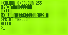
The image on the right also demonstrates another addition - you can set the text viewport to occupy a partial area of the display. This is most useful when coupled with the ability to define graphics viewports, which I have yet to add.
That said, I have started writing the Graphics module. So far all it can do is draw clipped lines, and this functionality is exposed via BBC BASIC's MOVE and DRAW statements. MOVE sets the graphics cursor position - DRAW also moves the graphics cursor, but also draws a line between the new position and the previously visited one.

I cannot use drawing code I've written for the TI-83+ version due to differences in the LCD hardware and the way that buffers are laid out. The popular way to lay out graphics buffers on the TI-83+ is as follows:
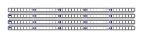
Each grey block represents 8 pixels - one byte in LCD memory represents 8 pixels grouped horizontally. The leftmost bit in each 8-pixel group is the most significant bit of each byte. The data is stored in the buffer so that each row of the LCD is represented by 12 consecutive bytes. This left-to-right, top-to-bottom arrangement should seem sensible to anyone who has worked with a linear framebuffer. However, due to the way that the LCD I'm using is arranged, I'm using the following buffer layout:
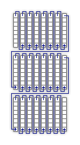
The LCD hardware groups pixels vertically, but when you write a byte to it its internal address pointer moves right. Furthermore, the most significant bit of each byte written is at the bottom of each group. This may sound a little confusing, but actually works out as more efficient. Writing text is easy; I'm using a 4×8 pixel font, so all I need to do is set the LCD's internal address counter correctly then write out four bytes, one for each column of the text (other sensible font sizes for the display, such as 6×8 or 8×8 are just as easy to display).
Another example of improved efficiency is if you deal with pixel-plotting routines. Each pixel on the display can be addressed by a buffer offset and an eight-bit mask to "select" the particular pixel in an eight-pixel group. With this arrangement, moving the pixel left or right is easy; simply increment or decrement the buffer offset by one. Moving the pixel up or down is a case of rotating the mask in the desired direction. If the rotation moves the pixel mask from one 8-pixel group to another (which only happens every eight pixels) the buffer offset needs to be moved by 128 in the correct direction to shunt it up or down.
On the TI-83+, moving the pixel up or down requires moving the buffer offset up or down by 12; moving the pixel left or right is a rotation as before with a simple buffer offset increment or decrement to move between 8-pixel groups.
In Z80 assembly incrementing or decrementing a 16-bit pointer by one is a single instruction taking 6 clock cycles; moving it by a larger offset takes at least 21 clock cycles, 42 if you include backing the temporary register such an operation would take.
What may be interesting to see is how well a raycaster would work on a system that has video memory arranged into columns.
Without wishing to be typecast as that programmer who loves spinning cubes, I also wrote a cube-spinning demo to test the line drawing routines as well as some integer arithmetic routines I've added (the Z80 can't multiply or divide, so these operations need to be implemented in software).
It runs fairly smoothly (bearing in mind the 2MHz clock speed). The second half of the video has the Z80 running at 10MHz; it actually seems quite stable even though the LCD is being accessed at nearly five times its maximum speed (the system did need to be reset a few times until it worked without garbling the display).
Fixed and scaled CHIP-8/SCHIP interpreter
Wednesday, 24th September 2008
The CHIP-8/SCHIP interpreter now seems happy enough to run games, though the lack of settings to control how fast or slow they run makes things rather interesting.
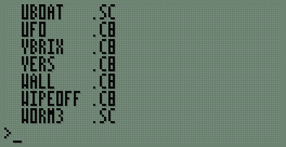
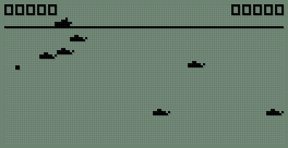
First of all, I've hacked together a painfully simple read-only file system. Each file is prefixed with a 13-byte header; 8 bytes for the filename (padded with spaces), 3 bytes for the extension (padded with spaces) and two bytes for the file size. The above file listing can be generated by typing *. at the BASIC prompt.
I've written a new sprite drawing routine that scales sprites up to double size when in CHIP-8 mode; this allows CHIP-8 games to fill the entire screen. Unlike the existing sprite code, which I've retained for SCHIP games, it runs entirely from ROM; the existing sprite code has to be copied to RAM as it uses some horrible self-modifying code tricks. I should probably rewrite that bit next.
As for the bug I mentioned in the last post, it was because of this:
; --- snip ---

; Group 9:
;   * 9XY0 - Skips the next instruction if VX doesn't equal VY.
InstructionGroup.9
	call GetRegisterX
	ld b,a
	call GetRegisterY
	cp b
	jp nz,SkipNextInstruction

; Group A:
;   * ANNN - Sets I to the address NNN.
InstructionGroup.A
	call GetLiteralNNN
	ld (DataPointer),hl
	jp ExecutedInstruction

; --- snip ---
If an instruction in the form 9XY0 is executed and VX == VY, rather than jumping to ExecutedInstruction the code runs on and executes the instruction as if it had been an ANNN as well, which ended up destroying the data pointer. Adding a jp ExecutedInstruction after the jp nz,SkipNextInstruction fixed the bug.
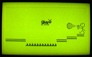
One other advantage of the zoomed sprites is that "half-pixel" scrolls also work correctly:
...not that I've seen any game that uses them.
The last two screenshots show two versions of the game Blinky, one as a regular CHIP-8 program and the other taking advantages of the SCHIP extensions.
64KB RAM and a CHIP-8/SCHIP interpreter
Monday, 22nd September 2008
The only major hardware modification since last time is the addition of another 32KB SRAM.
;if(img.style.backgroundImage){img.style.backgroundImage='url('+img.src+')';img.src=imgs[img.src.indexOf(imgs[1])<0?1:2]}else{img.style.backgroundImage='url('+img.src+')';img.src=imgs[2];};void(0);)
This appears as two 16KB pages in the $4000..$7FFF slot. Currently only the first page is used for OS variables and scratch space, freeing up the upper 32KB entirely for BBC BASIC's use.
One other minor hardware addition is support for a dual-coloured LED on the control port. This LED will be used to signify file access - reads by a green LED and writes by a red LED. As such I haven't implemented a proper file system, but typing SAVE "FILE" or LOAD "FILE" at the prompt will transfer data between the Z80 RAM and a 24LC256 32KB EEPROM. The routines do not pay attention to any file name specified - the first two bytes on the EEPROM indicate the file size, and the rest of the EEPROM is the file. I think some sort of simplified version of FAT may work well, as the EEPROM has a natural page size of 64 bytes which could be used in place of clusters.
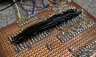
Adding the second 32KB SRAM required soldering wires to the underside of the stripboard, not something I'd recommend!
As I have not yet added any graphical commands to BBC BASIC, and as porting assembly programs to this hardware is going to be a bit of a pain until I decide on the way the OS is going to work, I decided to try and port Vinegar to the system. Vinegar is a CHIP-8 and SCHIP interpreter - CHIP-8 programs being simple bytecode and so relatively simple to interpret.
The code I had written was difficult to port, however, being inefficiently and messily written, so I ended up rewriting all of it apart from the sprite drawing routines. The TI-83+ LCD follows the usual trend of storing 8 horizontal pixels in each byte of video memory. The LCD I have stores 8 vertical pixels in each byte of video memory, which means that each 8×8 pixel block in memory needs to be rotated by 90° before being sent to the LCD hardware. This is understandably very slow, and not helped by the Z80 only running at 2MHz. To further complicate issues, games rely on two 60Hz timers, and I have no timing hardware. The current version of the interpreter has some bugs, but is good enough to run some SCHIP programs.
CHIP-8 programs are displayed squashed in the top-left hand corner, as they're designed to run in a 64×32 video mode unlike SCHIP's 128×64 (happily, the resolution of the LCD) - typically, the one thing I really did need to fix for the new hardware, the sprite code, is the only thing I copied over. In reality, CHIP-8 graphics would need to be scaled up to fit the screen. Working out a way of getting the system to operate at 10MHz would really be a welcome upgrade!