BBC BASIC running as an application
Tuesday, 3rd June 2008
Richard Russell has kindly supplied the project with the BBC BASIC relocatable modules — compiled object files which can be relocated to any memory address by a linker — which means that BBC BASIC can now be configured to run on the TI's hardware.
The tools to relocate the modules run under CP/M, which means that rather trying to integrate the relocation into the build process (which would be a little awkward) I'm going to relocate the modules to a fixed base address and inject the resulting binary file directly into the application.
BBC BASIC will reside from &4100. From &4000..&40FF is a jump table, which BASIC uses to interact with the host. As the addresses of the host interface entry points will change as the code changes, and I don't wish to keep on relinking BASIC in CP/M, a fixed jump table makes life a lot easier. BASIC jumps to a predetermined fixed address in the jump table, which redirects - via a second jump - to the real entry point.


I think I've implemented all of the main host interface entry points, though some — notably those involved in file I/O — need making more robust. I don't currently reserve any memory for BASIC's scratch area, which means that the TI-OS can (and does) decide to overwrite it at inconvenient moments. Even though TI provided us with at least three different 768-byte buffers (the exact size of BBC BASIC's scratch area), none of them are aligned to a 256 byte boundary. 
Z80 BBC BASIC - Emulated on Windows
Thursday, 22nd May 2008
I've started working with the actual BBC BASIC interpreter. As it won't run in its current state on the TI calculator (it relies on a jump table at &FF80..&FFFF to interact with the host, which is protected) I'm using the Z80 emulator I wrote for Cogwheel to try and puzzle out what the host interface should be doing from the relative sanity of C# code (the jump table is populated with OUT (n), A instructions which are subsequently trapped and handled by the emulator).
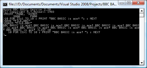
One thing I hadn't realised is that the graphics operations that BBC BASIC offers are actually implemented via the OSWRCH handler (OS WRite CHaracter), which means that BBC BASIC's PLOT, MOVE and DRAW commands will also be available, as well as any commands that use them indirectly (such as CIRCLE).
BBC BASIC
Monday, 19th May 2008
This is a project I initially attempted to get off the ground about four years ago, but never did. Anyhow, I've started work on it, and thanks to help from Richard Russell (the original developer) and J.G.Harston (who comparatively recently developed the Sinclair ZX Spectrum port) it looks like it should be possible this time around. 
BBC BASIC was the native programming language on Acorn's BBC Micro. It's a structured BASIC dialect and supports procedures and functions, permitting far nicer code than the line-numbered GOTO and GOSUB code on other contemporary machines. It also has a built-in assembler, for inline assembly.
There is no source available, which is where the problems start to come in. Fortunately, J.G.Harston has developed a utility that permits the platform-agnostic BBC BASIC interpreter to be relocated. However, it assumes that the system has a jump table in RAM from $FF80..$FFFF (this jump table would be used to call platform-specific code); this memory range is not executable on the TI-83+. Execution protection in the $C000..$FFFF range may also cause issues for inline assembly code (which is, naturally, executed from RAM).
The TI-OS does not offer an especially suitable environment for BBC BASIC either; it is mainly menu driven (a command-line driven environment is preferable), does not have a plain text editor and does not use ASCII. To resolve this issues, I've concentrated on developing a suitable environment for BBC BASIC to live in, including a command-line interface and text editor.

Text files are stored as AppVars with a TEXTFILE header, and I've developed a Windows-based notepad clone for editing them (it saves and loads directly to and from .8xv). The following commands are currently supported (see here for a reference from the Windows verion): BYE, COPY, DELETE, DIR, ERASE, EXEC, QUIT, RENAME, TYPE, |.
To enter the editor, EDIT can be used. This presents a full-screen editor a little like the TI-OS program editor, but edits plain text files.
The interface transparently supports AT keyboards (which are rather easier to type on than the TI's keypad). The character resolution is 24 columns in 10 rows (4x6 pixel characters), giving you quite a lot of room to see what you're working on.
I intend on the final program being a 2-page Flash application; one page for BBC BASIC, and one page for the environment and OS interface. This unfortunately makes this a TI-83+ only project.
Even if I don't manage to shoe-horn BBC BASIC onto the TI-83+, the interface code (which uses direct hardware access for everything but opening and editing AppVars) could be useful for other projects.
CSG, fisheye and spotlights.
Monday, 5th May 2008
One way of constructing solids is to use a method named constructive solid geometry (or CSG for short). I added two simple CSG operators - intersection and subtraction - that both take two surfaces and return the result.

In the above image, the surface that makes up the ceiling is created by subtracting a sphere from a plane. Of course, much more interesting examples can be created. For example, here is the surface created by taking a sphere and subtracting three cylinders from it (each cylinder points directly along an axis).

One problem with the camera implementation was that it couldn't be rotated. To try and aid this, I used a spherical to cartesian conversion to generate the rays - which has the side-effect of images with "fisheye" distortion.


The above left image also demonstrates a small amount of refraction - something that I've not got working properly - through the surface. The above right image is the result of the intersection of three cylinders aligned along the x,y and z axes.
To try and combat the fisheye distortion, I hacked together a simple matrix structure that could be used to rotate the vectors generated by the earlier linear projection. The result looks a little less distorted!


The final addition to the raytracer before calling it a day was a spotlight. The spotlight has an origin, like the existing point light - but it adds a direction (in which it points) and an angle to specify how wide the beam is. In fact, there are two angles - if you're inside the inner one, you're fully lit; if you're outside the outer one, you're completely in the dark; if you're between the two then the light's intensity is blended accordingly.

In the above screenshot, a spotlight is shining down and backwards away from the camera towards a grid of spheres.
If you're interested in an extremely slow, buggy, and generally badly written raytracer, I've uploaded the C# 3 source and project file. The majority of the maths code has been pinched and hacked about from various sites on the internet, and there are no performance optimisations in place. I do not plan on taking this project any further.

Building and running the project will result in the above image, though you may well wish to put the kettle on and make yourself a cup of tea whilst it's working.
Cylinders and translucent surfaces
Tuesday, 29th April 2008


The first addition to the raytracer was a cylindrical surface, represented by two end points and a radius. In the two screenshots above, the cylinder is infinitely long - not very useful. However, by calculating the point on the cylinder's axis that is closest to the struck point on its surface you can work out how far along its axis you are, and from that whether you are between either of the cylinder's ends.


The cylinder can have its ends optionally capped. To add the caps, you can create plane that has a normal that points in the the direction of the cylinder's axis. If you collide with the plane, you can then calculate the distance between the point you struck on it and the end coordinate of the cylinder. If this distance is smaller than the radius of the cylinder, you've hit one of the end caps.


Texturing the cylinders proved rather difficult. The v component of the texture component can be calculated by working how far along the cylinder's axis you are - easy. However, to wrap a texture around the rotational axis of the cylinder is a bit more complicated. In the first screenshot, I simply used Math.Atan2(z,x) to get the angle, and hence texture coordinate - but this only works if the cylinder points along the y axis. If I had another vector that lay perpendicular to the cylinder's axis I could use the dot product to work out its angle, but I don't. The cross product could generate one, but I'd need another vector to cross the axis with... In the end, this post came to my rescue, and I managed to get it working for cylinders pointing along any axis - producing the second screenshot.
An addition I've wanted to make for a while was support for translucent surfaces.

This required a few changes to the structure of the raytracer. Previously, all methods for calculating ray intersections had to return a single Collision object, which contained a boolean flag specifying whether the collision was succesful. A translucent sphere would need to return two collision points - one as the ray enters the front and one as it leaves the back of its surface. To this end, all collision detection methods now return an array (empty or null if no collisions were made), and each collision has a flag indicating whether the collision was made by the ray entering the solid or leaving the solid (this is required, for example, to invert surface normals for correct shading).
Once the nearest struck point to the camera has been handled (including recursive reflection-handling code) it is checked to see if it's on a translucent surface. If so, the raytracer continues raytracing away from the camera, and blends the new result with the existing result based on its opacity. By stopping and starting again, one can adjust the direction of the ray - for example, to add a refraction effect (which I have not yet got working ).
One trick the above image misses is that it's still simply scaling down the intensity of the light by the opacity of the surface it passes through. It would look nicer if the light was coloured by the surface it passes through; so, in the above example, the white light shining through the blue water on the sphere should cast blue-tinted shadows.

Whilst it's far from being real-time, I can still make it dump out a sequence of frames to create a basic animation.