Bounding Box Bouncing
Friday, 14th September 2007
I've updated the collision detection between points and the world with Scet's idea of only testing with the faces in the leaf containing the start position of the point.

ZiggyWare's Simple Vector Rendering GameComponent is being very useful for testing the collision routines. 
I have also extended the collision routines to bounding boxes. This fixes a few issues where a point could drop through a crack in the floor between two faces.
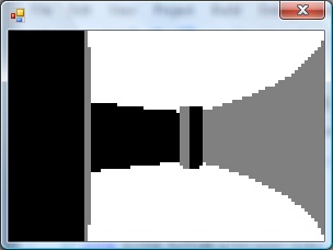
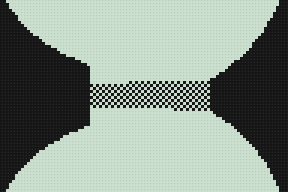
My technique is to test the collision between the eight corners of the box and then to pick the shortest collision and use that as the resultant position. This results in a bounding box that is not solid; you can impale it on a spike, for example.
In the above screenshot, the cube comes to rest with the corners all lined up on cracks, which means that it slips through as its base isn't solid.

Happily, object collisions are simple bounding-box affairs, the bounding boxes set with QuakeC code, which should simplify things somewhat.
Goodness Gracious, Great Balls of Lava
Wednesday, 12th September 2007
I've reworked the VM completely to use an array of a union of a float and an int, rather than the MemoryStream kludge I was using before. This also removes a lot of the multiply-or-divide-by-four mess I had with converting indices to positions within the memory stream.
There are (as far as I know) three ways to invoke QuakeC methods. The first is when an entity is spawned, and this is only valid when the level is being loaded (the function that matches the entity's classname is called). The second is when an entity is touched (its touch function is called) and the third is when its internal timer, nextthink, fires (its think function is called).
The third is the easiest one to start with. On a monster-free level, there are still "thinking" items - every powerup item has droptofloor() scheduled to run.
A strange feature of custom levels has been that all of the power-up items have been floating in mid-air.

By hacking together some crude collision detection (face bouncing boxes and axial planes only) I could make those objects sit in the right place:

With many thanks to Zipster pointing me in the right direction I have extended this to perform collision detection of a moving vertex against all world faces.
Here I fire a vertex (with a lava ball drawn around it to show where it is) through the world. When I hit a face I reflect the velocity by the face normal.
It looks much more realistic if I decrease the velocity z component over time (to simulate gravity) and reduce the magnitude of the velocity each time it hits a surface, so I can now bounce objects around the world:
Performing the collision detection against every single face in the world is not very efficient (though on modern hardware I'm still in the high nineties). There are other problems to look into - such as collisions with invisible brushes used for triggers and collision rules when it comes to water and the sky, not to mention that I should really be performing bounding-box collision detection, not just single moving points. Points also need to slide off surfices, not just stop dead in their tracks.
Once a vertex hits a plane and has been reflected I push it out of the surface very slightly to stop it from getting trapped inside the plane. This has the side effect of lifting the vertex a little above the floor, which it then drops back against, making it slide down sloping floors.
Entities Spawned by QuakeC Code
Thursday, 6th September 2007
After all that time spent trying to work out how the QuakeC VM works I finally have some real-world results.
Apart from the obvious boring stuff going on in the background parsing and loading entities go, two functions in particular are of note. The first is a native function, precache_model(string) which loads and caches a model of some description (sprites, Alias models or BSP models). The QuakeC VM I've written raises an event (passing an event containing the name of the model to load), which the XNA project can interpret and use to load a model into a format it's happy with.

Inspiration for the Strogg in Quake 2?
With a suitable event handler and quick-and-dirty model renderer in place, the above models are precached (though they probably shouldn't be drawn at {0, 0, 0}).
The second function of interest is another native one, makestatic(entity). Quake supports three basic types of entity - dynamic entities (referenced by an index, move around and can be interacted with - ammo boxes, monsters and so on), temporary entities (removes itself from the game world automatically - point sprites) and static entities. Static entities are the easiest to handle - once spawned they stay fixed in one position, and can't be accessed (and hence can't be removed). Level decorations such as flaming torches are static. Here's the QuakeC code used to spawn a static small yellow flame:
void() light_flame_small_yellow =
{
	precache_model ("progs/flame2.mdl");
	setmodel (self, "progs/flame2.mdl");
	FireAmbient ();
	makestatic (self);
};
// Handle precache models:
void Progs_PrecacheModelRequested(object sender, Quake.Files.QuakeC.PrecacheFileRequestedEventArgs e) {
	switch (Path.GetExtension(e.Filename)) {
		case ".mdl":
			if (CachedModels.ContainsKey(e.Filename)) return; // Already cached.
			CachedModels.Add(e.Filename, new Renderer.ModelRenderer(this.Resources.LoadObject<Quake.Files.Model>(e.Filename)));
			break;
		case ".bsp":
			if (CachedLevels.ContainsKey(e.Filename)) return; // Already cached.
			CachedLevels.Add(e.Filename, new Renderer.BspRenderer(this.Resources.LoadObject<Quake.Files.Level>(e.Filename)));
			break;
	}
}

// Spawn static entities:
void Progs_SpawnStaticEntity(object sender, Quake.Files.QuakeC.SpawnStaticEntityEventArgs e) {
	// Grab the model name from the entity.
	string Model = e.Entity.Properties["model"].String;

	// Get the requisite renderer:
	Renderer.ModelRenderer Renderer;
	if (!CachedModels.TryGetValue(Model, out Renderer)) throw new InvalidOperationException("Model " + Model + " not cached.");

	// Add the entity's position to the renderer:
	Renderer.EntityPositions.Add(new Renderer.EntityPosition(e.Entity.Properties["origin"].Vector, e.Entity.Properties["angles"].Vector));
}
The result is a light sprinkling of static entities throughout the level.

As a temporary hack I just iterate over the entities, checking if each one is still active, and if so lumping them with the static entities.

If you look back a few weeks you'd notice that I already had a lot of this done. In the past, however, I was simply using a hard-coded entity name to model table and dumping entities any old how through the level. By parsing and executing progs.dat I don't have to hard-code anything, can animate models correctly, and even have the possibility of running the original game logic.
An example of how useful this is relates to level keys. In some levels you need one or two keys to get to the exit. Rather than use the same keys for each level, or use many different entity classes for keys, the worldspawn entity is assigned a type (Mediaeval, Metal or Base) and the matching key model is set automatically by the key spawning QuakeC function:
/*QUAKED item_key2 (0 .5 .8) (-16 -16 -24) (16 16 32)
GOLD key
In order for keys to work
you MUST set your maps
worldtype to one of the
following:
0: medieval
1: metal
2: base
*/

void() item_key2 =
{
	if (world.worldtype == 0)
	{
		precache_model ("progs/w_g_key.mdl");
		setmodel (self, "progs/w_g_key.mdl");
		self.netname = "gold key";
	}
	if (world.worldtype == 1)
	{
		precache_model ("progs/m_g_key.mdl");
		setmodel (self, "progs/m_g_key.mdl");
		self.netname = "gold runekey";
	}
	if (world.worldtype == 2)
	{
		precache_model2 ("progs/b_g_key.mdl");
		setmodel (self, "progs/b_g_key.mdl");
		self.netname = "gold keycard";
	}
	key_setsounds();
	self.touch = key_touch;
	self.items = IT_KEY2;
	setsize (self, '-16 -16 -24', '16 16 32');
	StartItem ();
};

Mediaeval Key

Metal Runekey

Base Keycard
One problem is entities that appear at different skill levels. Generally higher skill levels have more monsters, but there are other level design concerns such as swapping a strong enemy for a weaker one in the easy skill mode. In deathmatch mode entities are also changed - keys are swapped for weapons, for example. At least monsters are kind - their spawn function checks the deathmatch global and they remove themselves automatically, so adding the (C#) line Progs.Globals["deathmatch"].Value.Boolean = true; flushes them out nicely.
Each entity, however, has a simple field attached - spawnflags - that can have bits set to inhibit the entity from spawning at the three different skill levels.

Easy

Medium

Hard
Regrettably, whilst the Quake 1 QuakeC interpreter source code is peppered with references to Quake 2 it would appear that Quake 2 used native code rather than QuakeC to provide gameplay logic, so I've dropped development on the Quake 2 side at the moment.
QuakeC
Monday, 3rd September 2007
This journal hasn't been updated for a while, I know. That doesn't mean that work on the Quake project has dried up - on the contrary, a fair amount of head-way has been made!

The problem is that screenshots like the above are really not very interesting at all. 
As far as I can tell, Quake's entity data (at runtime) is stored in a different chunk of memory to the memory used for global variables. I've had numerous problems getting the code to work - most of which caused by pointer confusion. Four bytes are generally used for a field (vectors use three singles, so you have 12 bytes), so I've tried multiplying and dividing offsets by four to try and get it all to work.
The basic entity data is stored in the .bsp file. It takes the following form:
{
"worldtype" "2"
"sounds" "6"
"classname" "worldspawn"
"wad" "gfx/base.wad"
"message" "the Slipgate Complex"
}
{
"classname" "info_player_start"
"origin" "480 -352 88"
"angle" "90"
}
{
"classname" "light"
"origin" "480 96 168"
"light" "250"
}
classname describes the type of the entity, and the other key-value pairs are used to adjust the entity's properties. All entities share the same set of fields, which are declared in a special section of the progs.dat file.
For each classname there is a matching QuakeC function. As far as I can tell the trick is to decode an entity then invoke its QuakeC method.
void() light =
{
	if (!self.targetname)
	{	// inert light
		remove(self);
		return;
	}

	if (self.style >= 32)
	{
		self.use = light_use;
		if (self.spawnflags & START_OFF)
			lightstyle(self.style, "a");
		else
			lightstyle(self.style, "m");
	}
};
As you can probably guess, if a light entity is not attached to a particular target it is automatically removed from the world as it serves no useful function (the lightmaps are prerendered, after all). A similar example comes from the monsters which remove themselves if deathmatch is set. The QuakeC code also contains instructions on setting which model file to use for each entity and declares the animation frame sequences, so is pretty important to get working.
I have a variety of directories stuffed with images on my website, and (thankfully) I have used a faintly sane naming convention for some of these. I knocked together a PHP script which reads the files from these directories and creates a nifty sort of gallery. It automatically generates thumbnails and is quite fast. As I don't have an internet connection at home it's more practical to be able to just drop files into a directory and have the thing automatically update rather than spend time updating a database.
PHP source code (requires GD).
It's INI file driven. The two files are config.ini:
[Site]
base_dir=../../ ; Base directory of the site
; I put this in bin/gallery, so need to go up two levels :)

[Files]
valid_extensions=jpg,gif,png ; Only three that are supported

[Thumbnails]
max_width=320
max_height=256
quality=90 ; Thumbnail JPEG quality
...and galleries.ini:
[VB6 Terrain]
key=te                 ; Used in gallery=xyz parameter
path=projects/te       ; Image location, relative to base_dir
date_format=ddmmyyyyi  ; Filename format, where i = index.

[MDX DOOM]
key=doom
path=images/doom
ignore_extensions=jpg     ; Can be used to ignore extensions.
date_format=yyyy.mm.dd.ii
The index in the date format is for files that fall on the same date. Historically I used a single letter (01012003a, 01012003b), currently I use a two-digit integer (2003.01.01.01).
If a text file with the name of the image + ".txt" is found, that is used as a caption. (eg, /images/quake/2003.01.01.01.png and /images/quake/2003.01.01.01.png.txt).
It's not designed to be bullet-proof (and was written very very quickly) but someone might find it a useful base to work on.
8-bit Raycasting Quake Skies and Animated Textures
Monday, 20th August 2007
All of this Quake and XNA 3D stuff has given me a few ideas for calculator (TI-83) 3D.
One of my problems with calculator 3D apps is that I have never managed to even get a raycaster working. Raycasters aren't exactly very tricky things to write.
So, to help me, I wrote a raycaster in C#, limiting myself to the constraints of the calculator engine - 96×64 display, 256 whole angles in a full revolution, 16×16 map, that sort of thing. This was easy as I had floating-point maths to fall back on.
With that done, I went and ripped out all of the floating-point code and replaced it with fixed-point integer arithmetic; I'm using 16-bit values, 8 bits for the whole part and 8 bits for the fractional part.
From here, I just rewrote all of my C# code in Z80 assembly, chucking in debugging code all the way through so that I could watch the state of values and compare them with the results from my C# code.

The result is rather slow, but on the plus side the code is clean and simple. The screen is cropped for three reasons: it's faster to only render 64 columns (naturally), you get some space to put a HUD and - most importantly - it limits the FOV to 90°, as the classic fisheye distortion becomes a more obvious problem above this.
I sneaked a look at the source code of Gemini, an advanced raycaster featuring textured walls, objects and doors. It is much, much faster than my engine, even though it does a lot more!
It appears that the basic raycasting algorithm is pretty much identical to the one I use, but gets away with 8-bit fixed point values. 8-bit operations can be done significantly faster than 16-bit ones on the Z80, especially multiplications and divisions (which need to be implemented in software). You can also keep track of more variables in registers, and restricting the number of memory reads and writes can shave off some precious cycles.
Some ideas that I've had for the raycaster, that I'd like to try and implement:
- Variable height floors and ceilings. Each block in the world is given a floor and ceiling height. When the ray intersects the boundary, the camera height is subtracted from these values, they are divided by the length of the ray (for projection) and the visible section of the wall is drawn. Two counters would keep track of the upper and lower values currently drawn to to keep track of the last block's extent (for occlusion) and floor/ceiling colours could be filled between blocks.
- No texturing: wall faces and floors/ceilings would be assigned dithered shades of grey. I think this, combined with lighting effects (flickering, shading), would look better than monochrome texture mapping - and would be faster!
- Ray-transforming blocks. For example, you could have two 16×16 maps with a tunnel: the tunnel would contain a special block that would, when hit, tell the raycaster to start scanning through a different level. This could be used to stitch together large worlds from small maps (16×16 is a good value as it lets you reduce level pointers to 8-bit values).
- Adjusting floors and ceilings for lifts or crushing ceilings.
As far as the Quake project, I've made a little progress. I've added skybox support for Quake 2:

Quake 2's skyboxes are simply made up of six textures (top, bottom, front, back, left, right). Quake doesn't use a skybox. Firstly, you have two parts of the texture - one half is the sky background, and the other half is a cloud overlay (both layers scroll at different speeds). Secondly, it is warped in a rather interesting fashion - rather like a squashed sphere, reflected in the horizon:
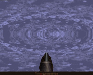
For the moment, I'm just using the Quake 2 box plus a simple pixel shader to mix the two halves of the sky texture.

I daresay something could be worked out to simulate the warping.
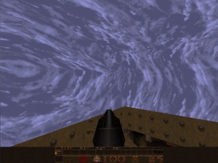
The above is from GLQuake, which doesn't really look very convincing at all.
I've reimplemented the texture animation system in the new BSP renderer, including support for Quake 2's animation system (which is much simpler than Quake 1's - rather than have magic texture names, all textures contain the name of the next frame in their animation cycle).