Internal PS/2 Port
Friday, 6th October 2006
What's that in the bottom left hand corner?

Kerm Martian has added a PS/2 port to his calculator (click the picture for better pictures and the original thread). He has been developing a shell, entitled DoorsCS (click for website) which sports an impressive set of GUI controls - hence the mouse!
Emerson Beta 2
Friday, 22nd September 2006
Sorry about the lack of updates, but I have been incredibly busy with work related programming.
One small project I've had a chance to update is Emerson - my keyboard and mouse library for the TI-83 series calculator.
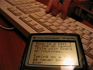

I know, I can't type layout.  Download the library (and demo) here.
Stuff and nonsense
Tuesday, 22nd August 2006
Brass
Important: all versions ≤ 1.0.4.5 have a major bug with ZIDX instructions (eg rr (ix+1)) meaning that they are not output correctly. Please upgrade to 1.0.4.6 as soon as possible.
Other stuff
I haven't had much of a chance to do anything especially exciting of late. I found my PICAXE chips and also found out the reason that one of them never seemed to work was that I was using an old version of the programming software and the chip was an 18X, not a regular 18 (so lots of extra space - can only be a good thing). I'm not sure what to do with them, though. I had thought of using one of the PICAXE-08Ms as a super-cheap "greylink" replacement (cable for TI calculators that deals with the TI byte transfer protocol at one end and RS232 serial at the other - unlike the blacklink that implements the TI byte transfer protocol in software), but I can't read serial data in and output it fast enough and just end up dropping bytes.
Ideas on the back of a postcard, please.
I've been trying to help someone get started with FMOD Ex - they're using VB.NET, and FMOD Ex is only supplied with a C♯ wrapper. No matter, it gave me an opportunity to experiment with class libraries. It was a bit of an anticlimax... just create a new 'class library' project, add the C♯ wrapper files, hit build then add the output DLL as a reference to the VB.NET project. Couldn't be easier.  Just use the System.Runtime.Interop.Marshal class to dump data around rather than the unsafe pointers from the examples and it works like a champ.
Multithreading on the TI-83 Plus
Thursday, 3rd August 2006
I'm not really clued up on the way these new-fangled modern operating systems handle running multiple threads, so I apologise in advance if this isn't really proper multithreading.
Basically, I was pondering (as one does) whether it would be possible to run any number of threads on the TI-83 Plus. I daresay others have done this in the past, but not having access to the internet at the time to check I thought I'd do my own bit of experimentation.
The way I can see this working is to give each thread a small amount of time to run in (time slice). At the end of one thread running, I would save the calculator's state away, and load the state for the next thread. I would keep on swapping threads several times a second, giving each their own bit of time and preserving their state.
What I really needed to know was what needed to be preserved between executions. Really, there isn't a lot - just the registers. PC and SP clearly need to be preserved, so that when a thread is resumed it resumes running at the point it was left at. Keeping the other general-purpose registers (AF, BC, DE, HL, IX, IY) safe would be important as well.
Naturally, I'll need to also preserve the stack. Or rather, for each thread, I'll need to allocate some memory for a stack and point the new thread's SP register at the end of that new memory. To keep things simple, I'll just point my test thread's SP at $FFFF-200, as the TI is arranged to have 400 bytes of stack RAM, growing backwards from $FFFF.
To perform the swapping, I'll use a custom interrupt (run in IM 2). The timer hardware will trigger this interrupt many times a second, so it is ideal. At the end of my custom interrupt, I'll jump into the default handler provided by the TIOS so the TIOS functions that rely on it behave correctly.
The way I see it working is like this:
Pop value off stack. This will be the program counter of the last running thread. (->A)
Save current stack pointer. (->B)
Set stack pointer to area in RAM where I can preserve registers for this thread. (<-C)
Push IY, IX, HL, DE, BC, AF to the stack.
Push old stack pointer (<-B) to stack.
Push old program counter (<-A) to stack.
Find the address of the RAM where we have stored the registers for the next thread.
Load it into the stack pointer.
Pop value off stack, store it (will be PC) (->D)
Pop value off stack, store it (will be SP) (->E)
Pop AF, BC, DE, HL, IX, IY off stack.
Save current stack pointer (end of RAM area used to store registers for new thread) as address of last thread for next interrupt. (->C).
Load value into SP (<-E)
Push new thead's PC to stack (<-D)
Jump into TIOS interrupt handler ->
Effectively, all this does is take the pointer stored when the current thread was resumed, dump all the registers into the memory it points to, hunts the next thread, reloads the registers and saves the pointer for next interrupt.
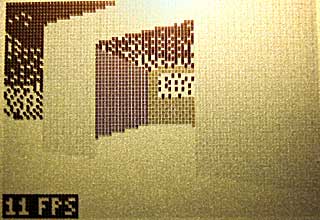
Does it work?

The above screenshot doesn't look too impressive, I'll give you that. There are only two threads running. The secondary thread is drawing all those random dots on the LCD. The other thread (which is the main program thread) just contains "bcall(_getkey)" - hence the 2nd/Alpha icons appearing,
I'll make the primary thread do something a bit more exotic - display random characters on the left side of the screen, the secondary work on the right side of the screen:

The code for this is simply:
Main
	.include "Multithread/Multithread.asm"


	; Kick things into action.
	call Multithread.Init

	; For the moment, the secondary thread is hard-coded, and
	; the 'multithreading' code ONLY switches back and forth between
	; two hard-coded thread slots.
-

	halt ; Slow things down a bit here.

	ld b,8
	call ionRandom
	ld (curCol),a

	ld b,8
	call ionRandom
	ld (curRow),a

	ld b,0
	call ionRandom
	bcall(_PutMap)
	bcall(_getCSC)
	cp skClear
	jr nz,{-}

	call Multithread.End
	ret

; ---------------------------------------------------------

SecondaryThread

	di ; Don't want any other thread writing to the LCD!

	ld b,64
	call ionRandom
	add a,$80
	push af ; Save for later...
		out ($10),a

		ld b,48
		call ionRandom
		add a,48
		ld b,a
		srl a
		srl a
		srl a
		add a,$20
		out ($10),a

		ld a,b
		and 7
		ld c,%10000000
		jr z,{+}
		ld b,a
	-	srl c
		djnz {-}
	+

		in a,($11)
		call LcdBusy
		in a,($11)
		xor c
		ld c,a

		call LcdBusy

	pop af
	out ($10),a

	call LcdBusy
	ld a,c
	out ($11),a

	ei

	jr SecondaryThread

LcdBusy
	push af
	inc hl
	dec hl
	pop af
	ret
As you can see, there are two discrete threads running there.
Well, that's two threads up and running. What's needed to extend this to any number of threads?
- Thread management. Basically, the ability to add/remove threads at will, and have the handler be able to switch between as many threads as required.
- Allocation of new stack space. New threads will need more stack space, so I shall need to add some mechanism to steadily allocate it.
- Idle threads. One big problem is that as you add threads, each one gets progressively slower. If threads flag themselves as idle, they can be skipped so threads that do need CPU time get it. The easiest way to do this is to set a "sleep" counter which is checked when threads are switched around - if it's zero (when it runs out), the thread is given some time to run.
Off the top of my head, that's about it. There are some issues I have come across when working with this:
- TIOS routines are not thread-safe. This speaks for itself, pretty much - if you have two threads, both of which are calling bcall(_putC) to display a character, they interfere with eachother (for example - incorrectly setting the value of curCol or curRow as one thread changes it as the other one is reading it) which causes crashes.
- Variables can become an issue. Same reason as above - if two threads call a function which uses a set RAM location for a local variable, the variable can be changed half way through.
One possible way to get around thread-unsafety of functions is to disable interrupts before calling them and reenabling them afterwards, which prevents the thread switcher from swapping them. It's a pretty lousy workaround, though. 
Map Editing
Wednesday, 26th July 2006
I added five-level grey:
The greyscale effect is optional (adds about 8 lines of code, only runs once per frame and can be disabled with a single switch in the engine package's Settings.inc file.
Anyway, I've started throwing together a very primitive level editor. (GDI+)
Insert inserts a new vertex at the mouse location; delete removes the closest vertex. Point at a vertex, hold W, move to another vertex and release W to insert a new wall. (Single-sided, hold shift at the same time to add a double-sided wall). Use D to remove walls in the same way. That sort of thing.
The two different types of wall are represented with white lines (single-sided) and grey lines (double-sided). There are therefore 9 different sectors in the above image.
Imagine that the walls have been kept simple (fixed floor/ceiling heights, single segment) and can have one of 6 different 'colours' - from 0 (invisible/transparent) to 1 (white) through to 3 (50% grey) and finally 5 (black).
Therefore, for the sake of simplicity, assume that all of the double-sided grey walls in the above screenshot are invisible. The room in the south-west of the screenshot is an octogonal room with a doorway in the eastern wall and a square pillar in the middle.
The four double-sided walls in this south-western room are not redundant. You will notice that the level has been cut up into convex sectors. This has one small advantage - it reduces the number of walls that will need to be sorted, as I only need to sort entire sectors for occlusion purposes.
Also, I can see that I can get some sort of portal*-based system up and running. Suppose I use the editor to create this:
If I was to start in the left sector, I would go through and draw each wall. I'd hit the double-sided wall at some point, and know that after this sector I'd have to move into the sector in the middle. After that sector, I'd know that I'd have to move to the sector to the right. With me so far?
Let's do something radical and make that central sector a door, and close it (move the ceiling height down to meet the floor height). This time, when I move through the sectors, I'll hit this sector and see that it's closed. No matter, say I - rather than carry on walking through the sectors, I stop at that point.
By liberally sprinkling a world with doors, and keeping them shut most of the time, you can cut out a fair chunk of geometry. :)
I cannot think of the best way to handle sorting. I don't think I can just use the order in which I wander through the sectors - imagine this:
Imagine you're in the north 'triangle' and looking south. As you can see, you need to travel through more sectors to get to the larger rectangular room than the south triangular room - and using that for sorting is just wrong.
One potential workaround I can think of is that each sector has a visibility list - a list of in which order sectors appear (in front->back order - else we wouldn't be able to take advantage of portals). Problems; MASSIVE amount of data that grows exponentially with each added sector! From what I can also tell, that also seems a precomputed BSP list, done per sector (rather than work out which side of the split to follow each branch, it's already calculated for us). On the other side, this can also be used to calculate (through some nifty ray/plane intersection algorithm) which sectors will NEVER be visible from a particular sector... Hmm. I'm not afraid of 'wasting' RAM with gigantic tables - if we assume a smallish, plain level of 50 sectors, each sector would need a list of at most 49 other sectors. 49*50*2=4900B - not actually too bad. :
(Bah) Just realised that would not work (precomputed sorting based on sectors) at all.
Let's say the red line is your 'view' (not a wall, quick and dirty diagram). It intersects the front of two walls, so it appears that the sort should go north->east->west sectors. However, imagine I move to the other side of the sector and look the same way (mirror the diagram, basically). Now the order goes north->west->east, and I'm still in the same sector :( Do I just clump all the sectors together and sort them all together based on the distance to the central (average) coordinate of each and the camera? (Not fast!)
Thoughts?
*I hope that's the correct word.